
Abstract
To research the static load sharing performance of non-orthogonal offset helical (NOH) face gear dual-branch drivetrain, the non-orthogonal offset layout forms of the system are explored, and the meshing phase differences of split-stage and converge-stage are analyzed. Based on the torque balance condition, deformation coordination condition, and static balance condition of the system, a static torque distribution model of the system was generated, and the static load sharing coefficients (SLSCs) were obtained results. The influence of assembly errors, support stiffness, torsional stiffness, meshing stiffness, and input load on the static load sharing performance was analyzed. The results indicate that assembly errors have a strong influence on the SLSCs, with the shaft angle errors exerting the strongest influence on the SLSCs; When there are assembly errors, the impact of input load and torsional stiffness on the static load sharing performance is greater than without assembly error. To increase the load sharing performance of the system, the meshing phase differences should be eliminated, and the offset layout form should be adopted in the dual-branch transmission system. In addition, reducing the support stiffness of the input helical gear and the fluctuation amplitude of meshing stiffness can also improve the load sharing performance.
Keywords
Introduction
Helical face gear drives 1 are an advanced new type of angular gear transmission. It is composed of a helical gear and a face gear 2 that can mesh with each other. Face gear drives have unique advantages, such as their large tooth surface overlap, strong load-bearing capacity, high single-stage transmission ratio, and compact structure.3–5 Therefore, it is more suitable for branch drivetrains, especially for aviation drivetrains that are lightweight and work in a narrow space. 6 Helical face gear has larger tooth surface overlap, stronger load-bearing capacity, and more stable transmission performance when compared to spur face gear. 7 In addition, the structure of offset non-orthogonal layout forms is more compact, and the branch drives of face gear pairs have excellent load sharing performance in helicopters. 8 Therefore, research on the application of NOH face gear branch drivetrains in helicopters has attracted much attention.
Since Litvin first proposed a spur face gear branch drivetrain, and the finite element model was created. Litvin et al. 9 also calculated the torque distribution using the finite element method, many scholars or institutions have proposed a series of different types of face gear branch drivetrains and conducted in-depth research on their load sharing characteristic. Pias and Turro 10 designed a face gear branch drivetrain with multiple input shaft, which has an independent load sharing mechanism. The torque is first input by a pinion and divided into two face gears installed concentrically and facing each other. Then, the output shaft, which is connected with the bottom face gear, receives the converged torque through the idler gears. Gmirya and Kish 11 designed a branch drive of face gear pairs similar to the one designed by Pias, and it can achieve multi-path torque branch transmission. The torque is first split through the cylindrical gear pairs, then transmitted to the face gear pairs composed of four concentric installed face gears and two pinions, achieving secondary split, and finally converged through the idler gears. Afterwards, Gmirya 12 has also designed a branch transmission device that provides multi-path and three-stage power gear transmission. In this system, torque is delivered from the high-speed input shaft to the first stage face gear pairs, then divided by the second stage spur gear pairs, and finally converged by the third stage herringbone gear pairs to the low-speed output shaft, and achieves even load through the floating pinion.
In recent years, Kawasaki et al. 13 proposed a method for designing helical pinions by defining a reference point between helical pinions and face gears. The influence of helix angle on surface contact was analyzed, providing a design method for the application of helical face gear transmission instead of bevel gear and hypoid gear transmission. Zschippang et al. 14 proposed a method for calculating load sharing, transmission performance, and contact pressure of face gear transmission. This method combines the analysis of the contact path for rigid gear meshing with finite element analysis of load related compliance, greatly improving computational efficiency. In recent years, Zhao et al. 15 have studied the branch drivetrain of concentric face gears, established its static load sharing calculation equations, and revealed the reasons for the uneven load of the system. Dong et al.16–18 researched the branch drivetrain of concentric face gears and the four-branch drivetrain of face gears, and analyzed the effects of differences, stiffness, and other factors on the static load sharing performance of two systems. He also conducted research on the twin rotors concentric face gear power-split drivetrain 19 and proposed optimization design methods for its load sharing and lightweight design. Gong et al. 20 considered the elastic support conditions of the concentric face gear branch drivetrain and established its quasi-static analysis model to study its uniform load performance and contact characteristics. Mo et al. 21 proposed a double input face gear split-parallel transmission system and explored its dynamic vibration characteristics. In summary, the structural types of face gear branch drivetrains are diverse and varied. A series of related research achievements have greatly promoted the innovate of face gear branch transmission in the aviation field, especially in the field of helicopter power transmission. However, the aforementioned research mostly focusses on spur face gears, and research on helical face gears is very rare, with less consideration given to non-orthogonal and offset situations. The dual-branch transmission of face gears is the basic configuration of face gear branch transmission. Therefore, studying the load sharing performance of NOH face gear dual-branch drivetrain can provide theoretical reference for its application in other types of face gear branch drivetrains.
The load sharing performance of NOH face gear dual-branch drivetrain is studied in this article. Firstly, the dual-branch layout forms of NOH face gears, and meshing phase differences are analyzed. Secondly, considering factors, such as assembly errors, loads, support stiffness, torsional stiffness, and meshing phase stiffness, this study establishes a static torque distribution equations of NOH face gear dual-branch drivetrain. Finally, the influences of these factors on the static load sharing performance of this drivetrain are analyzed.
The structure of the drivetrain and the non-orthogonal offset layout form
The structure of the drivetrain
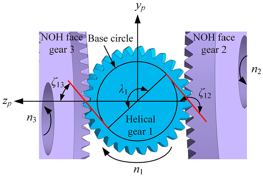
The NOH face gear dual-branch drivetrain mainly includes the NOH face gear pairs in the split-stage and the helical gear pairs in the converge-stage. And its structural diagram is shown as Figure 1. The torque enters the system through the input shaft, and is divided into two branches by the helical gear 1 to transfer to the NOH face gears 2 and 3. The elastic shaft 24 connects the NOH face gear 2 and the helical gear 4, the elastic shaft 35 connects the NOH face gear 3 and the helical gear 5, and the helical gear 4 and 5 converge and transfer the torque to the helical gear 6, which connects the output shaft.

The structural diagram of NOH face gear dual-branch drivetrain.
The non-orthogonal offset layout form
The layout form of NOH face gear pairs is shown in Figure 1, which means that the offset direction is opposite and the offset angle is equal, and the shaft angle is equal and acute. Among them, the definition of the offset angle

Where
Due to the identical tooth surfaces of NOH face gears 2 and 3, the offset angles between NOH face gear pairs 12 and 13 are equal. The tooth surfaces geometry of the helical gear is asymmetric. So, the opposite offset direction are necessary to ensure that the meshing tooth surfaces of two NOH face gears are the same and have the same meshing characteristics, which is conducive to achieving equal load distribution between two branches. When the shaft angle is greater than 90°, the space of the input helical gear axis is easily limited. However, when the shaft angle is less than 90°, there is a large variation space in the input helical gear axis, which is conducive to adjusting input shaft direction flexibly. By adopting a non-orthogonal and offset layout form, not only can both NOH face gears have double span support conditions, improving support stiffness and system stability, but also can form almost any input and output angle and any configuration of a branch drivetrain. This can provide rich configuration options for aviation drivetrains that are compact and work in a narrow space, especially for the drivetrains in helicopters.
The force on NOH face gear
The NOH face gears have more complex forces than that of non-orthogonal and offset spur face gears, as shown in Figure 2. The angle

The force on NOH face gear.
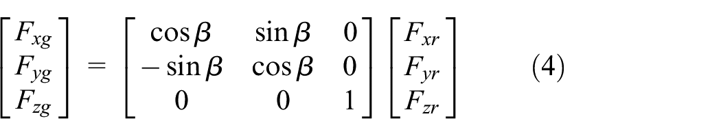
In the coordinate system
Firstly, decompose it into force

Secondly, decomposing

Finally, these forces are transformed into the coordinate system
Static model and equations
Static model
Simplify the static modeling of the system as follows: the support of the gear and the teeth are treated as springs, and the wheel itself is treated as a rigid body; Not considering phenomena such as gear disengagement, reverse impact, torsion, and vibration between gears; Neglecting frictional force, inertial force, gravity, and thermal expansion force. The static model of NOH face gear dual-branch drivetrain is shown as Figure 3.

Static model of NOH face gear dual-branch drivetrain.
In the coordinate system
Meshing phase differences
It is necessary to determine the meshing phase differences of each gear pair. The arc length between the meshing lines of two face gear pairs is measured on the helical gear 1. This arc length corresponds to a center angle which is defined as the meshing phase difference in the Kahraman, 22 as shown in Figure 4.
The angular position relationship between two NOH face gear pairs under elastic support.
Let the meshing phase differences of helical gear 1 be
When the meshing point between helical gear 1 and NOH face gear 2 is determined, the relative meshing point between helical gear 1 and NOH face gear 3 depends on the magnitude of the meshing phase differences

Where
Let the meshing phase differences of helical gear 6 be

The angular position relationship between two helical gear pairs under elastic support.
Similarly, the relationship between the meshing phase differences and the meshing cycles can be expressed as
Where
Assembly errors and elastic deformation transform along the meshing line direction
The relationship between the angle and position of two NOH face gear pairs under elastic support is shown in Figure 3.

Where
Let

Where
The angle position relationship between two pairs of helical gear pairs under elastic support is shown in Figure 4.
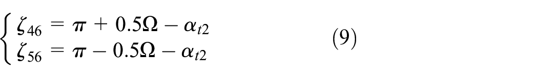
Where
Let

Where
Torque distribution under elastic support
The torque transmission relationship of the system and the torque angle relationship of each gear pair are shown in Figure 6.

System torque transmission relationship and torsion angle relationship.
The input torque of helical gear 1 is
According to the torque transmission relationship of the system, the torque balance condition can be obtained as

Where
According to the system torsion angle relationship, the torsion angle deformation coordination condition is shown as follows:

Where
The static balance condition of the system under elastic support is shown as:
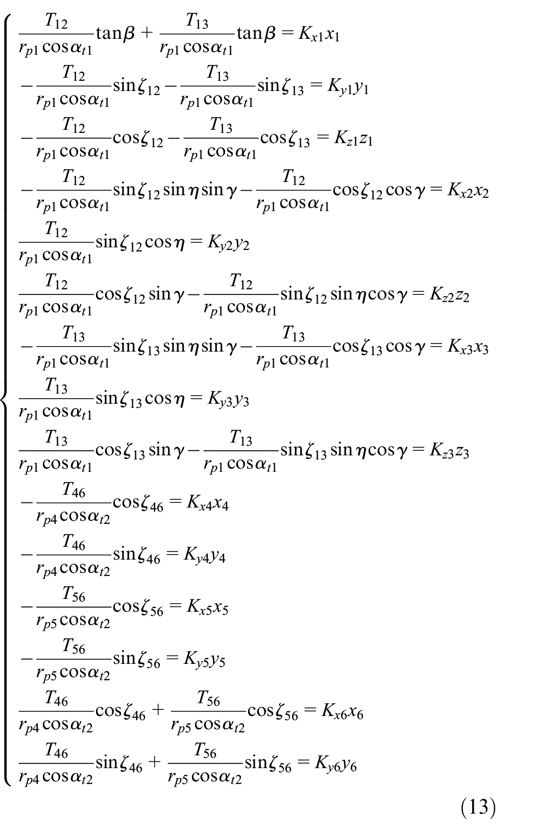
The torque balance condition, torsion angle deformation coordination condition, and static balance condition of the joint system are used to obtain the mathematical model of torque distribution of the system under elastic support.
Calculation method of the SLSC
At present, there is no unified standard definition for the average load coefficient of multi-stage gear branch drivetrains, and some research papers on face gear branch transmission23,24 also have different definitions of the average load coefficient. According to Fu et al., 25 the average load coefficient of a branch drivetrain is defined as the ratio of the actual distributed torque of each gear pair to the theoretical distributed torque of that branch.
Based on the torque distribution mathematical model of the system under elastic support, the torque distribution of each gear pair can be solved. The SLSCs

Within one meshing cycle, the maximum SLSC between two NOH face gear pairs is defined as the SLSC in the split-stage. The maximum SLSC between two pairs of helical gear pairs is defined as the SLSC in the converge-stage, that is,

Where
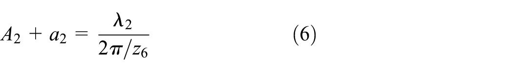
Since face gear 2 and face gear 3 are identical,

From equations (15) to (16), it can be seen that
The SLSC can characterize the non-uniformity of load distribution in each branch of the system. The larger the SLSC, the more uneven the load distribution in each branch of the system. The SLSC more accurately reflects the causes of uneven load in the branch drivetrain, such as assembly errors, support stiffness, torsional stiffness, meshing stiffness, and other factors affecting the load sharing performance.
Static load sharing performance of the system
Table 1 displays the main simulation parameters and operating conditions of the system. From equation (16), it can be seen that the instantaneous load sharing coefficients of split-stage and converge-stage are the same. Therefore, in the example, the SLSC of the split-stage is taken as an example to analyze the load sharing performance of the system.
Main simulation parameters and operating conditions of the system.

In the example, the number of teeth of helical gear 1 and helical gear 6 is odd. When
When there is no error, the instantaneous static load distribution curve of the system is shown in Figure 7. The SLSC curves of the split-stage fluctuates around amplitude 1, and the waveform has a clear meshing periodicity of the split-stage.
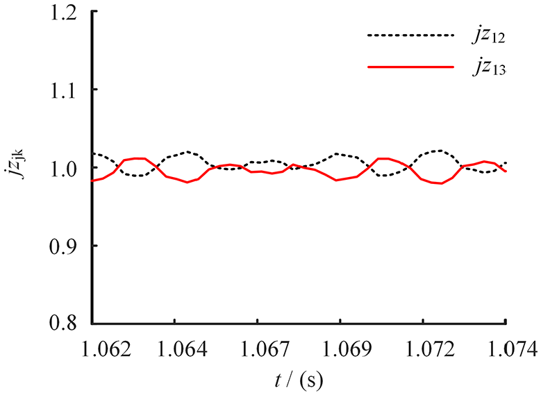
Instantaneous SLSC curves of the system without error.
The shape of the instantaneous average SLSC curves for the converge-stage and the split-stage are the same, but due to the unequal meshing cycles of two stages, the instantaneous average SLSC curves for each cycle are not exactly the same.
The influence of meshing phase differences on the SLSCs
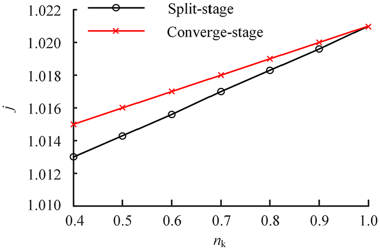
When there is no error, the average SLSC of the system is 1.021. The uneven distribution of two branch loads is caused by the meshing phase differences, but the meshing phase differences have little effect on the average SLSCs. When the phase difference is 0.5, it has the greatest impact on the average SLSC, as shown in Figure 8.

The influence of meshing phase differences
Therefore, to ensure the equal load of two branch diversion system, the first step is to eliminate the influence of the meshing phase differences of each gear pair. For example, when
The impact of assembly errors on the SLSCs
Due to the symmetrical structural parameters of the double branch, the impact of assembly errors on the load sharing performance of face gears 2 and 3 is consistent. Therefore, only one of them can be studied. The impact of assembly errors in the split-stage on the system’s load sharing is shown in Figures 9 and 10.

The impact of assembly errors

The impact of assembly errors
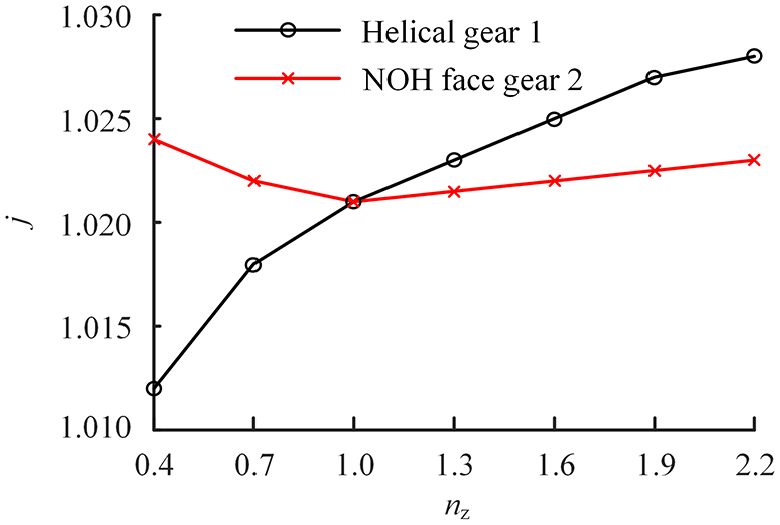
As the assembly errors increase, the SLSCs approximately increase linearly; Under the same assembly errors conditions, the assembly errors of helical gear 1 have a greater impact on the SLSCs than that of face gear 2; In the assembly errors of the split-stage, the shaft angle errors (
The assembly errors of helical gears 4 and 5 can also be studied only one of them. The impact of assembly errors in the converge-stage on the SLSCs is shown in Figure 11.

The impact of assembly errors
As the assembly errors increase, the SLSCs also increase approximately linearly; Under the same assembly errors conditions, the assembly errors of helical gear 6 have a greater impact on the SLSCs than helical gear 4; In the assembly errors of the converge-stage,
The impact of input load on the SLSCs
Figure 12 shows the variation curves of the SLSC with the input load. When there is no assembly error, the average load factor of the system hardly changes with the increase of input load. However, when there are assembly errors in the system, the SLSCs decrease with the increase of input load. For example, when

The impact of input load on the SLSCs.
The influence of multiple of support stiffness on the SLSCs
Figure 13 shows the influence curves of the support stiffness multiple (
The influence of multiple of support stiffness on the SLSCs.
The influence of multiple of torsional stiffness on the SLSCs
Figure 14 shows the variation curves of the SLSC with the multiple of two shafts torsional stiffness (

The influence of multiple of torsional stiffness on the SLSCs.
As the torsional stiffness increases, the SLSC also increases, especially when there are assembly errors, the increase in the SLSC is more significant. By weakening the torsional stiffness of two shafts, the load sharing performance of the system can be effectively improved.
The influence of amplitude multiples of mesh stiffness fluctuations on the SLSCs
Figure 15 shows the variation curves of the SLSC with the amplitude multiple (
The influence of amplitude multiples of mesh stiffness fluctuations on the SLSCs.
Conclusions
(1) The uneven load of the system without error is mainly caused by the meshing phase differences of the split-stage, but the meshing phase differences have little effect on the SLSCs.
(2) Assembly errors have a significant impact on the load sharing performance of the system, especially the shaft angle errors of the split-stage face gear pairs, which have the greatest impact on the SLSCs; The assembly errors of helical gear 1 have a greater impact on the SLSCs than that of face gears 2 and 3, while the assembly errors of helical gear 6 have a greater impact on the SLSCs than that of helical gears 4 and 5.
(3) When there are assembly errors, the input load and torsional stiffness have a significant impact on the SLSCs.
(4) The closer the support stiffness multiple is to 1 multiple, the more symmetrical two branch structures become. Using a symmetrical offset layout of branch structures can ensure that face gear 2 and face gear 3 have the same support stiffness; Consider floating assembly of helical gear 1 to reduce its support stiffness and decrease the SLSCs.
(5) It can be considered to reduce the fluctuation amplitude of the meshing stiffness of the split-stage and converge-stage and lower the system load sharing performance by modifying the tooth surface.
Footnotes
Handling Editor: Chenhui Liang
Declaration of conflicting interests
The author(s) declared no potential conflicts of interest with respect to the research, authorship, and/or publication of this article.
Funding
The author(s) disclosed receipt of the following financial support for the research, authorship, and/or publication of this article: This study is supported by the Guangxi Natural Science Foundation (No. 2022GXNSFBA035574), the National Natural Science Foundation of China (No. 52265006), and the Guangxi Science and Technology Program (No. AD23026183).