
Abstract
This article proposes the application of a profile-shifted grinding disc to generate an offset, non-orthogonal and profile-shifted face gear. A detailed investigation of the modelling, tooth geometry and contact characteristics of the offset, non-orthogonal and profile-shifted face gear has been conducted. The mathematical models of the profile-shifted shaper cutter, profile-shifted pinion, profile-shifted grinding disc and offset, non-orthogonal and profile-shifted face gear are established. Considering the topological modification, the tooth surface equation of the offset, non-orthogonal and profile-shifted face gear is deduced. Based on the undercutting and pointing of the tooth surface, the limiting tooth width of the offset, non-orthogonal and profile-shifted face gear is determined, and a mathematical model of tooth contact analysis of the offset, non-orthogonal and profile-shifted face gear drive is established with the alignment errors. Using the approach presented in this article, an example of an offset, non-orthogonal and profile-shifted face gear drive and analytical results are presented.
Keywords
Introduction
Face gear drives are a new type of gear transmission consisting of a cylindrical pinion and a conjugated face gear with the advantages of low noise, light weight and convenient installation compared with bevel gear drives.1,2 When machining the face gear, according to the position relationship between the cutter and the machined face gear, the two axes can be divided into vertical intersection, non-vertical intersection, vertical staggered and non-vertical staggered for four types of situation. The corresponding face gears are called an orthogonal face gear, non-orthogonal face gear, offset orthogonal face gear and offset non-orthogonal face gear. They have broad applications in the field of industrial and aerospace power transmissions and are a research focus in gear transmission. 3 Litvin et al.4–6 investigated the generation principle, tooth geometry, meshing simulations, contact characteristics and stress analysis of orthogonal face gear drives in depth and made significant particularly important progress in promoting face gear development. Zhang and Wu 7 presented a deep investigation on the generation, tooth geometry and contact characteristics of offset face gear drives, and the design criteria and an algorithm for the tooth contact analysis (TCA) of offset face gears were established. Barone et al. 8 studied the effect of misalignment and profile modification on the behaviour of a face gear drive by integrating a finite element analysis (FEA) code and a 3D CAD system, using an automated contact algorithm and contact elements. An approach was proposed by Zanzi and Pedrero 9 to generate a topologically modified pinion for face gear drive using a plunging disc, which reduced sensitivity and avoided edge contact in the presence of misalignments. Tsay and Fong 10 developed a new modification method for the moulded face gear drive based on the application of a skew double crowning on the tooth surface of the face gear to control the transmission characteristics and the contact pattern. More recently, Li et al. 11 proposed a strength calculation solution of face gear drives based on ISO 6336 standard and an equivalent face gear tooth, and predicted the influences of geometric parameters on the strengths. Stadtfeld, 12 Tang et al., 13 Wang et al.14,15 and Shen et al. 16 have done some important work on the precision machining methods of face gear to meet the tough requirements of high-power applications, including hobbing, milling, honing and grinding. In addition, a new type of face gear drive consisting of a non-circular gear and a curve-face gear with intersecting axes was proposed by Lin and colleagues,17,18 which integrated the features of curve-face gear and non-cylindrical gear and achieved variable ratio transmission of power and motion.
However, the existing research just focuses on the first three types of face gears mentioned above, while the more complex and universal face gear is the offset non-orthogonal face gear, which is neglected and yet to be further investigated. The design of an offset non-orthogonal face gear drive can provide a flexible layout option for the overall design of aerospace power transmissions, which is advantageous for achieving the most compact layout in a narrow space. In addition, the profile-shifted involute cylindrical gear can effectively improve gear transmission performance, where the positive gear can reduce the size and weight of the machine, avoid undercutting and improve the bending strength of the tooth root and the contact strength of the tooth surface.19,20 However, since the face gear teeth are distributed on the end surface of the gear blank, it is impossible to obtain the profile-shifted tooth surface of the face gear using the traditional method of changing the relative position of the cutting tool and the gear blank. To achieve the profile-shifted face gear, the structural parameters of the cutting tool must be changed, such as using a profile-shifted shaper cutter.
In this article, detailed research on an offset, non-orthogonal and profile-shifted (ONP) face gear drive is performed. The specific details are as follows: (1) using the grinding disc (hereinafter referred to as profile-shifted grinding disc) with the same tooth shape as the profile-shifted shaper cutter to obtain the profile-shifted face gear with fillet surface, establishing a unified model of ONP face gear drives; (2) determining the limiting tooth width of the ONP face gear based on the undercutting and pointing of the tooth surface and (3) considering the alignment errors, establishing a mathematical model of TCA of the ONP face gear drive to study the meshing characteristics.
Model of ONP face gear drives
Generation principle of ONP face gear
The presented method of a grinding ONP face gear is based on the application of a profile-shifted grinding disc, and the machining process is based on the simulation of meshing the face gear with a single tooth of a profile-shifted shaper cutter. The generation principle is shown in Figure 1. The movable coordinate systems Sg, Ss and S2 are rigidly connected to the profile-shifted grinding disc, the profile-shifted shaper cutter and the ONP face gear, respectively. The fixed coordinate systems Sr is connected to the frame of the grinding machine. The line segment OrOs is represented by L0.

Generating ONP face gear by profile-shifted grinding disc.
When the relative position is invariable, the positive profile-shifted grinding disc processes the corresponding negative profile-shifted face gear, and the negative profile-shifted grinding disc processes the corresponding positive profile-shifted face gear. According to the meshing principle, the negative profile-shifted face gear can be meshed with the corresponding positive profile-shifted pinion; in contrast, the positive profile-shifted face gear can be meshed with the corresponding negative profile-shifted pinion. For convenience, all profile-shifted coefficients x represent the profile-shifted coefficient of the profile-shifted face gear pair. For example, x = –0.2 (negative profile-shifted) indicates that the profile-shifted coefficient of the pinion is −0.2, and the profile-shifted face gear is generated by a grinding disc with a profile-shifted coefficient of −0.2.
Tooth surface of profile-shifted shaper cutter and profile-shifted pinion
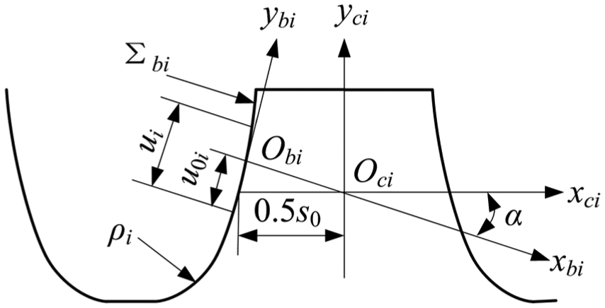
The transverse profiles of the rack cutter to generate the profile-shifted shaper cutter tooth surface and profile-shifted pinion tooth surface are mismatched parabolic profiles that deviate from traditional straight-line profiles, as shown in Figure 2. Sci and Sbi (where i = 1 and s specify the parameters to generate the pinion and shaper cutters, respectively) are the fixed coordinate systems, s0 is the circular pitch, α is the profile angle of the rack cutter and ρi is the fillet circle of the radius. The rack cutter surface Σ bi can be represented in the coordinate system Sci by the equations


where ui and li represent the rack cutter surface parameters and aci is the parabola coefficient. The parameter u0i controls the tangent point between the parabolic profile and the traditional straight-flank surface. The 4 × 4 matrix

Rack cutter with mismatched parabolic profile.
The unit normal vectors of the rack cutter surface are

The tooth surface of the profile-shifted shaper cutter and profile-shifted pinion denoted, respectively, by Σ s and Σ1 are the envelope for the family of surfaces Σ bs and Σb1, as shown in Figure 3. The movable coordinate systems Sbi and Si are connected to the rack cutter and gear, and the fixed coordinate system Sdi is connected to the frame of the cutting machine. φi is the rotational angle, ri is the reference radius and m is the module. The theoretical position and unit normal vectors of the tooth surface of the profile-shifted shaper cutter and profile-shifted pinion in the coordinate system Si can be expressed as follows


where fi represents the equation of meshing and Rcix and Rciy are the two coordinate components of

Applied coordinate systems for generation of profile-shifted shaper cutter and profile-shifted pinion.


Tooth surface of profile-shifted grinding disc
The generating line of the profile-shifted grinding disc


where two 4 × 4 matrices,

Determination of profile-shifted grinding disc.
The matrix

The matrix

Tooth surface of ONP face gear
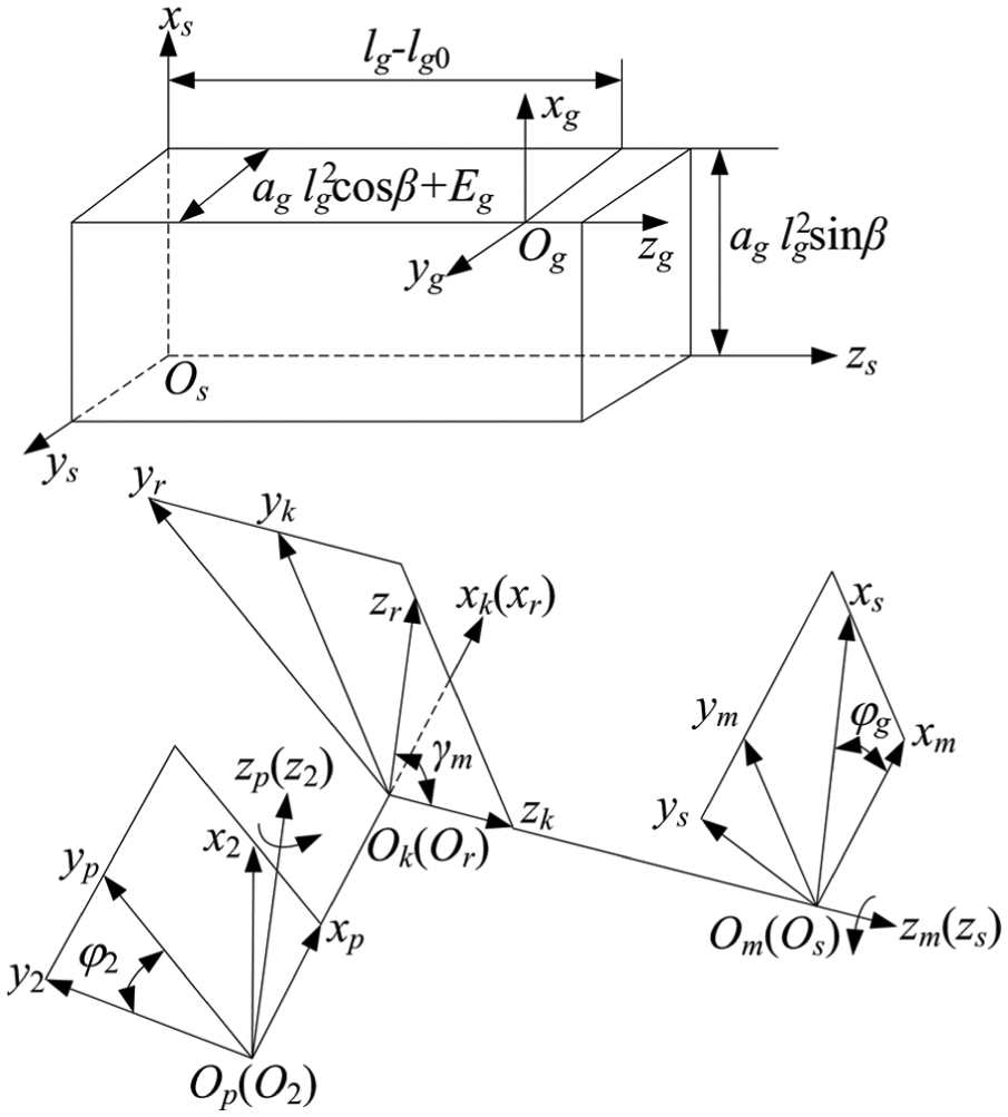
The applied coordinate systems for ONP face gear generation are shown in Figure 5. The fixed coordinate systems Sm, Sk and Sp are connected to the frame of the grinding machine. The ONP face gear tooth surface Σ2 is the envelope of the family of surface Σ g . ag and lg0 are the motion parameters of the centre of the profile-shifted grinding disc along the parabola g, β (generally taken as 0) is the angle between a plane containing the parabola g and the axial cross-section of the profile-shifted grinding disc, and the three of them together represent the axial modification parameters of the ONP face gear. φg is the swing angle of the profile-shifted grinding disc and φ2 is the rotational angle of the ONP face gear. The common perpendicular of the two axes z2 and zs is OpOk and equals the offset distance E.
Applied coordinate systems for the generation of ONP face gear.
The position and unit normal vectors of the ONP face gear tooth surface Σ2 in the coordinate system S2 can be expressed as follows

where the 4 × 4 matrix


Fillet surface of ONP face gear
The shape of the ONP face gear fillet surface is important for bending strength and stress concentration of the tooth root. For a larger radius of curvature and a higher bending strength, both fillets of the profile-shifted grinding disc are designed as an arc of radius ρg centred at the origins O and O′, as shown in Figure 6. Taking the right-hand side as an example, M1 is the tangential point of the arc and tooth profile, and M2 is the tangential point of the arc and addendum circle. Based on the above, the position and unit normal vectors of the arc M1M2 at point M1 are

where rs is the reference radius of the profile-shifted shaper cutter, Rsx(us) and Rsy(us) are the two coordinate components of

Fillet of profile-shifted grinding disc.
The position and unit normal vectors of the arc M1M2 at an arbitrary point in the coordinate system Ss can be expressed as follows

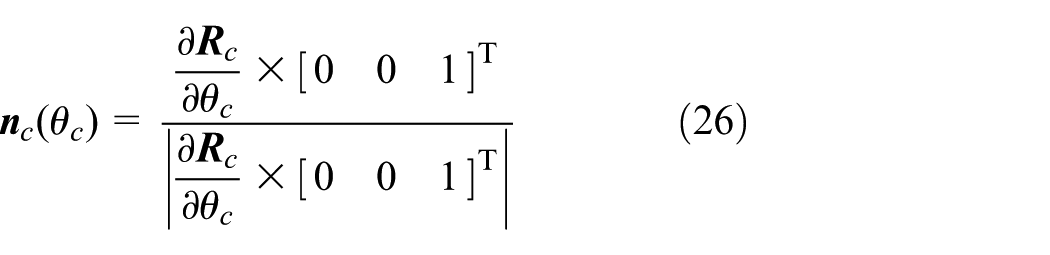
where θc is the arc parameter and θ1 ≤ θc ≤ θ2.
The position and unit normal vectors of the profile-shifted grinding disc fillet surface Σ g in the coordinate system Sg can be expressed as follows


The ONP face gear fillet surface is the envelope to the family of surfaces generated by the arc M1M2 in the profile-shifted grinding disc in the coordinate system S2. Similarly, the profile-shifted pinion fillet surface is the envelope to the family of surfaces generated by the arc of radius ρ1 in the coordinate system S1, as shown in Figure 2.
Limiting tooth width of ONP face gear
Undercutting and pointing of the tooth surface Σ2 are negative phenomena that appear in the generation of the ONP face gear tooth, which can be avoided by limiting the tooth width. According to the relative position of the profile-shifted shaper cutter and the ONP face gear when generating, L1 and L2 are defined as the inner and outer radii of the ONP face gear and B is defined as the tooth width, as shown in Figure 7. Consider the relationship of space geometry, L1, L2 and B satisfy the following relations

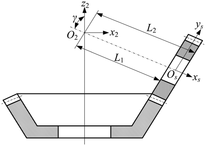
Geometric dimensions of ONP face gear.
Avoidance of undercutting
According to the general approach for determining the non-undercutting conditions of a spatial gear proposed by Litvin and Fuentes, 21 limiting the profile-shifted grinding disc tooth surface Σ g is necessary to avoid undercutting of Σ2. The limiting line on Σ g is based on the following conditions

where

where
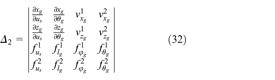
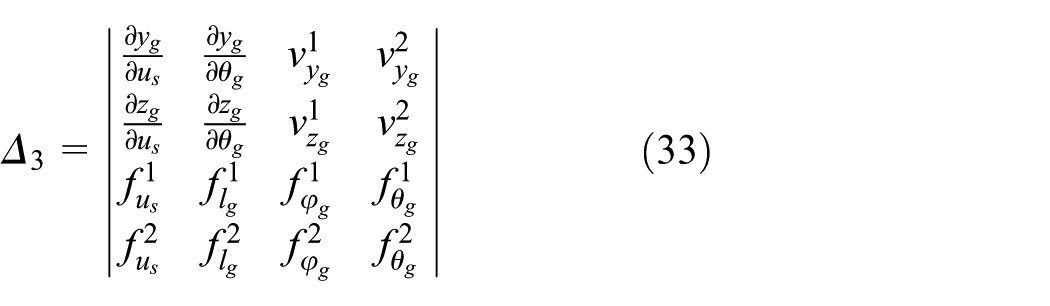
Equations (24) and (30) simultaneously determine the critical point of undercutting

where
Due to the asymmetry of the ONP face gear tooth surfaces, there are two limiting inner radii,

Avoidance of pointing
Pointing of teeth is determined by considering the tooth thickness at the top of the tooth in the ONP face gear being equal to zero. Assuming that

where the superscripts or subscripts l and r indicate the left- or right-hand side of the tooth, respectively.
Equation (36) can be used to determine the position vector of the critical point of pointing

The limiting tooth width of the ONP face gear is represented as follows

The mathematical model of TCA of ONP face gear drive
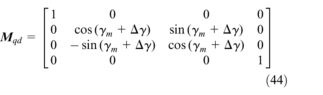
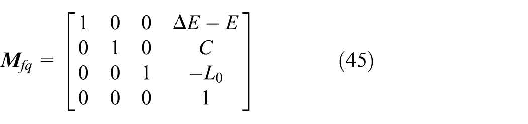
The coordinate systems applied for TCA of the ONP face gear drive are shown in Figure 8. The movable coordinate systems denoted by S1 and S2 are rigidly connected to the profile-shifted pinion and the ONP face gear, respectively. The rotational angles of the profile-shifted pinion and the ONP face gear are Φ1 and Φ2, respectively. Two surfaces, Σ1 and Σ2, are meshed in the fixed coordinate system Sf. The fixed coordinate systems Sq, Sd and Se are applied to simulate the axial displacement error Δq, offset error ΔE and shaft angle error Δγ, respectively. The parameter C is the shortest distance between the reference radii of the profile-shifted pinion and the profile-shifted shaper cutter and γf is the actual angle defined as γf = γm + Δγ

where the 4 × 4 matrices
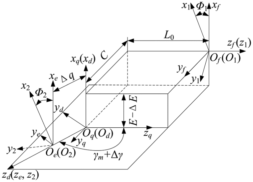
Coordinate systems for gear meshing.
The matrix

The matrix


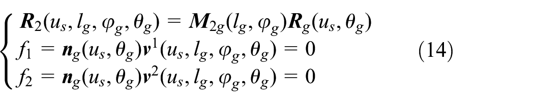
Since the normals are unit vectors, equation (39) yields a system of five independent nonlinear scalar equations with eight unknowns, Φ1, u1, l1, us, lg, φg, θg and Φ2. Considering the equations of meshing, f1 and f2, lg and φg can be eliminated. Then, if one unknown, such as Φ2, is chosen as the input parameter with a certain step length for changing its numerical value, the other parameters can be solved from the nonlinear equation system. Furthermore, using the TCA programme according to the general approach in Litvin and Fuentes 21 and Simon, 22 the position vector, normal vector, principal curvatures and relative principal direction at an instantaneous point of contact can be calculated.
Numerical examples and discussion
The parameters of the ONP face gear drive are listed in Table 1. Given two different parameter sets, the limiting tooth length and tooth geometry of two typical ONP face gears are illustrated in Figure 9(a), where x = 0.2, E = –16 mm andγ = 120°, and in Figure 9(b), where x = –0.2, E = 16 mm and γ = 60°. As shown in Figure 9, calculating the limiting inner and outer radii of an ONP face gear and designing an ONP face gear of the gear drive without undercutting and pointing is possible. The two tooth branches of the ONP face gear are asymmetrical, and the fillet surfaces of the two tooth surfaces are not equal in size. If no tooth undercutting is observed, the working surfaces and fillet surfaces of the ONP face gear are tangential. For a negative offset (E < 0), the limiting inner radius of the right tooth surface,
ONP face gear drive parameters.

ONP: offset, non-orthogonal and profile-shifted.

Geometry of two typical ONP face gears: (a) x = 0.2, E = –16 mm and γ = 120°; (b) x = –0.2, E = 16 mm and γ = 60°.
The influences of the shaft angle γ, shaft offset E and profile-shifted coefficient x on the two limiting radii and the limiting tooth length of the ONP face gear are illustrated in Figures 10–12, respectively. The shaft angle, shaft offset and profile-shifted coefficient have great influence, especially the shaft angle. When the shaft angle γ increases from 60° to 120°, the two limiting radii and the limiting tooth length significantly decrease first and the two limiting radii reach a minimum value and increase with a small amplitude, while the limiting tooth length reaches a minimum value and significantly increases, and the critical shaft angle of decrease and increase is not 90°. The two limiting radii and the limiting tooth length increase approximately linearly with increasing profile-shifted coefficient. The influence of shaft offset is divided into three cases in terms of the shaft angle: when the shaft angle is small (such as γ = 60°), as the shaft offset increases, the two limiting radii increase and the limiting tooth length is approximately unchanged at first and then slowly increases. When the shaft angle is equal to 90°, as the shaft offset increases, the two limiting radii also increase, but the limiting tooth length decreases approximately linearly. When the shaft angle is large (such as γ = 120°), as the shaft offset increases, the limiting inner radius increases with a large amplitude, but the limiting outer radius decreases with a small amplitude, resulting in a gradual decrease in the limiting tooth length.

Influence of shaft angle on the two limiting radii and limiting tooth length with x = 0 and E = 0 mm: (a) Lmin and Lmax; (b) Bmax.

Influence of shaft offset on the two limiting radii and limiting tooth length with x = 0: (a) Lmin and Lmax; (b) Bmax.

Influence of profile-shifted coefficient on the two limiting radii and limiting tooth length with E = 0 mm: (a) Lmin and Lmax; (b) Bmax.
The influences of the profile-shifted coefficient and shaft offset on the contact performance are shown in Figure 13 where γ = 60°, L1 = 157 mm, L2 = 179.5 mm and B = 22.5 mm. The profile-shifted coefficient does not change the contact rule of the gear pair, that is, the shape and location of the contact pattern are unchanged, the contact path is still perpendicular to the tooth root of the ONP face gear, and the contact ratio remains at approximately 1.5. The shape and location of the contact pattern on the left and right tooth surfaces of the ONP face gear are asymmetric. The offset makes the contact pattern on the left of the tooth surface move towards the toe and the contact pattern on the right of the tooth surface move towards the heel. The contact path is no longer perpendicular to the tooth root but is inclined at an angle, and the inclined directions on the left and right teeth are opposite. The larger the shaft offset, the more inclined the contact path, the more obvious the contact pattern on the left tooth surface moves towards the toe, and the more obvious the contact pattern on the right tooth surface moves towards the heel. The contact pattern areas on the two branches of the tooth decrease when E ≠ 0, especially for a large E, the decrease on the left tooth surface is obvious. The contact ratio of the left tooth surface is not sensitive to the shaft offset and almost unchanged, but for the right tooth surface the contact ratio decreases as the shaft offset increases.

Contact patterns of non-orthogonal, offset and profile-shifted face gear drives: (a) x = 0.2, E = 0 mm;(b) x = 0, E = 0 mm; (c) x = –0.2, E = 0 mm; (d) x = –0.2, E = 6 mm; (e) x = –0.2, E = 11 mm and (f) x = –0.2, E = 16 mm.
In addition, Figure 13 also shows that both the positive profile-shifted coefficient and shaft offset increase the limiting outer radius with γ = 60°.
The influences of alignment errors and tooth modifications on the contact performance are shown in Figure 14, where the geometric parameters are the same as in Figure 13(f). The positive offset error ΔE makes the contact pattern on the left tooth surface move towards the heel and the contact pattern on the right tooth surface move towards the toe, but the positive axial displacement error Δq and the positive shaft angle error Δγ both make the contact patterns on the two branches of the tooth move towards the heel. Figure 14(d)–(f) shows that if the modification parameters of the ONP face gear are reasonable when there are various errors, such as acs =–0.002, ucs = 2 mm, ag =–0.001 and lg0 = 1 mm, the topological modification can move the contact patterns of the two branches of the tooth towards the middle of the tooth width, further incline and lengthen the contact path and increase the contact ratio, so that the meshing performance of the ONP face gear drive is effectively improved.

Influence of alignment errors and tooth modifications on the contact performance: (a) ΔE = 0.25 mm; (b) Δγ = 0.07°;(c) Δq = 0.35 mm; (d) Δq = 0.35 mm, acs = –0.002, ucs = 2 mm, ag = –0.001 and lg0 = 1 mm; (e) Δq = 0.35 mm and ΔE = 0.25 mm;(f) Δq = 0.35 mm, ΔE = 0.25 mm, acs = –0.002, ucs = 2 mm, ag = –0.001 and lg0 = 1 mm.
Conclusion
In this article, an ONP face gear generated by a profile-shifted grinding disc is introduced and the tooth geometry and contact characteristics of ONP face gears are studied. First, a unified model of ONP face gear drives is established and the tooth surface equations of the profile-shifted shaper cutter, profile-shifted pinion, profile-shifted grinding disc and ONP face gear are deduced. Second, the limiting radii and tooth length of the ONP face gears are determined to avoid tooth undercutting and pointing. Then, considering alignment errors, a mathematical TCA model of the ONP face gear drive is established.
Some conclusions can be drawn from the simulation as follows:
The shaft angle γ, shaft offset E and profile-shifted coefficient x have different influences on the two limiting radii and the limiting tooth length of the ONP face gears. Using the larger profile-shifted coefficient x and the larger or smaller shaft angle γ is advantageous for obtaining a larger limiting tooth width of the ONP face gears, but the influence of shaft offset is divided into three cases in terms of the shaft angle. For the commonly used shaft angle (γ = 90°), the shaft offset decreases the limiting tooth width.
The profile-shifted coefficient does not change the contact rule of the gear pair. The shape and location of the contact pattern are unchanged, and the contact path remains perpendicular to the tooth root of the ONP face gear. Shaft offset has a large influence on the contact pattern of the two branches of the tooth and incline the contact path at an angle.
The alignment errors can move the contact pattern of the two tooth branches along the width of the teeth; however, the influence of the offset error ΔE on the contact pattern is different from that of the axial displacement error Δq and the shaft angle error Δγ. The topologically modified tooth surface of the ONP face gear by implementing profile-shifted grinding disc profile modification and centre movement can effectively improve the contact pattern and meshing performance.
Footnotes
Handling Editor: Davood Younesian
Declaration of conflicting interests
The author(s) declared no potential conflicts of interest with respect to the research, authorship and/or publication of this article.
Funding
The author(s) disclosed receipt of the following financial support for the research, authorship and/or publication of this article: This work was supported by the National Natural Science Foundation of China (No. 51375384), the Aeronautical Science Foundation of China (No. 2015ZB 55002) and the Natural Science Foundation of Henan Province (No. 182300410239).