
Abstract
The cutting characteristics observed in machining processes are significantly influenced by a combination of various dynamic parameters as well as the overall machine tool system in use. This paper introduces a cutting force coefficient mining method that considers the impact of tool vibration and machine tool system. Firstly, a basic cutting model was established based on orthogonal cutting. Obtained the cutting force coefficient for orthogonal cutting. Subsequently, the dynamic undeformed chip thickness data was integrated to reflect the influence of tool vibration during the machining process. Additionally, due to the replacement of the machine tool, correction factors have been introduced to consider the impact of the machine tool system. Finally, a comparative analysis was conducted with other methods for calibrating cutting force coefficients. The prediction accuracy of the proposed model has been validated, demonstrating its effectiveness in accurately predicting dynamic cutting forces.
Introduction
The measurement of cutting force has important and extensive applications in industry and research fields. The measurement and prediction of cutting force are the important parameters for evaluating the machining. Accurately predicting cutting force remains an urgent problem to be solved.1–3 There are many methods for predicting cutting forces in existing research.4,5
Among the analytical models, the cutting force model proposed by Altintas 6 is the most commonly used. In this type of model, the cutting force coefficient needs to be determined in advance. There are two classic methods to obtain the cutting force coefficient. One is to use orthogonal cutting to convert to milling, and the other is to quickly calibrate through experimental methods in milling. 7
The most classic cutting force prediction model is that Budak et al. 8 utilized orthogonal cutting parameters for a milling force prediction. Recent advancements have introduced various new methodologies.9–11 For instance, Shi et al. 12 used the time–frequency domain identification method along with a reaction force model to calculate coefficients. Chen et al. 13 enhanced orthogonal transformation accuracy by factoring in tool vibration. But the disadvantage of this modeling method is that it needs to consider the processing conditions and the influence of different machine tool.
In experimental calibration method, cutting forces can be derived with coefficients calibrated through testing.14–16 Pérez-Ruiz et al. 17 discussed the influence of the instantaneous contact area between cutting tool and workpiece on the shear coefficient in milling processing. Cai et al. 18 and Yao et al. 19 combined cutting edge geometry with dynamic machining characteristics using finite element analysis for a comprehensive impact assessment. Yuan et al. 20 correlated machining vibration data with cutting position to analyze its effect on cutting forces. Chen et al. 21 focused on the geometric contact between tool and workpiece to develop a dynamic prediction model for undeformed chip thickness. Furthermore, Deepanraj et al. 22 proposed a mechanical model of milling process based on the finite element idea, and proposed a method to predict the coefficient of milling force. However, existing models are based on static or instantaneous cutting, lacking the influence of the entire machining process, resulting in data that cannot be reused.
Since cutting parameters in milling are time-dependent, existing prediction methods often overlook the effects of these parameters and machine tool systems, causing significant discrepancies between predicted models and actual measurements. This paper presents a method for predicting cutting force coefficients that includes the effects of tool vibration and machine tool systems. Initially, a basic cutting model using orthogonal cutting is established. By incorporating collected dynamic undeformed chip thickness data, the influence of tool vibration is integrated into the data mining model. Machine tool correction coefficients are then introduced to account for system impacts. Experiments validate the predictive accuracy of the proposed model, demonstrating its ability to accurately forecast dynamic cutting forces.
Modeling of cutting force coefficient mining method
This section mainly consists of three parts. Firstly, the identification of cutting force coefficients under orthogonal cutting. Then there is the transition from orthogonal cutting to milling machining. During the conversion process, it is necessary to consider the effects of tool vibration and machine tool system. The second part is the modeling of cutting force considering tool vibration. Finally, mining the cutting force coefficient considering the influence of the yellowing system.
Identification model of cutting force coefficients through basic cutting test
In orthogonal cutting, the following expressions can be used to describe cutting force 6 :

where
Model for transformation from orthogonal cutting to milling
In order to make better use of the orthogonal cutting data resources, the cutting width

where

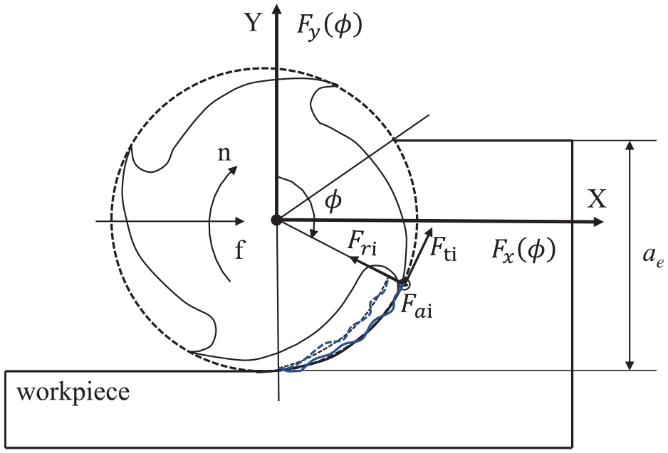
Milling process.
Tangential (

In one cycle, the cutting force is calculated as follows:

where

Cutting force prediction model with tool vibration
Tool vibration changes the position of the tool, which in turn changes the undeformed cutting thickness during the cutting process of the tool, thereby bringing about dynamic changes in the cutting force, see Figure 2. The newly machined surface generated by the tool cutting when there is no vibration, that is, the black solid line. When the tool vibrates, the cutting edge causes the freshly machined surface to exhibit a corrugated appearance, as shown by the blue solid line.
Dynamic undeformed chip thickness.
To incorporate the effects of tool vibration in cutting force prediction, a dynamic increment can be introduced on the theoretical feed per tooth:

where
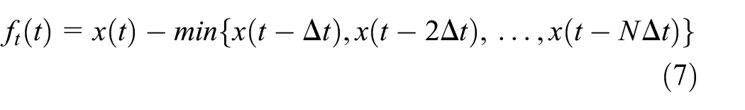
So as to obtain the dynamic undeformed chip thickness:

Substituting it into formulas (3) and (4), the cutting force considering the tool vibration can be obtained.
Cutting force mining method considering the impact of machine tool system
The force affected by the machine tool can be expressed as:

where
Due to the large number of associated parameters, it is difficult to accurately identify. Introduce two coefficients to simplify the model representation:

where
In summary, the cutting force model is represented as:

Experimental verification and discussion
Data acquisition and coefficient identification
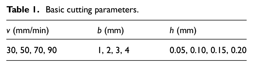
Orthogonal cutting experiments of TC4 were conducted on a custom machine using the Kistler 9272 dynamometer (see Figure 3) with parameters are shown in Table 1.

Setup of basic cutting test.
Basic cutting parameters.
The cutting force obtained from the test is shown in Figure 4.
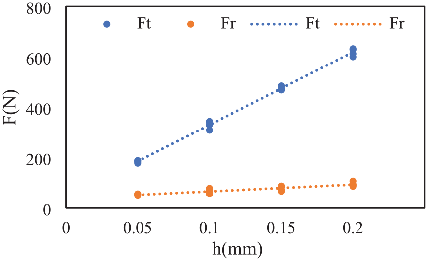
Cutting forces measured during basic cutting tests.
The cutting force coefficients of orthogonal cutting identified by the fitted curve are shown in Table 2.
Cutting force coefficients identified by basic cutting.

It is easy to observe from the prediction accuracy in Table 3 that the average prediction error is about 3%.
Prediction error of cutting force (basic cutting).

Cutting force prediction considering tool vibration
The relevant information in the test is as follows (see Figure 5 and Table 4): the machine model is DMU70V machining center with a Kistler 9272. The tool model is SN5204P. The experimental method is to fix the workpiece on the force measuring instrument and the spindle drived the tool to move. Cutting force and tool vibration were collected during the machining process.

Experimental setup.
Cutting parameters in calibration tests.

The cutting force coefficient model obtained in 3.1 is applied to the prediction of milling force, and the tool vibration data measured by the acceleration sensor in the test is superimposed, as shown in the Figure 6. The speed direction of tool vibration is basically consistent with the direction of cutting force related to the period. However, even though there is a certain pattern in the vibration of the cutting tool, the pattern is not very strict. The non negligible additional feed rates in the x and y directions caused by tool vibration indicate that tool vibration has a significant impact on the dynamic undeformed chip thickness. So, it is necessary to add the influence of tool vibration when cutting the cutting force coefficient. By combining real-time acceleration signals with time, the actual chip thickness during machining can be obtained, and then the cutting force can be predicted using equations (3) and (4).

Acceleration signals of
Comparing the cutting force model that accounts for tool vibration with the measured cutting force results, depicted in Figure 7, reveals a notable discrepancy between predicted and measured values. This difference arises because the machine tool system’s influence is not included in the transition from orthogonal cutting to milling.

Comparison of cutting force in
Identification of machine tool correction coefficients considering tool vibration
The calibration coefficient can be identified through tests, and the results are shown in Figure 8. From the figure, it can be observed that the values fluctuate within a stable region. Therefore, take the average value within the stable interval as its accurate value, and the results are shown in Table 5.

Correction coefficients: (a) tangential and (b) radial.
The values of correction coefficients.

The predicted and measured results under different cutting parameters are shown in Figure 9. The experimental value is represented by a blue curve. The predicted values obtained by the proposed method are represented by a red curve. The predicted values of tool vibration and the predicted cutting force of the orthogonal cutting conversion method are represented by yellow and green solid lines, respectively. First of all, the test data in the figure verifies that the cutting force prediction model established in consideration of machine tool factors is very consistent with the cutting force recorded in the test. The prediction result with the machine tool correction coefficients is significantly better than the result only considering the tool vibration, especially in the middle and end of the tooth cutting. Due to the uncertain factors in the system processing, the deviation is acceptable.
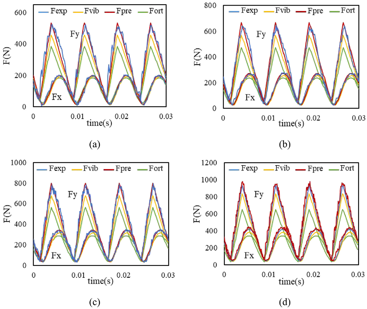
Comparison of cutting force: (a)
The impact of the machine tool system in the cutting force coefficient prediction model
To further compare the impact of machine tool factor on the results of cutting force coefficients, the following will compare the cutting force coefficients obtained under different methods. Extensive experimental data has been processed, resulting in multiple sets of cutting force coefficients. Three methods compared are shown in the Table 6.
Different methods to identify the cutting force coefficients.

According to different identification methods of cutting force coefficients, the cutting force coefficients obtained by tests at different axial depths of cut are plotted in the Figures 10 and 11. Under different cutting conditions, the machine tool system has different effects on the identification results. Such as the average value of

Comparison of three methods under

Comparison of three methods under
Comparing Figures 10 and 11, at different speeds, the identification results of cutting force coefficients shows the same trend of change, and machine tool has a greater impact on the identification of the shear force coefficients, especially in some tests, the shear force coefficient has increased significantly (e.g.
In order to better compare the identification results of the cutting force coefficients, especially the influence of the identification quality, the error analysis of the predicted cutting force obtained under the three methods and the actual cutting force is carried out (see Table 7).
Verification experimental parameters of prediction model.

The average test error of the model is defined as:

where
Table 8 lists the prediction errors of the three models. From the table, Model A shows average prediction errors of 18.94% and 25.93% in x and y directions, while the prediction errors of Model B are 12.7% and 13.11%. The average prediction error of
Errors of cutting force prediction in three methods.

Figure 12 compares the cutting force prediction errors of three methods. Model A shows an average prediction error of about 26%, while Model B, which accounts for tool vibration, has an average error of about 12%. The method proposed in this paper achieves an average error of around 6%, and the prediction error is significantly reduced. The prediction accuracy of the cutting force has been greatly improved to ensure the accuracy of the prediction.
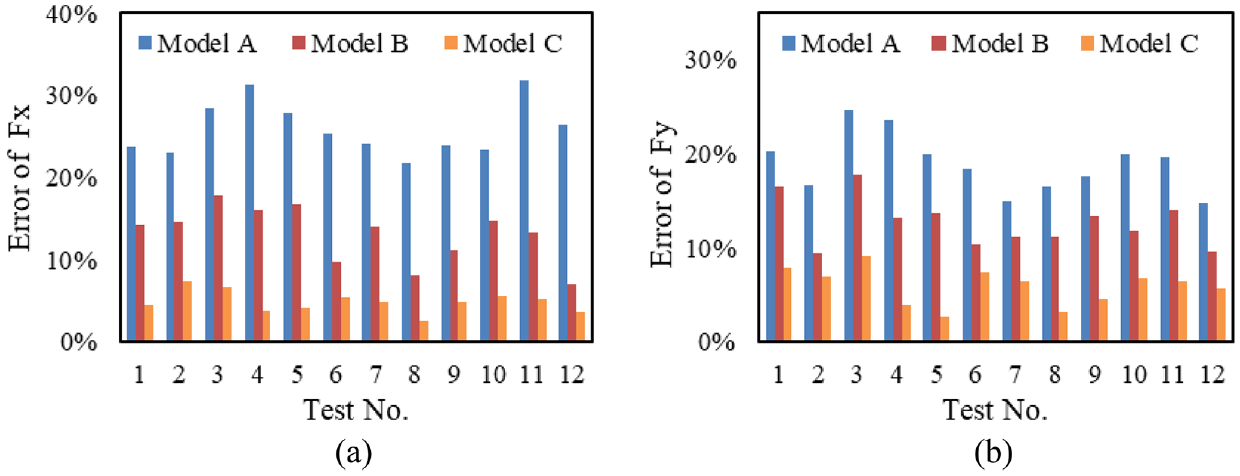
Comparison the errors of three methods: (a) x-direction and (b) y-direction.
Conclusions
This paper proposes a cutting force coefficient mining method that considers the influence of tool vibration and machine tool system to improve the prediction accuracy of cutting force. Some important conclusions are as follows:
By introducing dynamic undeformed chip thickness, the influence of tool vibration on cutting force was analyzed, thereby improving the prediction accuracy of cutting force.
By introducing machine tool correction coefficients, the identification accuracy of cutting force coefficients has been improved. Compared with the prediction method that does not consider tool vibration and machine tool system, the prediction accuracy in this paper has significantly improved by 50%–76%.
The method presented in this paper provides the possibility for data conversion between different machine tools. Meanwhile, it can also be applied to predict physical quantities in other cutting processes.
However, due to limited experimental conditions, the influence of tool wear on cutting force in actual machining was not taken into account. We will continue to study the role of tool wear in mining cutting force coefficients in the future.
Footnotes
Handling Editor: Sharmili Pandian
Author contributions
Conceptualization, X.C., Q.W., W.C., and Y.H.; methodology, X.C., Q.W., and W.C.; software, X.C., Q.W., and W.C.; validation, X.C., Q.W., formal analysis, X.C., Q.W., J.S., and H.G.; investigation, X.C. and Q.W.; resources, H.G.; data curation, X.C., Q.W., and W.C.; writing – original draft preparation, X.C.; writing – review and editing, X.C., Q.W., and Y.H.; visualization, X.C., Q.W., and Y.H. All authors have read and agreed to the published version of the manuscript.
Declaration of conflicting interests
The author(s) declared no potential conflicts of interest with respect to the research, authorship, and/or publication of this article.
Funding
The author(s) disclosed receipt of the following financial support for the research, authorship, and/or publication of this article: This study is co-supported by the National Natural Science Foundation of China (52305446), the Project of Changzhou Basic Research Program (No. CJ20235067), the general project of basic science (natural science) research in colleges and universities of Jiangsu Province (No. 24KJD460001), and the Open Project of the Key Laboratory of High Performance Manufacturing for Aero Engine (Northwestern Polytechnical University) (No. HPM-2022-01).