
Abstract
Recently, the intelligent systems of technology have become one of the major items in the development of machine tools. One crucial technology is the machinery status monitoring function, which is required for abnormal warnings and the improvement of cutting efficiency. During processing, the mobility act of the spindle unit determines the most frequent and important part such as automatic tool changer. The vibration detection system includes the development of hardware and software, such as vibration meter, signal acquisition card, data processing platform, and machine control program. Meanwhile, based on the difference between the mechanical configuration and the desired characteristics, it is difficult for a vibration detection system to directly choose the commercially available kits. For this reason, it was also selected as an item for self-development research, along with the exploration of a significant parametric study that is sufficient to represent the machine characteristics and states. However, we also launched the development of functional parts of the system simultaneously. Finally, we entered the conditions and the parameters generated from both the states and the characteristics into the developed system to verify its feasibility.
Introduction
Tool change is one of the most commonly performed actions in machine processing. During a tool change, the position of the tool change arm shifts, which causes the principal axle of the tool to be inappropriately positioned and, therefore, results in damages to the principal axle bearing or even problems such as knife falling or processing hole slanting due to a poor principal axle broaching action. Currently, in response to this problem, machine products in the market use an air pressure seal confirmation method to perform accuracy detection for the state of the principal axle holding tool. As this method requires a high precision in the mechanical component, it cannot be used for machines of any mode widely, and it does not possess the detection capability for inappropriate positioning of the principal axle during an automatic tool changer (ATC) process. Therefore, another solution must be sought.
Among the various factors of mechanical state detection, only vibration detection has its own advantage relative to the foregoing problems (e.g. an insufficient resolution of the current, an excessive noise interference from the environment, the inconvenience of installation for mechanics, or shift detection), and therefore, it is the most commonly used technology. However, due to the differences between the structures and desired properties of machines from different factories, it is hard to adopt one common device. Even if an entire system is purchased to be used in the future, there are still subsequent maintenance and customization service issues for the system.
This study aims to produce a set of automatic tool changer monitoring systems (ATCMS). This system is able to analyze the physical phenomena caused by a machine’s ATC using a signal process method and to assess the current functionality. In addition, this system can compare the current state resulting from the tool change with the normal and functioning characteristic function model using a statistical and classification analysis. This system is able to diagnose the probable breakdown situation resulting from the changed tool or the principal axle, determine the response measure required to prevent the spreading of low quality when the incident occurs, and thereby increase the credibility and production efficiency of the mechanical equipment.
Literature review
In recent years, with recent technological improvements, an increasing emphasis is placed on smart technology. With great effort from the American Intelligent Maintenance System (IMS) Center, research related to intelligentization has been collated to a single clear research theme. In 2004, Lee et al. 1 suggested applying smart technology to various processing manufacturing equipment.
In 2006, Lee et al. 2 reported the main structure for a smart maintenance system. In studies of smart technology, the retrieval of characteristics and the analysis process play important roles. Their main steps include the transfer of the signal, characteristics retrieval, and quality estimation. The method chosen for each step can differ based on its individual features and requirements. In the research of the past 20 years, as computerized calculation developed rapidly, researchers have noted the application of each kind of signal transformation and feature processing method in state detection, which includes wavelet transformation, time–frequency analysis, neural networks, fuzzy theory, and the hidden Markov model (HMM).
Niu and Yang 3 proposed a type of smart state monitoring and prediction system that is based on a data fusion strategy maintenance structure, which performs breakdown detection through vibration signal collection and trend feature retrieval that uses multiple non-linear regression model state monitoring. Zhang et al. 4 suggested an application of the wavelet to dissect the vibration signal before performing classification and to assess, using a neutral network estimation, the remaining working lifespan of the relevant component. Huang et al. 5 proposed the use of wavelet theory on the original signal transformation of a projection and performed classification through the c-means in fuzzy theory to effectively improve the signal retrieval timing and data storage space. In 2015, Chen et al. 6 applied the vibration signal using a back propagation neural network diagnostic to machine key pieces, such as the principal axis. However, these research and applications are critical for spindle or the main parts of machine tools for diagnosis.
The ATC process if an exception occurs will affect the process of progress and yield. In 2013, Gong et al. 7 proposed a method of dynamic analysis of ATC globoid cam. This method is a contact force between cam and rollers which can be regarded as the impaction between two curvature-changing columns. In 2015, Chen et al. 8 suggested assessment for ATC for the globoid indexing cam, including vibration signal acquisition, fault feature extraction and localization, and condition assessment. However, this article does not have diagnosis for the ATC other structures, such as exchanging arm exception.
For signal processing, Whittaker 9 and Nyquist 10 suggested the Nyquist sampling theory to prevent the occurrence of aliasing of the signal when sampling, which would result in a distortion of the data. After the effective sampling frequency has been determined, signal retrieval sampling will use that frequency as the standard for sampling. Cooley and Tukey 11 proposed the use of discrete fast Fourier transform (FFT, also known as fast Fourier), whose value lies in using a butterfly calculation structure to reduce the amount of multiplication in the algorithm and thereby satisfy the requirement of immediate processing for many engineering projects. In research, fast Fourier is suitable to analyze a stationary signal because in a fast Fourier expression, the strength of the entire body at each frequency and the frequency of the stationary signal do not change with time. In previous studies, researchers used a frequency analysis to perform the vibration analysis for a motor set at a constant speed and used the size of the peak at a certain frequency as a feature. Jolliffe 12 proposed the principal component analysis (PCA) that uses the feature value and the feature vector to reduce the data dimension, and PCA is successfully applied to various mathematics models.
Research method
Nyquist sampling theory
The aliasing of signals often occurs during sampling and leads to distortion. To prevent such situation, the sampling frequency should not be smaller than the effective sampling frequency as determined by the signal sampling theorem, also known as the Nyquist sampling theorem. 8 This theorem states that if Xc is the band limited signal, when |Ω| > Ω N , Xc(jω) = 0, the effective sampling frequency, Ω s , of the system must satisfy Ω s ≥ Ω N . In this theorem, Ω N is also termed as the Nyquist frequency, while 2Ω N is termed as the Nyquist rate.
During this portion of the signal retrieval system of the machine’s ATCMS, this sampling theorem is used as the basis by setting the determined sampling frequency to 2Ω N and the effective sampling frequency to Ω N. Then, an effective frequency analysis is performed using the fast Fourier theorem. For example, if the sampling frequency is set by the system to 1000 Hz, the effective sampling frequency will be 500 Hz.
Fuzzy logic theorem
Fuzzy logic is an expression theorem for a set of mathematical knowledge based on the degree of membership. It is different from the two-value Boolean logic in which fuzzy logic may have multiple values, and it may address the extent of membership and credibility. Fuzzy logic is used as a continuous band of logical values between 0 (completely false) and 1 (completely true). Fuzzy logic, for example, is different from simply black and white, as it uses a chromatogram of colors and may accept entities that are partially true and partially false at the same time.
This study uses the concept of a knowledge bank in the fuzzy logic theorem to perform a functionality assessment. If the relationship of an element x in the universal set U with set A has an obvious limit, it may be described by a characteristic function. Assuming A is a crisp set in U and x is an element of U, then, the characteristic function is defined as follows

The characteristic function may show that if the element x in the universal set U only has a binary relationship with the crisp set A, then, it either belongs or does not belong to the binary relationship, and there is no fuzzy area. However, a fuzzy set uses a degree of membership of the element of the set to replace the binary relationship. Assuming

where

In 1991, Zimmermann
13
marked the membership function of the fuzzy set


Trigonometric membership function.
Set the standard and critical regions of each item to be diagnosed. The standard region refers to the usual working range of normal machines, whereas the critical region refers to values where the machine hardware may be damaged. When the testing item reaches the critical region, the machine hardware will fail. Through transformation by a membership function, the degree of membership for the standard region is 1 while that of the critical region is 0. However, the standard region and critical region of each hardware component that affects the machine functionality are chosen based on the manufacturing situation of the multi-purpose processer of Victor Taichung Works. This completes the establishment of the fuzzy logic band and assesses the functionality.
In this study, we have divided each problem into five levels. When the degree of membership is lower than level 2 or the deviation function is below 80%, the system will inform the operator or automatically perform the appropriate adjustment. When the degree of membership reaches the predetermined level 3 or the deviation function is below 60%, the system will inform the operator to judge whether the operation should be halted to perform an inspection and repairs. When the degree of membership reaches the predetermined level 4 or the deviation function is below 40%, work will be stopped immediately to prevent irreparable damages to the machine. When the degree of membership reaches the predetermined level 5 or the deviation function is below 20%, then, the machine has already failed, and the system will notify repair personnel to stop the machine for repair.
FFT
The FFT is the fast algorithm for discrete Fourier transform, which can also be used to calculate the inverse discrete Fourier transform. The discrete Fourier transform is defined as follows

where

In equations (5) and (6),
In 1965, Cooley and Tukey 11 published the fast algorithm for discrete Fourier transform in “Mathematics of Computation,” and this algorithm is also known as the fast Fourier. Its value lies in using a butterfly calculation structure to reduce the amount of multiplication in the algorithm and thereby satisfy requirements for immediate processing in many engineering projects. In this study, the fast Fourier is suitable to analyze a stationary signal as the fast Fourier expresses the strength of the entire body at each frequency. The frequency of the stationary signal does not change with time. In previous studies, scholars have used a frequency analysis to perform the vibration analysis for a motor set at a constant speed and to use the size of the peak at a certain frequency as a feature.
This study subjects the characteristic physical signal information retrieved during the signal retrieval system of the machine’s ATCMS to the FFT to determine the characteristic frequency of the machine for subsequent diagnosis and analysis.
PCA
The purpose of PCA
12
is to subject the original variables to an orthogonal transformation to produce new variables. After the transformation, some new variables may be used to explain the majority of the features of the original data set. It may be used to simplify the dimension of a multivariable by assuming that one variable data set has

where

where
Because the data used in this study are one dimensional, its formula may be rewritten as

This study increases the training speed by reducing the signal information dimension through PCA, which allows the system to establish a diagnostic model more effectively, and therefore, allows the machine to automatically diagnosis the functionality of the tool change.
Structure of the system
The structure of the ATCMS in this study is shown in Figure 2. The carrier used is the CAT 50/10,000 r/min principal axle and the ATC device of the horizontal machine center HB-630. First, the vibration sensor is fixed on the exterior tip of the principal axis to receive the vibration value. The vibration sensor shall convert the physical force to the corresponding voltage through the signal retrieval card and transmit the voltage back to the controller of the machine. The machine will then judge the operation based on the voltage. The data processing PC performs the storage and retrieval of the vibration data and the adjustment of the preset threshold in the controller through the Ethernet machine and signal retrieval card.

Structure diagram of the automatic tool change monitoring system.
Vibration sensor
Generally, to maintain the processing precision and to protect the principal axle from damage, the principal axle adopts a heavier design. Therefore, it is difficult to detect abnormal characteristics through a normal precision vibration sensor, but the cost of a high-precision vibration sensor in the market is high. Based on the foregoing reasoning, this study designed a high-precision vibration sensor and is able to perform design and development based on our own needs or customized requirements. Table 1 shows the vibration sensor function requirements for development.
Vibration sensor requirements for development.

Signal retrieval card
To match the retrieval frequency of the vibration sensor and data processing platform, we developed a signal retrieval card. There is a need for an Ethernet transmission trunk for the signal retrieval card to allow communication between the data processing platform and the controller of the horizontal machine center HB-630, especially when the Ethernet allows for rapid and convenient data transmission. Because vibration signals are analog signals, the signal retrieval card must have some analog-to-digital converter (ADC) of channels to change signals type. Table 2 shows the signal retrieval card requirements for development.
Signal retrieval card requirements for development.

Result and discussion
To examine the ATCMS, this study divides the system into the principle axle holding state and the tool change state to perform an examination. Table 3 shows the relevant planning for our experiment.
Relevant planning for our experiment.

Judgment on whether to alert or immediately halt operation for repair is conducted mainly based on the vibration value produced when the turning arm strikes the principal axis with the tool during the tool change and the vibration produced when the principal axis turns with the tool. This allows for the early prevention of damages and increases the reliability and productive efficiency of the mechanical equipment.
Abnormal tool change state
In Experiment 1, judgment is performed based on the vibrations detected when the tool change takes place with the controlled factors of the mechanical state. There are a total of three controlled factors to be tested.
Deflection of principal axle position (M19)
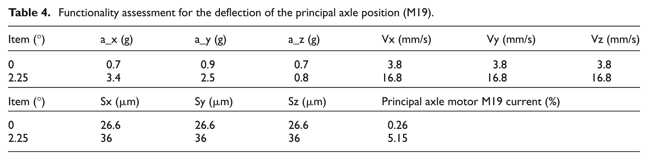
When the position of the principle axle is abnormal or experiences deflection, it will cause the drive key slot of the principal axle to be beaten inappropriately during tool change, as shown in Figure 3. This experiment performs an experiment for the deflection angles of 0° and 2.25°. The result of this functionality assessment is shown in Table 4.

Deflection of the principal axle position (M19).
Functionality assessment for the deflection of the principal axle position (M19).
Weight of the change arm with a tool
When performing an ATC, the change arm of the ATC takes the tool from storage with one side to perform the change with the tool that the principal axle is using. Therefore, when the change arm is carrying a heavier tool, deformation of the change arm or a shift in the angle at which the tool is held may occur, as shown in Figure 4. Therefore, this study performs an experiment with a tool of 0 kg (i.e. an empty tool) and a tool of 18.3 kg (i.e. a heavy tool). The result of this functionality assessment is shown in Table 5.
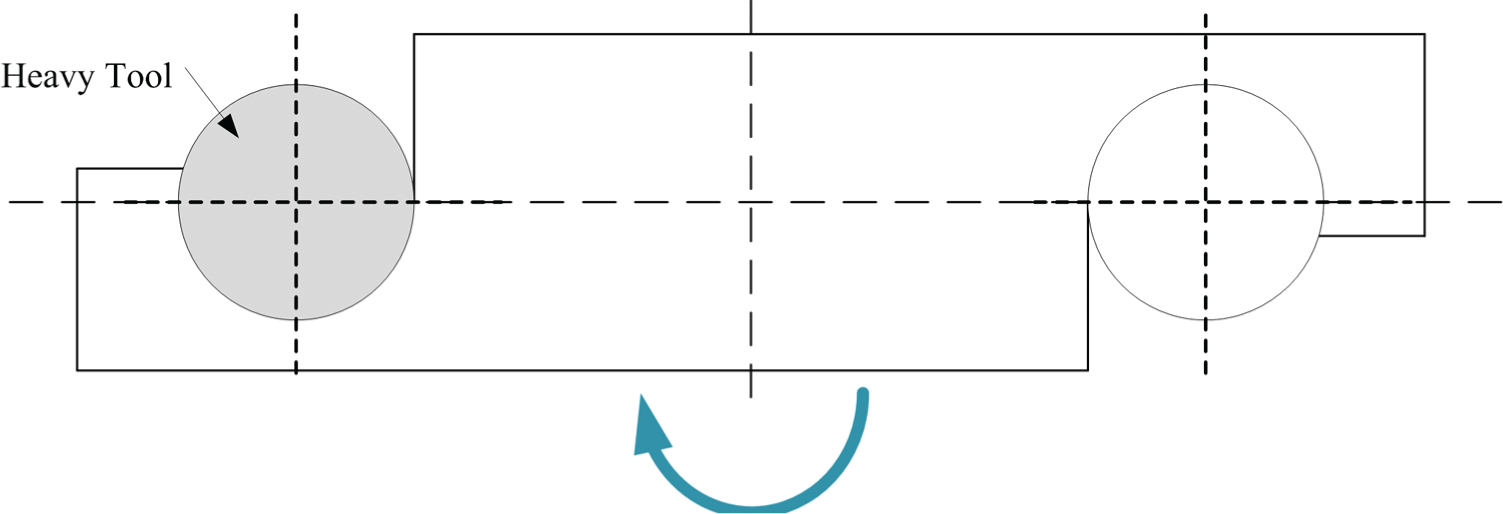
Weight of the change arm with a tool.
Functionality assessment for the change arm with the weight of the tool.

Shift in the tool change position
When performing the ATC, the change arm will take the tool from storage for the tool change when the principal axle is finished using the original tool. The long period of weight imbalance on both sides of the change arm will result in a deformation that causes a shift in the tool change position, as shown in Figure 5. Therefore, this experiment targets the radial and axial shifts, and the variables are shown in Table 6. The result of this functionality assessment is shown in Table 7.
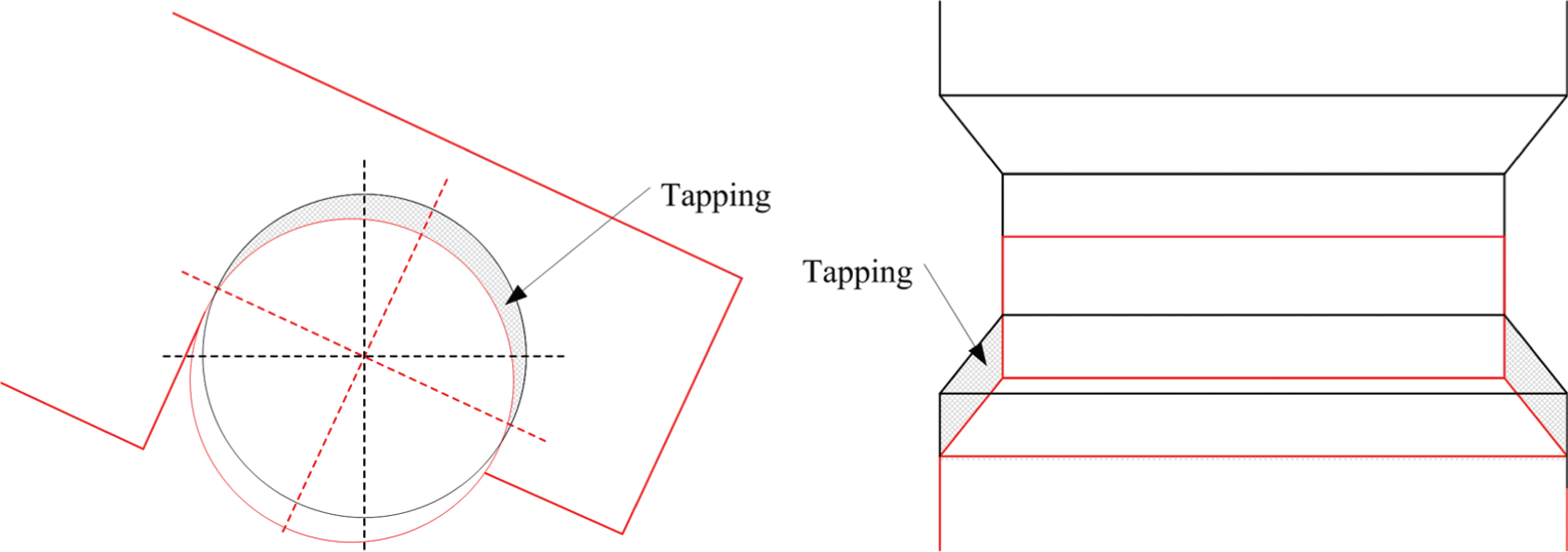
Shift in the tool change position.
Experimental variables for a shift in the tool change position.

Functionality assessment for a shift in the tool change position.

Abnormality in the principal axle holding tool
After the ATC system is completed, there will be some iron filings, oil stains, or other damages to the mechanical components that will lead to an abnormality in the principal axle holding tool after the automatic tool change is completed, as shown in Figure 6. Therefore, when the principal axle has completed the tool change, it will run at the highest speed to determine whether the held tool functions are normally based on the vibration values produced. This experiment has a total of three controlled factors to be tested.

Abnormality in the principal axle holding tool.
Effect of different rotational speeds
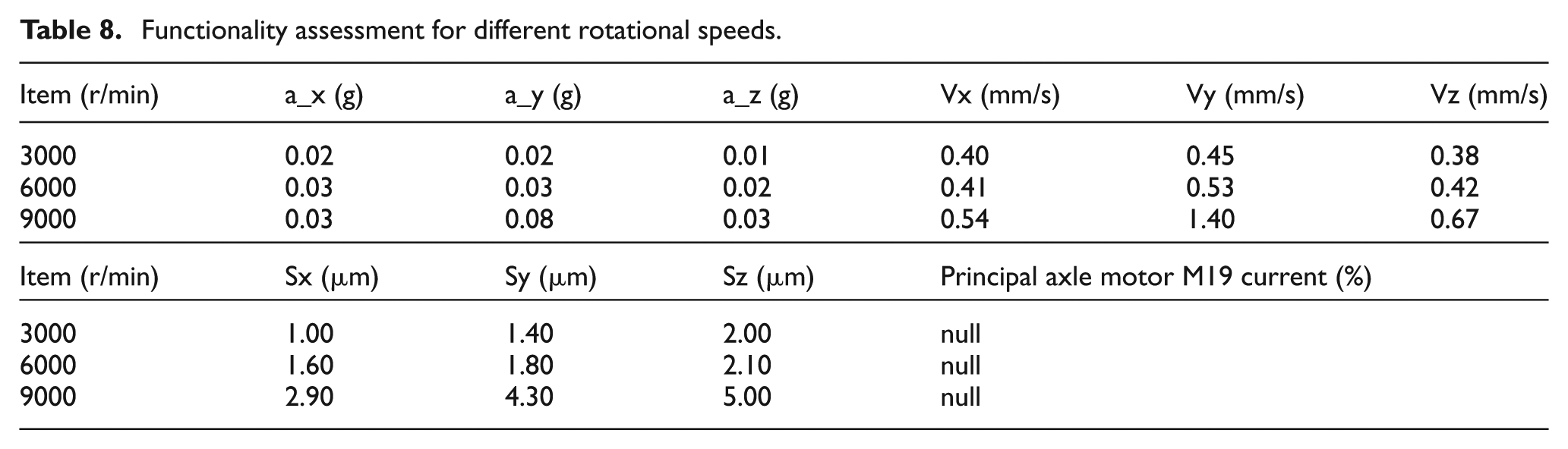
When the tool held is abnormal, the rotation of the principal axle will have an abnormal vibration. To test whether there is a difference between the vibrations produced at a high rotation speed and a low rotation speed, this experiment used three different rotational speeds to perform the experimentation. These rotational speeds are 3000, 6000, and 9000 r/min. The result of this functionality assessment is shown in Table 8.
Functionality assessment for different rotational speeds.
Effect of a change in the weight of a tool
To determine the difference in vibrations detected during an abnormal holding situation caused by the weight of the tool, this experiment uses tools of two different weights and performs the experimentation during rotation. The weight of the two tools used is 7 kg (i.e. a normal tool) and 12 kg (i.e. a heavy tool). The result of this functionality assessment is shown in Table 9.
Functionality assessment for a change in the weight of a tool.

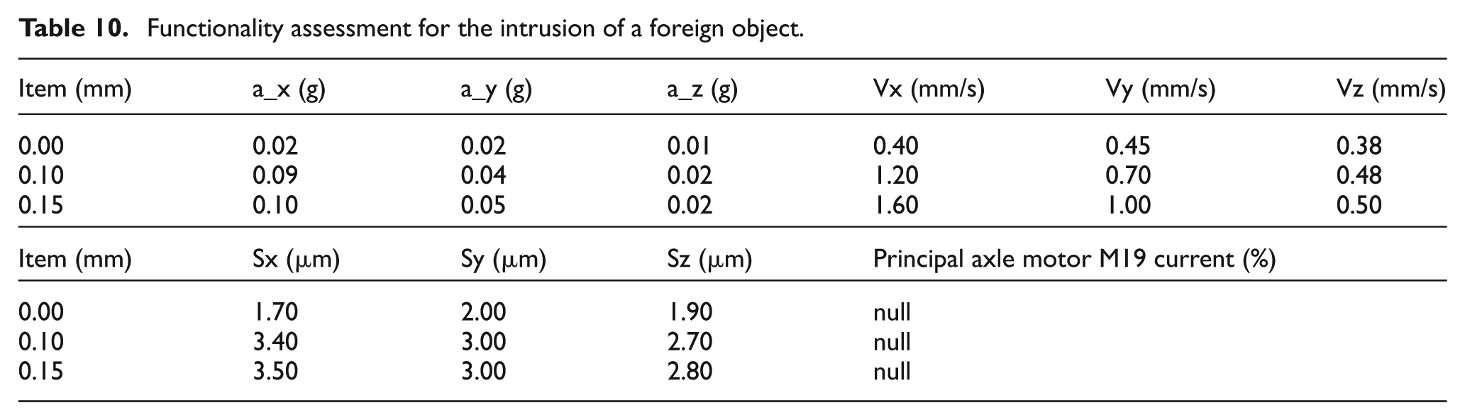
Inappropriate tool holding due to the intrusion of a foreign object
When a tool is sent to the principal axle for holding, there may be some filings or oil stains from the processing environment sticking or intruding into the tool holding area and may even enter the principal axle holding region. This leads to an angle of deflection in the tool held. Therefore, this experiment uses iron filings of three different thicknesses (i.e. 0, 0.1, and 0.15 mm) to perform a comparison. The result of this functionality assessment is shown in Table 10.
Functionality assessment for the intrusion of a foreign object.
Comparison of the vibration signal
This study developed a vibration sensor and signal retrieval card. To test whether the effect is similar to those available in the commercial market, we performed a comparison between the self-made vibration sensor and two vibration sensors available in the commercial market. Their specifications are shown in Table 11.
Specification of vibration sensors.

Experimentation on each vibration sensor in this experiment is performed using the same principal axle, as shown in Figure 7. The vibration diagram detected is shown in Figure 8. Figure 8(a) shows the self-made vibration sensor with an ADXL001-70 chip, Figure 8(b) is the sensor with the ADXL345 chip available in the market, and Figure 8(c) shows the NI vibration sensor available in the market. The experimental results show that the NI vibration sensor performs similarly to the self-made vibration sensor with only a small difference, and therefore, the self-made vibration sensor in this study can not only reduce costs significantly but also has an approximately 90% similarity in results to a high-precision vibration sensor available in the commercial market.

Vibration sensor experiment.

Values detected by the vibration sensors: (a) ADXL001-70, (b) ADXL345, and (c) NI 780989-01.
ATC performance assessment of experiment
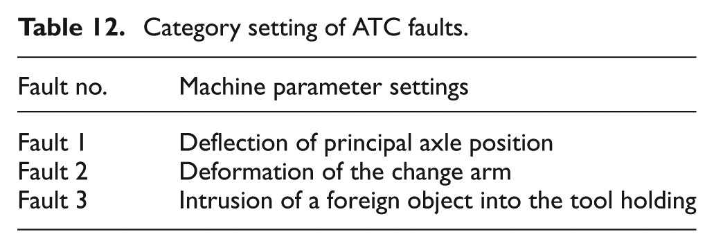
The accelerometer was disposed on the spindle of experiment, and the three sets of sensors, respectively, tested X, Y, and Z axes of the test object. The sensors were disposed in the relative positions of the spindle, as shown in Figure 9. A total of three channels were used for test in the experiment. First, the model training used 2400 signals in total of four states, followed by 2400 signals, a total of 12 sets, for performance assessment and fault diagnosis. The results would determine whether ATC is under normal operating condition, and which state of fault it is when it occurs. Table 12 shows the category setting of ATC performance status.

Sensor disposed in the relative positions of the spindle.
Category setting of ATC faults.
ATC performance assessment
Each test file has 200 test signals, while each channel has four test files. A total of three channels were used for performance assessment and fault analysis of ATC. The results of the performance assessment are shown in Table 13.
ATC for performance assessment report.

Accuracy = (Times correctly tested)/(Times tested).
ATC fault diagnosis
When the test signal showed fault in the report, fault diagnosis function would immediately be activated, and analyze and determine which state of fault it was based on the test signals in the occurrence of fault. Table 14 shows the results of fault diagnosis. Time spent on fault diagnosis by the system depended on the amount of test signals. In this experiment, real-time system diagnosis was approximately 0.51 s.
ATC of fault diagnosis report.

Accuracy = (Times correctly tested)/(Times tested).
Conclusion
The ATCMS constructed in this study has the comprehensive functions of signal retrieval, signal processing, and functionality assessment, and it is a combination of the Nyquist sampling theorem, the FFT, and a PCA. It is able to determine rapidly the immediate situation that occurs during tool change and may reduce the defect rate during processing, increase productive efficiency, and productive competitiveness. The analysis method and experiment results mentioned in this study may be summarized by the following points:
Comprehensive analysis of the ATC: a vibration sensor may perform an assessment and diagnosis suitable for the tool change functionality state.
Effective and accurate assessment of the performance of the ATC: this study uses discrimination and multivariable analysis to establish a threshold for the functionality assessment to determine rapidly and correctly the functionality of the tool change.
Self-made vibration sensor and signal retrieval card: this method allows the system to have a good adaptability and a high degree of cooperation. It may be applied to machines of any models and is not restricted to the subject in this study. However, the subject must have a repetitive working mode, such as a compound or rotary machine.
Footnotes
Academic Editor: Stephen D Prior
Declaration of Conflicting Interests
The author(s) declare no potential conflicts of interest with respect to the research, authorship, and/or publication of this article.
Funding
The author(s) disclosed receipt of the following financial support for the research, authorship, and/or publication of this article: The authors are grateful to the Ministry of Science and Technology for providing funding and technical support to this study through grant no. 103-2221-E-006-085. They are also grateful to Tongtai Machine & Tool Co., Ltd. for providing machine tool support. Because of their support, this study was able to be conducted smoothly.