
Abstract
The multi-joint snake robot is poised to become a crucial asset for investigation, surveillance, and attack in national defense and military applications. This paper addresses the trajectory tracking challenge of a multi-joint snake robot characterized by high redundancy and multiple degrees of freedom in the plane. We propose an adaptive trajectory tracking controller that accounts for non-holonomic constraints. This controller estimates unknown environmental parameters, effectively mitigating the negative impacts of uncertain and time-varying conditions during robot movement, thereby ensuring stability. A suitable Lyapunov function is identified to confirm the controller’s stability. The trajectory tracking performance of the robot is thoroughly analyzed through simulations and experiments, demonstrating the effectiveness of the proposed adaptive controller.
Introduction
A multi-joint snake robot is a bionic robot designed based on the structural characteristics and motion mechanism of biological snakes. This robot has the advantages of small volume, high flexibility, and various motion forms. It can move in narrow and unstructured terrain environments.1,2 The slender multi-joint snake robot can hide in grass and rock cracks, which greatly improves the application of the multi-joint snake robot in the military and national defense fields.3–5 Various complex environments will bring many restrictions and constraints to the task execution of the snake robot. Therefore, an adaptive control method suitable for the wheeled snake robot is considered to improve the robustness and motion ability of the robot. 6
To study the movement of biological snakes on land, Yamada 7 proposed the two-dimensional Serpenoid gait curve of the multi-joint snake robot and established the link model of series modular rotating joints. The link model in series will lead to the complex structure of the robot and the slow calculation velocity of the system. Moreover, the failure of any joint module may cause the paralysis of the whole snake. Rincon and Sotelo 8 established the kinematic model and dynamic model based on the peristaltic gait of the four-link snake robot. However, this four-link model has a simple structure and is seriously limited by the geographical environment. By studying the motion mechanism of biological snakes, Marvi et al. 9 found that the multi-joint snake robot could realize forward motion only when the tangential friction coefficient is greater than the normal friction coefficient, which greatly promoted the development of the motion control field of the robot. However, this cannot explain the principle of the robot lateral movement. Mohammadi et al. 10 designed a constraint function of the multi-joint snake robot based on head rotation angle and forward velocity and realized the path tracking control of the robot. However, this method has not been verified in the prototype experiment. Considering the virtual holonomic constraint function, a linear feedback control law for the multi-joint snake robot is designed, 11 which realizes the purpose of path tracking. However, their study did not consider the impact of non-holonomic constraints. The Serpentine curve for controlling the motion of the snake robot is proposed in Ma 12 and Ma et al. 13 Compared with the Serpenoid curve, the Serpentine curve has higher motion efficiency. However, they did not apply the Serpentine curve to robot trajectory tracking, which could not prove the trajectory tracking performance of the robot. Li et al.6,14 solved the fluid-structure coupling obstacle avoidance problem of the snake robot in fluid from the simulation perspective by using the IB-LBM method. This method can realize the underwater obstacle avoidance trajectory tracking of the robot. Nevertheless, it does not verify the stability of the robot trajectory tracking from a theoretical point of view. Chirikjian and Burdick 15 defines two helix direction angles from the geometric point of view, establishes the kinematics model of three-dimensional helical lateral movement of the multi-joint snake robot, and carries out simulation experiments on the model.
To realize the velocity tracking and head direction control of the snake robot, the parameters of gait function are designed by using the sliding mode control (SMC) method, 16 which ensures the robustness and stability of the robot when the friction coefficient changes. Hatton and Choset 17 analyzed the motion characteristics of the spiral side-shift of the multi-joint snake robot and improved the spiral curve motion function of the robot to the elliptic spiral curve motion function. Then, Yamada and Hirose 18 and Branyan et al. 19 put forward the three-dimensional conical spiral side-shift curve of the multi-joint snake robot. However, the robot needs control from the outside in the process of movement. Based on the Frenet Serret equation, Horigome et al. 20 established the three-dimensional link model of the arc-structure of the multi-joint snake robot and realized the smooth motion of the multi-joint snake robot in space. To consider the uncertainty and reduce the complexity of calculation, a time delay control (TDC) method for the snake robot based on virtual integrity constraints (VHCs) is proposed. 21 The designed two-layer delay control is applied to the output system to realize the dynamic stability of virtual holonomic constraints. In addition to motion modeling and gait control, the trajectory tracking of the snake robot needs accurate direction guidance and position control. To determine the motion direction using limited position information, Børhaug 22 proposed a line of sight (LOS) guidance method for the unmanned ship direction control. According to the mathematical and geometric relationship, this method converts the position error into the expected yaw angle of the unmanned ship and makes the motion position of the unmanned ship converge to the predetermined trajectory by adjusting the direction angle in real-time. After analyzing the model differences between the unmanned ship and snake robot, Yang et al. 23 uses the LOS method to guide the snake robot to move toward the virtual particle of the desired path, and realizes the trajectory tracking control of the robot prototype.
To reduce the restriction of unrestricted constraints on the multi-joint snake robot and improve the adaptive ability of the multi-joint snake robot to unknown environmental friction coefficient in the trajectory tracking process, an adaptive trajectory tracking controller of a multi-joint snake robot considering non-holonomic constraints is designed in this paper. The controller estimates the anisotropic friction coefficient in the system model through the motion state of the multi-joint snake robot, compensates the torque control input of the robot, reduces the negative impact of environmental friction on robot trajectory tracking, and enhances the robustness of the system. In addition, the robot can adjust the joint angle and joint angle velocity, reduce the overshoot phenomenon in the trajectory convergence process, improve the tracking efficiency of the robot, and ensure the asymptotic stability of the system.
The main contributions of this paper are as follows:
The proposed controller estimates the anisotropic friction coefficient of the system model through the robot motion state, uses the estimated value instead of the actual value to compensate the torque control input of the multi-joint snake robot, reduce the negative impact of the unknown ground environment on the robot, and enhance the robustness of the system.
The constant parameters in the Backstepping virtual control equation are selected by the adaptive control method, so that the controller can independently adjust the joint angle and joint angle velocity according to the convergence of the robot state, reduce the overshoot phenomenon in the trajectory convergence process, ensure the asymptotic stability of the system, and improve the trajectory tracking efficiency of the robot.
The rest of this paper is organized as follows: in Section 2, the mechanical model of a multi-joint snake robot is established. In Section 3, the control objectives for the joint angle, link angle, actuator torque, motion position and velocity of the robot are established. In Section 4, we design an adaptive trajectory tracking controller of the robot by the adaptive method and find a Lyapunov function, which proves the stability of the controller. In section 5, simulation and prototype experiments of the multi-joint snake robot are carried out to verify the effectiveness of the proposed controller. Section 6 draws a conclusion.
Modeling
Mechanical model
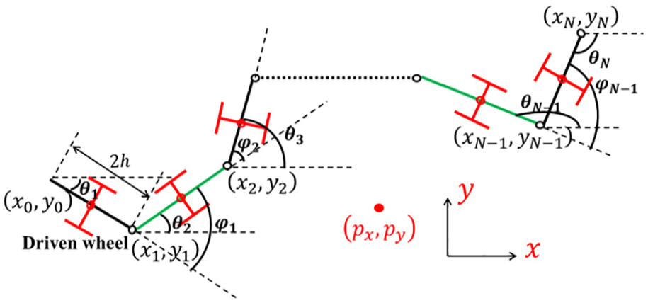
In this part, the mechanical model of the multi-joint snake robot with non-holonomic constraints is established.24–26 The prototype structure of the snake robot consists of several link modules, which are connected by active revolute joints. These active joints enable precise control of the robot’s movements in the XY plane, allowing it to perform complex motion patterns. The joint drives the link to swing alternately so that the body of the robot presents a S-shape, to obtain the forward power. To establish the mathematical model of the snake robot, we consider that the robot is composed of N links with a length of 2 h. There is a joint between the links, the joint steering gear controls the drive of the link, and there are auxiliary wheels in the middle of each link. In the dynamic model of the multi-joint snake robot, the width of joints and links are not considered temporarily. A simplified model of the robot dynamics is shown in Figure 1.
Dynamic model of the multi-joint snake robot.
The directional angle of the
A simplified model of the multi-joint snake robot with non-holonomic constraints is established as (1).10,11

where,
Coordinate transformation
In the snake robot dynamic model (1),

where

where
Design objectives
In this part, we will develop the control objectives of the adaptive trajectory tracking controller of the multi-joint snake robot with non-holonomic constraints.10,11
Objective 1. Gait control: An input-output feedback controller is designed to make the gait tracking error of the multi-joint snake robot stable.
Objective 2. Joint angle control: The desired joint angle motion function
Objective 3. Link angle control: The desired link angle motion function
Objective 4. Actuator torque vector control: This is the key to the design of the controller. We set the desired values of the ideal actuator torque vector
Objective 5. Motion position and velocity control: The desired position
When the gait control and direction control of the robot are designed, we need to design objectives 1–5 successively. Simultaneously, an appropriate Lyapunov function needs to be found to prove the stability of the system. When objective 1 is realized, the multi-joint snake robot can achieve forward motion in a winding gait. When objective 2 is realized, the link angle of the robot converges to the desired value, making the robot move toward the specified path direction. When objective 3 is realized, the joint angle converges to the desired value, so that the swinging amplitude of the robot joints can be realized in the form of winding. When objective 4 is realized, the actuator torque converges to the desired value, so that the joints of the robot can maintain a stable rotation velocity. When objective 5 is realized, the robot will move forward along the desired path. Meanwhile, the motion velocity of the robot follows the desired value, that is, the position error and the motion velocity error converge to zero.
Adaptive controller design
In this part, we mainly design the adaptive trajectory tracking controller of the multi-joint snake robot to realize the gait control and direction control of the robot. The controller can estimate the system model’s anisotropic friction coefficient and replace the actual value with the estimated value to compensate for the robot’s torque control input, reducing the negative impact of the unknown ground environment. Now we will realize the five control objectives proposed in Section 3.
Gait control
The forward motion of the robot is realized by controlling the swing amplitude and swing frequency of each joint of the multi-joint snake robot.
20
The motion function of the

where
Joint and link angle controllers
To make the multi-joint snake robot move toward the specified path direction, we set up an ideal joint angle motion function
The virtual feedback controller is set as

where

The joint angle error of the robot is set to (7).

where
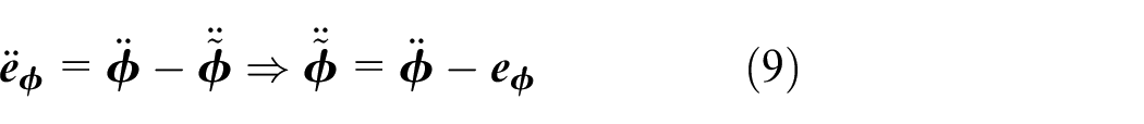
After differentiating the link angle error of the robot, equations (8) and (9) are obtained.

To make the multi-joint snake robot able to wind and swing, the desired link angle

The link angle error of the multi-joint snake robot is differentiated to get
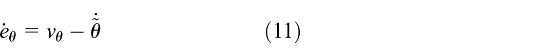
The angle velocity error of the robot is


Let

where
The joint offset compensation of the motion function of the multi-joint snake robot is designed as

where
To make the joints of the multi-joint snake robot maintain a stable rotation velocity, we set the ideal actuator torque vector
The torque vector error of the actuator is differentiated to obtain

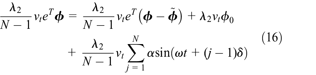
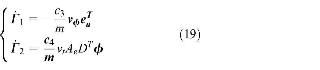
To make the adaptive trajectory tracking controller of the robot adapt to the environment, we design the control input function (10)–(18).

where
where
Stability analysis
Lyapunov candidate function

where
Lyapunov candidate function

Because,


So,

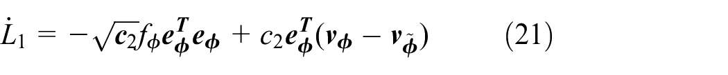
Lyapunov candidate function


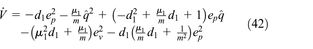
Combined with (21), (27), and (29), the Lyapunov function

As long as
Position and speed control
To control the motion position and velocity of the multi-joint snake robot on the desired path, we set up a desired position
The motion position and motion position error of the robot are differentiated to obtain (31) and (32).


The Lyapunov candidate function


And,

The Lyapunov candidate function

where

Moreover
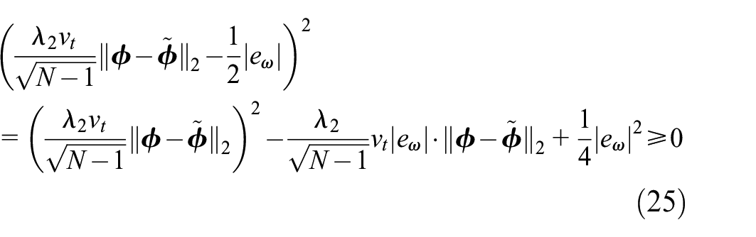
The Lyapunov candidate function


Combining the Lyapunov candidate function set above,

When

So
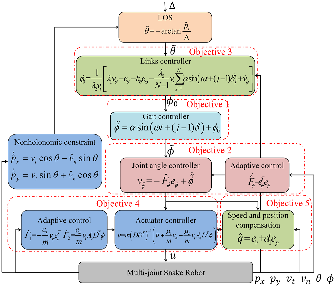
Trajectory tracking controller of the robot.
Simulations and experiments
In this section, we will carry out simulation experiments and prototype experiments to verify the effectiveness of the adaptive trajectory tracking controller of the multi-joint snake robot considering non-holonomic constraints.
Simulations
Following the shape of the multi-joint snake robot, the number of joints of the robot is set as
In addition, to demonstrate the performance of the proposed method, we compared it with traditional trajectory tracking controllers (PID) and adaptive central pattern generator (CPG) controllers
26
in simulations. The link angle and the desired link angle curve of the multi-joint snake robot under the proposed controller with non-holonomic constraints are analyzed, as shown in Figure 3. There is a big deviation between the link angle

The center of mass motion trajectory of the multi-joint snake like robot is shown in Figure 4. All three controllers can cause small-scale displacement of the robot’s center of mass motion trajectory within 10 s during the motion of a multi-joint snake robot, which is caused by small vibrations caused by frictional forces in the actual motion of the robot. In contrast, under the control of the proposed method, the trajectory of the robot’s center of mass gradually stabilizes after self-adjustment. The above results indicate that compared with other controllers, the proposed controller can more effectively reduce the offset of the robot centroid trajectory.

Centroid motion trajectory.
The joint angle error curve of the multi-joint snake robot is shown in Figure 5. Under the control of the three controllers, the joint angle error of the robot gradually converges and tends to be stable during the movement of the robot after 10 s. The motion velocity of the multi-joint snake robot is directly affected by the friction in different terrain environments. The motion velocity error of the robot under the control of the different controllers gradually converges and tends to be stable during the movement of the robot after 10 s. The above results show that the proposed controller can reduce the velocity error of the robot at the initial moment.

The torque control input of each joint of the multi-joint snake robot is shown in Figure 6. The control input changes obviously within 10 s, which can provide a faster starting velocity for the robot. After 10 s, the control input tends to be stable and presents a regular sinusoidal change, which is consistent with the winding motion characteristics of the snake robot.

Control input
The estimated values of viscous friction coefficients and control parameters of the multi-joint snake robot are shown in Figure 7.

Estimates
The variance and root mean square (RMS) of the trajectory tracking performance under the action of different controllers are shown in Figure 8. Because the variance and RMS can reflect the degree of numerical dispersion and the offset between variables and expected values, the smaller the variance and mean square deviation of trajectory tracking performance, the better the control ability of the controller. The figure shows that compared with the other controllers, the proposed controller effectively estimates the friction coefficient, reduces the robot link angle, joint angle error, and motion speed error, and improves the system control accuracy.
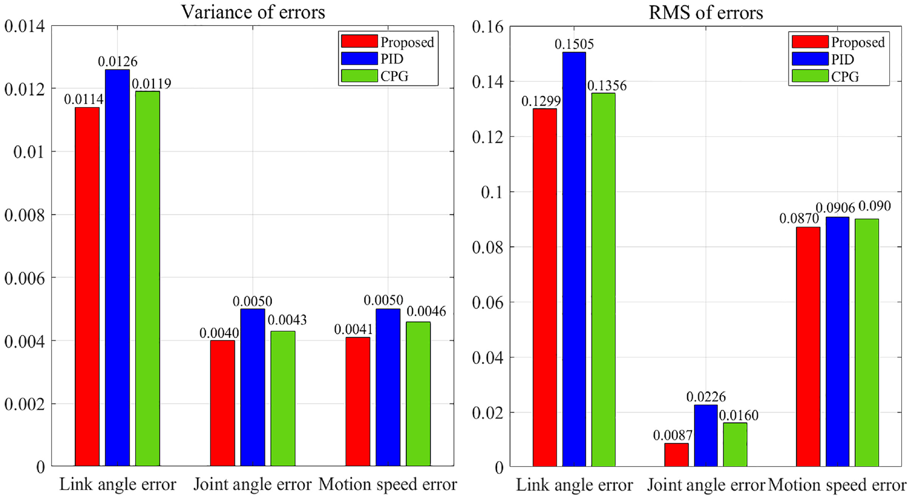
RMS error comparison of different controllers.
Experiments
In this part, we carry out a prototype experiment on the multi-joint snake robot with non-holonomic constraints to verify the stability of the adaptive trajectory tracking controller, as shown in Figures 9–11. The planar motion capture system is used to measure the relative position coordinates of robots. The system is fixed above the experimental area and obtains the position information of the robot relative to the preset coordinate system on the ground through video images. The coordinate system is set on the plane of the experimental site and within the field of view of the camera system to ensure accurate capture of the robot’s motion trajectory. For the convenience of design, the multi-joint snake robot adopts

Joints and links of the multi-joint snake robot.

Motion capture system.

Prototype experiment of the multi-joint snake robot.
The robot is manufactured using 3D printing technology and moves forward by utilizing the friction between itself and the ground. A modular structure is adopted between the joints, with the main control module responsible for coordinating the robot’s movements. Each joint is equipped with angle sensors that record and provide feedback on joint rotation while calculating the robot’s motion direction angle in real time. The Bluetooth wireless transceiver module receives instructions from the upper computer and provides feedback on the robot’s status, while the joint modules execute the commands issued by the upper computer. Additionally, each link of the robot is equipped with an auxiliary wheel below it, which is designed to generate asymmetric friction in the normal and tangential directions, allowing the snake like robot to effectively move forward in a two-dimensional plane. They only provide auxiliary motion and do not directly provide power. Each joint has two actuators, with each motor controlling rotation in one direction. The control system of the multi-joint snake robot uses a bus to facilitate communication between the modules. To ensure fair comparisons, the same control parameters are used for components with identical structures, while original parameters are set according to relevant literature for different parts. Furthermore, to minimize the impact of randomness on the results, each algorithm is subjected to multiple experiments in the same hardware and software environment, including the operating system, computer processor, memory, hard disk capacity, and other factors.
To analyze the performance of the multi-joint snake robot in motion, we extract the performance indexes of the first joint and the sixth joint on the straight path of the robot. The robot will adjust the relationship between its actual position and the ideal position during the movement of the robot before 100 cm. When the robot moves to 100 cm, the actual position of the robot tracks the desired position almost perfectly, as shown in Figure 12. Meanwhile, the robot will adjust the relationship between the actual link angle and the desired link angle during the movement of the robot before 150 cm. When the robot moves to 150 cm, the actual link angle of the robot tracks the desired link angle almost perfectly. The multi-joint snake robot will have a small amplitude of oscillation in the initial period of movement, which is the self-adjustment process of the robot. Meanwhile, the motion position and link angle of the robot lag slightly compared with the ideal value, because the movement process of the robot will be affected by environmental factors. When the position and link angle of the robot are adjusted to reasonable values, the robot tracks the desired motion position and desired link angle under the control of the adaptive trajectory tracking controller.

The position and link angle of the robot.
Conclusions
This paper presents an adaptive trajectory tracking controller for a multi-joint snake robot that effectively addresses non-holonomic constraints, achieving stable tracking in varying friction environments. The proposed controller demonstrates significant improvements in accuracy and robustness. However, its design is currently limited to two-dimensional environments and relies on accurate parameter estimation. Future work will focus on extending the controller’s application to three-dimensional scenarios and enhancing its adaptability under dynamic conditions.
Footnotes
Appendix
Handling Editor: Aarthy Esakkiappan
Declaration of conflicting interests
The author(s) declared no potential conflicts of interest with respect to the research, authorship, and/or publication of this article.
Funding
The author(s) disclosed receipt of the following financial support for the research, authorship, and/or publication of this article: The authors appreciate the support from National Natural Science Foundation of China with the Research Project on Human-Machine Collaborative Decision-Making (No.72192822) and Fujian Provincial Natural Science Foundation (2024J01278).