
Abstract
For large-span cable-stayed bridges, cross-ties and dampers can work together for vibration mitigation of cables. Common analyses pay attention to the effectiveness of cross-ties and external dampers on two adjacent cables, fewer studies are available on the combined effect in multiple-cable networks. Investigating the optimization of multi-cable system parameters is a crucial problem for effective vibration mitigation. This paper proposes a model of the multi-cable hybrid network (MCHN) system. The corresponding characteristic equation is derived, and the analytical solutions for modal frequency and damping ratio are calculated. Furthermore, the results are verified through comparison with finite element and experimental results of a three-cable hybrid system. An analysis of the in-plane natural vibration characteristics of MCHN systems is presented, utilizing a numerical example of a three-cable MCHN system. Key parameters such as cable length differences, mass-tension ratio, cross-tie stiffness, damper number, damper location, and damping coefficient are considered to investigate their influence on the damping. A multi-modal optimization criterion (MANDR) based on maximizing the average of damping ratio is proposed by normalization of the system modes. When dampers are selected according to the optimization criterion of MANDR and installed in appropriate locations, the damping capacity can be better utilized.
Keywords
Introduction
With the development of bridge construction, the application of cables is increasing rapidly. The stay cables of the cable-stayed bridge and the long hangers of the suspension bridge have the characteristics of light weight, low inherent damping, and large lateral flexibility. Under external loads and parameter excitation, the stay cables are prone to significant vibrations, which can induce fatigue and damage to corrosion protection measures, ultimately resulting in reduced lifespan of the cables and their connecting components.1,2 The common methods to reduce the vibration of the cables are aerodynamic measures, installing dampers and cross-ties.3–5 Among them, the formation of hybrid system is a promising method in recent years, by connecting cables with cross-ties and installing dampers on the cable end.
Researchers have carried out relevant research on the vibration characteristics of cables with dampers and cross-ties. Pacheco et al., 6 Krenk, 7 Chen et al.8,9 have conducted research on utilizing dampers to control cable vibration and compared the effectiveness of different types of dampers. Yamaguchi and Nagahawatta, 10 Caracoglia and Jones,11,12 Ahmad et al.13–15 have studied simplified models of cable networks formed by cross-ties connecting multiple cables. Chen et al., 16 Sun et al.,17,18 Di et al., 19 and Chen et al. 20 have analyzed the effects of cable bending stiffness, sag, and pre-tension of cross-ties in simplified models of cable networks.
Since the cross-ties are usually unable to dissipate energy directly, and the installation location of the damper is usually very close to the anchorage end of the cable, its performance is limited by the installation location. Caracoglia et al.21,22 proposed combining cross-ties and dampers to form a hybrid system for vibration control. It was found that setting a damper to the cable net system with cross-ties can improve the damping of low modes. Zhou et al.23–26 conducted an analysis of the damping and frequency characteristics of single cable and two cable system equipped with dampers and cross-ties, and found that the vibration control effect of hybrid system is sensitive to the relevant parameters of cross-ties and dampers. Ahmad et al.27–30 proposed a general method to establish the analytical model of two-cable hybrid system, and studied the influence of the main system parameters on the two-cable hybrid system. Furthermore, the influence of the stiffness and installation location of the cross-tie on the damper was discussed, and the combined effect of a passive viscous damper and an HDR damper in a two-cable hybrid network was explored. Di et al. 31 derived an improved model of the two-cable hybrid system by considering the sag of the cable and the pre-tension of the cross-tie, and discussed the influence of the pre-tension of the cross-tie on the system.
Although researchers have recognized that the hybrid vibration control systems are more effective, extant research on the hybrid system mostly focuses on two-cable network. For the MCHN systems, particularly those incorporating multiple dampers and cross-ties, further research is still required. Di et al.32,33 have conducted experimental studies on the three-cable hybrid system and explored the optimization of the multi-cable hybrid network (MCHN) system using a multi-objective genetic algorithm. Chen et al. 34 have proposed a component mode synthesis method for reduced-order modeling of cable networks in cable-stayed bridges, while Su et al. 35 have studied generalized methods for in-plane free vibration of cable network attached with multiple rigid cross-ties. These studies, which address diverse aspects of cable networks, have collectively contributed to advancing our understanding of MCHN systems. Nevertheless, establishing an effective analytical model for MCHN systems with multiple dampers and cross-ties remains a necessary and challenging task.
Currently, design objectives for the MCHN system optimization is still unclear, and the establishment of a more effective numerical model for dynamic analysis is necessary. The application of MCHN systems for controlling cable structure vibration has considerable potential. As cables multiply and the introduction of dampers, more related parameters are involved, and the characteristic equations of the cable network system are more complex.
This paper proposes an analytical model for the MCHN system, focusing on the study of the in-plane natural vibration characteristics of MCHN system. The complex characteristic equation of the MCHN system is derived through theoretical derivations, and its accuracy was confirmed through experiments and finite element analyses. This study further investigates the inherent vibration characteristics of the MCHN system and the interaction between dampers and cross-ties. The vibration control effects of key parameters are analyzed, such as cable length differences, mass-tension ratio, cross-tie stiffness, damper number, damper location, and damping coefficient, and a theoretical framework is provided for the optimized design of the MCHN system.
Solution of vibration equation of the MCHN system
Vibration equation
A MCHN system model is established, as shown in Figure 1, which is composed of unequal lengths parallel cables with independent anchorage. The cables are designated according to their lengths, with the length of the longest cable denoted as L1 and labeled as Cable 1. The length relationship among the cables is expressed as L1 > L2 > … >Ln. The n-th cable possesses a tensile force of Tn and a mass per unit length of mn. The cables are connected by lightweight cross-ties with certain stiffnesses, and dampers are installed on each cable.
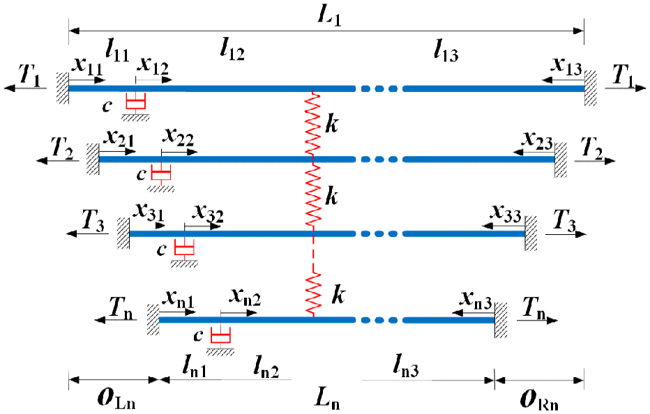
MCHN system model.
The damping coefficient of the damper is c, and the cross-ties stiffness is k. The cross-ties and dampers divide n cables into 3n cable segments, with each length be l11, l12, l13, …, ln1, ln2, ln3. OLn and ORn represent the offsets of the n-th cable from the anchoring end of the cable 1.
For cable segments l13, l23, …, ln3, the axial coordinates are established with the right ends as the origins. For other cable segments, the axial coordinates are established with the left ends as the origins.
Assuming that each segment of the cable experiences equal forces and has a uniform mass per unit length, the differential equation describing the transverse vibration of a single cable segment under tension can be written as

where v(x, t) represents the lateral displacement of the cable; x corresponds to the coordinate along the cable axis; t denotes the vibration time; T indicates the cable tension; m is the mass per unit length of the cable.
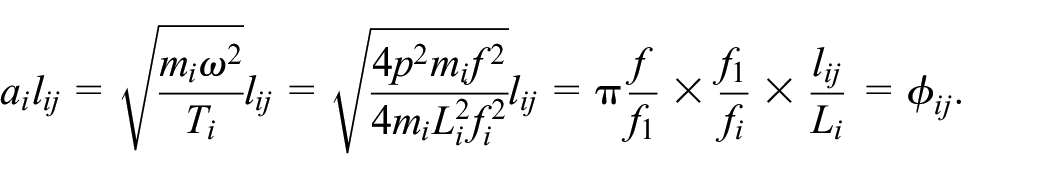
Equation (1) can be solved using the method of separation of variables. Let the displacement form of the free vibration of the j-th segment of the i-th cable be written as

where
Substitute the equation (2) into the equation (1) and simplify the expression, resulting in equation (3).

The equation (3) represents a second-order homogeneous linear ordinary differential equation. For the MCHN system, since cable segments are coupled, the vibration complex frequencies of each segment can be approximately considered equal, denoted by

where
By substituting the equation (4) into the equation (2), the vibration form of each cable segment is expressed as equation (5), and the corresponding vibration mode equation is obtained as equation (6).


where i represents the serial number of the cables, j denotes the segment number.
The equation (6) gives 6n undetermined coefficients. The solutions can be derived by considering the boundary conditions, continuity criteria, and vertical force balance requirements.
Boundary condition
Due to the consolidation of both ends of the cables, the displacement at each cable end is zero. Equation (7) can be derived as

Substituting equation (7) into the equation (6) yields that
Continuity requirements
It is evident that the displacements at the junctions of adjacent segments are equal, given as


The displacement conditions of adjacent cables connected by the same cross-tie can be formulated into equation (10).

where r ranges from 1 to n−1.
Vertical force balance requirements
Under the condition of vertical force balance, the vertical force at the coupling point should satisfy the balance requirement, resulting in the following equations


Solution of frequency and damping ratio
For the MCHN systems,
In order to simplify the complex characteristic equation, all parameters are standardized to non-dimensional forms.
Non-dimensional parameters are defined as follows. The non-dimensional damping coefficient

The equations (8)–(12) can be simplified and rearranged to obtain equations (13)–(17).


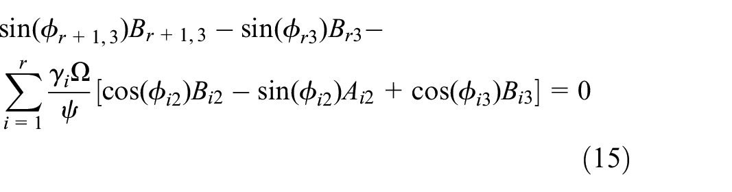


The above 4n equations can be written in matrix form

where

If equation (18) has a solution, then the determinant of the coefficient matrix is zero. That is, the system has a complex characteristic equation

With only one unknown variable f present in equation (19), it can be solved simply through programming with mathematical software like Wolfram Mathematica to ascertain the natural frequency and damping ratios for each mode of damped vibration.
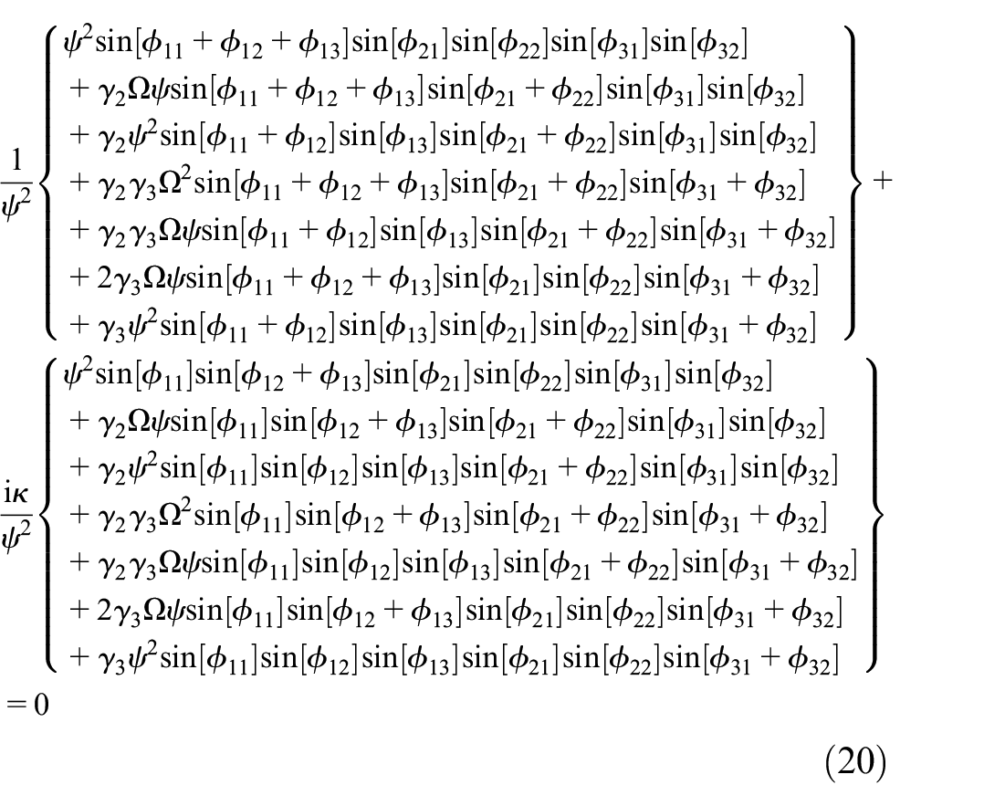
If the model changes, such as using more cross-ties or adopting different types of dampers, the equation (19) can be adjusted following the derivation process outlined above. For example, in the case of a three-cable hybrid network system with a single damper installed on cable 1, a modified equation similar to the equation (18), expressed as
Model experiment and simulation analysis of the MCHN system
To verify the accuracy of the theoretical formula, a simplified model of a three-cable MCHN system with a single damper is established. Subsequently, the natural frequency and damping ratio are obtained through Model experiments and finite element simulation analysis, and the results are compared to those obtained from the theoretical formula.
Model experiment
A Model experiment was conducted to validate the theoretical formula. Figure 2 illustrates some of the equipment utilized at the experiment site of the three-cable MCHN system. The system parameters are as follows: the elastic modulus of the cable E = 1.95 × 10¹¹ Pa, the cross-sectional area A = 1.39 × 10⁻⁴ m2, and the cross-sectional moment of inertia I = 1.536 × 10⁻⁹ m4. L1 = L2 = L3 = 3.37 m, T1 = 11 kN, T2 = 15.5 kN, T3 = 20 kN, m1 = m2 = m3 = 1.12 kg/m, c = 25 N s/m, k = 107 N/m. The cross-tie is located at a distance of L1/4 = 0.84 m from the left cable end, and the damper is 0.6 m away from the right cable end.

Equipments used in the experiments: (a) rigid cable clamp (k = 107 N/m), (b) viscous damper, and (c) pressure transducer.
A plurality of acceleration sensors were installed on the upper surfaces of the three cables and connected to the dynamic strain tester. The self-made liquid damper served as the viscous damper at the cable end. The parameters of the computer-side data acquisition system were adjusted, including a sampling frequency of 2000 Hz and sampling time of 30 s.
After data acquisition, a Fast Fourier Transform (FFT) was applied to the acceleration response signals of each cable, and the vibration amplitude spectra of the three cables were obtained respectively, as shown in Figure 3.
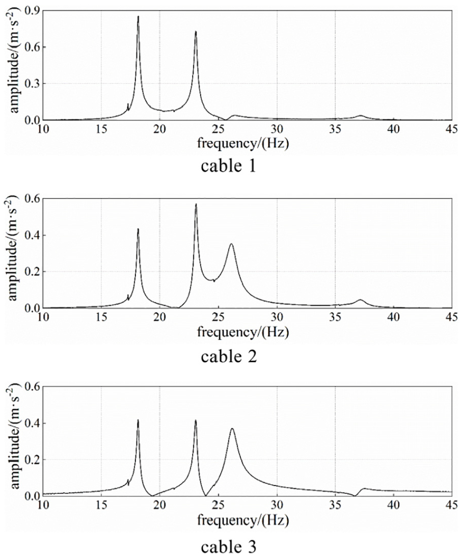
Amplitude spectrum of the three-cable MCHN system.
Simulation verification
Based on the three-cable MCHN system model of the experimental setup, the finite element software ANSYS was utilized for numerical simulation. Link180 and Beam188 elements were individually employed to simulate the cables. The Combine 14 elements, characterized by predefined stiffness and damping coefficients, were utilized to simulate the cross-ties and the damper, respectively. Tension was applied to each cable in the form of pre-tension, and the coupling of freedom degrees was realized at the nodes where the cross-tie and damper were interconnected with the cables. A comparative analysis was conducted among the analytical solution from the theoretical formula, the results from the finite element method, and the experimental findings, as detailed in Table 1.
Comparison of measured and calculated natural frequencies.

NDI and DI represent the status of non-damper-installed and damper-installed, respectively.
The natural frequencies of each mode obtained by various methods in Table 1 are quite close to each other. The measured natural frequency values are between the Beam188 simulation results and the theoretical results, and closer to the former. The main reason is that when the Beam188 element is utilized to simulate cables, the bending stiffness (EI) of those cables has been taken into account, based on the cable net parameters that were previously mentioned, and it has a significant impact on the natural frequency when the experimental cable length is 3.37 m. In engineering practice, the bending stiffness of the long cable has less impact on its natural frequency. 17
For a MCHN system with cables of equal lengths, if the tension and linear density are consistent, the measured natural frequencies of each cables are identical. Before and after the installation of the damper, the measured natural frequency changes. While due to the small damping coefficient, the maximum rate of change is 3%. This change is consistent with both theoretical results and predictions by finite element method.
By the JMTEST dynamic signal test and analysis software Version 8.5, the band-pass filtering function is utilized to isolate the first-order mode signal. Given that the first-order mode frequency remains at 18.19 Hz, the band-pass filter is configured with a lower limit of 17.19 Hz and an upper limit of 19.19 Hz. From the acceleration time history curve, 30 cycles of stable free attenuation are identified and used to calculate the first-order modal damping ratio ξ1 by the logarithmic decrement method. The measured first-order modal damping ratio is presented in Table 2.
Comparison of measured and calculated first order mode damping ratio.

The calculated first-order modal damping ratio ranges from 0.38% to 0.40%, which is smaller than the measured values of 0.58% to 0.62%. In addition to measurement and calculation errors inherent in the logarithmic attenuation method, the key factor is assumptions made in theoretical analysis and finite element modeling. Some important damping factors are neglected, such as cable damping, cross-tie damping, and frictional damping at the cable-cross-tie interfaces. As a result, the calculated first-order modal damping ratio only reflects the damping effect of the viscous damper, leading to a value that is lower than the actual measurements.
If no damper is installed, the calculated damping ratio is 0.24%, which further illustrates this point. The experimental results indicate that the installation of viscous dampers can significantly enhance the system damping ratio. This implies that the establishment of a MCHN system is beneficial for controlling cable vibrations.
Numerical example
To establish the theoretical basis for the optimization method of MCHN systems, the complex characteristic equation and the finite element method are utilized to analyze the three-cable MCHN system. Three typical stay cables from a cable-stayed bridge are selected, with three dampers, as shown in Figure 4. The lengths of the three cables are respectively L1, L2, and L3. Specifically, the cable length difference ΔL between adjacent cables is defined as 0.1L1, implying that L2 = 0.9L1 and L3 = 0.8L1. The offset of the left and right anchorage ends of the ith cable OLi = O
Ri
= (L1—Li)/2, the frequency ratio

Model of three-cable MCHN system.
The cross-ties are located at the midpoint of the cables. The non-dimensional cross-tie stiffness parameter Ψ ranges from 0.3 to 300. To prevent over-damping in the system, the damper adopts a smaller non-dimensional damping coefficient κ = 1. The non-dimensional location parameter of the damper is εi1 = 5%.
The analytical values of the first 10 natural frequencies of the system under different cross-tie stiffnesses were derived through theoretical formulations and subsequently rendered non-dimensional. The non-dimensional frequencies and damping ratios are presented in Table 3, while the first 10 mode shapes are illustrated in Figure 5, Ψ denotes the non-dimensional stiffness of the cross-tie with dampers installed, and Ψ’ refers to the stiffness with no damper.
The non-dimensional frequencies and damping ratio of first 10 modes.

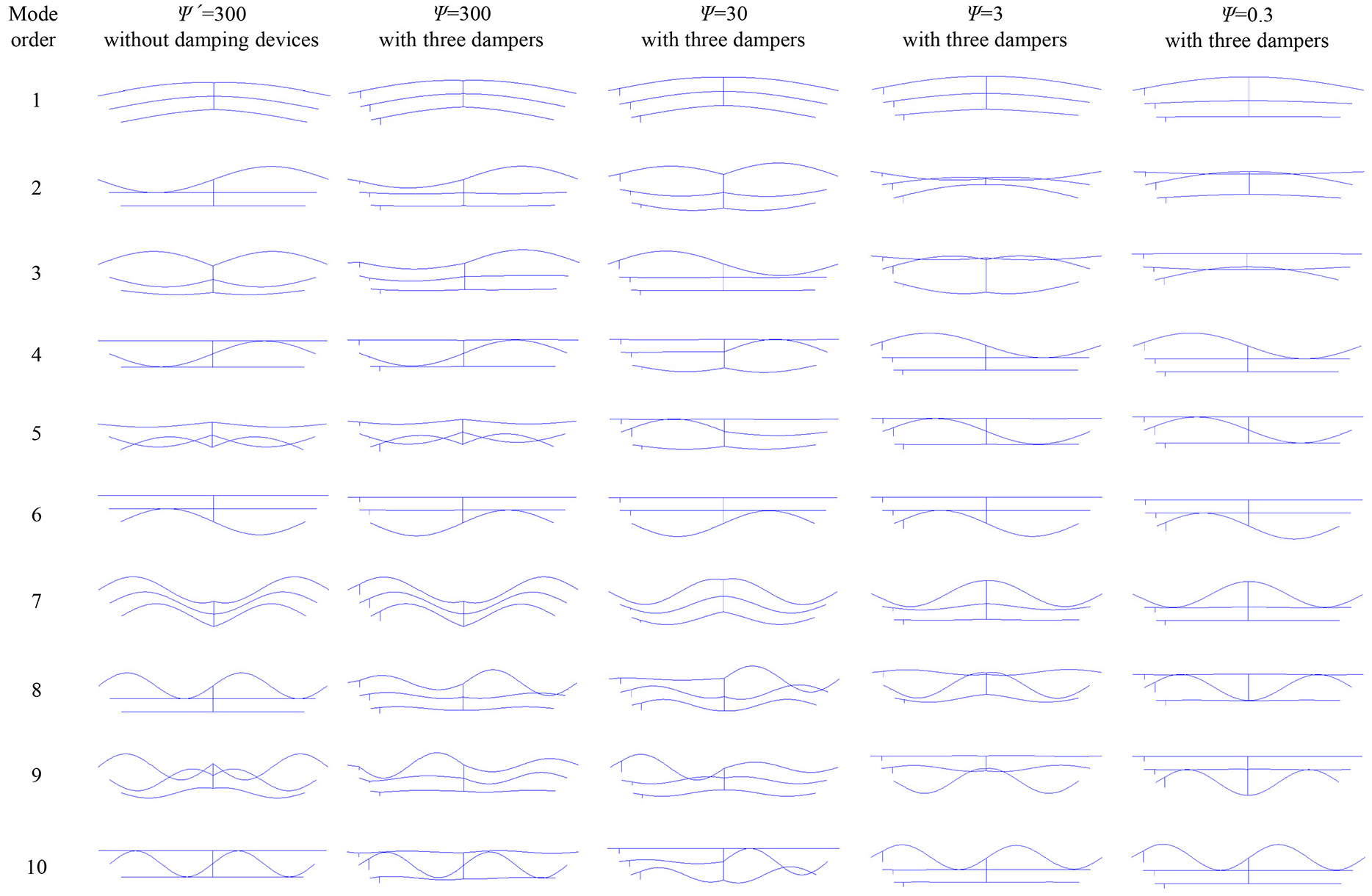
The first 10 mode shape diagrams of the system with different cross-tie stiffnesses.
As shown in Figure 5 and Table 3, if the three-cable system is equipped with multiple dampers, the damping ratio of each mode is non-zero, suggesting that introduction of multiple dampers is beneficial. For the MCHN system, the individual order frequencies increase in comparison to cables without dampers, and certain vibration mode shapes also exhibit differences.
The change of the cross-tie stiffnesses affect the magnitude of the damping ratio. The vibration mode shapes vary for each mode at different cross-tie stiffnesses, thereby resulting in unequal degrees of benefit. Moreover, the optimal cross-tie stiffness for achieving the maximum damping ratio varies across different modes.
As shown in Figure 5, the first 10 vibration modes can be categorized into three types: global vibration, multi-cable local vibration, and single-cable vibration. With the employment of more flexible cross-ties, the integrity of the vibration is poor, and the vibration modes are primarily single cable vibrations. When the non-dimensional stiffnesses of the cross-ties exceed 30, the system primarily exhibit multi-cable local vibration or global vibration, although there are still a few cases of single-cable vibrations.
The in-plane stiffness of the system increases with the cross-tie stiffnesses, thereby the integrity of the vibration is strengthened. Meanwhile, the first-order and seventh-order modes gradually transform from single-cable vibration to global vibration. In the process of transformation, the natural frequency gradually increases, the damping ratios remain similar across different cross-tie stiffnesses.
In the case of single-cable vibration, such as the sixth mode, if there is no damper on the cable, the natural frequency remains unchanged regardless of variations of cross-tie stiffnesses. However, upon the installation of dampers, a slight decrease in the natural frequency is observed as the cross-tie stiffnesses increase, accompanied by a gradual augmentation in the damping ratio. Similar trends are observed in other modes that involve single-cable vibration alone.
When the multi-cable local vibration occurs, if a cable segment equipped with a damper exhibits a significant local vibration, the system attains a high damping ratio. For instance, at Ψ = 30, the fifth modes exhibit local vibration on the segment with a damper of cable 2, while the ninth mode does so on the segment with a damper of cable 1, resulting in significant increase of the corresponding damping ratios.
Conversely, when the vibration amplitude is large in segments away from the damper and small in those with it, the damping ratio of the system is significantly reduced, such as when Ψ = 30 in the fourth, eighth, and tenth modes. This can be observed in the fourth, eighth, and tenth modes at Ψ = 30.
The magnitude of the damping ratio of the system is closely associated with the mode shape. If the vibration amplitude of a cable segment equipped with a damper is large, the damping ratio increases significantly. Furthermore, as each cable is equipped with a damper, the vibration modes of each order are influenced by dampers to varying degrees. Increasing damper number does not significantly alter the system natural frequency, while it significantly increases the damping ratio. Therefore, setting dampers on each cable can enhance the damping, provided that the integrity of the system mode is maintained. Deploying multiple dampers is advantageous for the vibration control of the multiple-cable system.
Parametric study on damping
This study focuses on investigating the influence of key factors on the damping ratio of a MCHN system. These factors include the number of dampers, damper location, damping coefficient, cable length difference, mass-tension ratio, and cross-tie stiffness.
The number of dampers
When a hybrid system is only equipped with a single damper, the damping effect on the system can be negligible if the amplitude of the damper cable segment in a particular mode is very small. To investigate the impact of the damper number on the vibration control of the MCHN system, this study examines a three-cable MCHN system equipped with one, two, and three dampers.
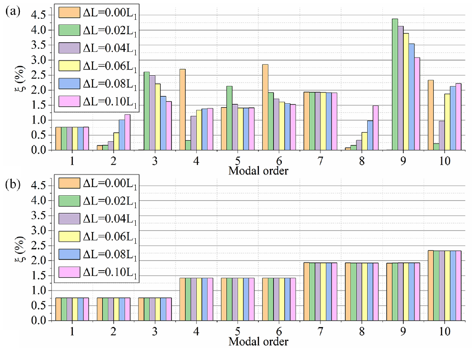
Specifically, a single damper is installed on cable 1, while two dampers configuration involves dampers on both cables 1 and 2. All other parameters remain unchanged. With different damper number and cross-tie stiffness, the damping ratios of first 10 order modes are shown in Figure 6.

The first 10 modal damping ratios: (a) Ψ = 300, (b) Ψ = 30, (c) Ψ = 3, and (c) Ψ = 0.3.
As shown in Figure 6, the damping ratio correlates with both the damper number and cross-tie stiffness. For each defined condition of the cross-ties stiffness, systems equipped with either a single damper or two dampers exhibits the specific modes with zero damping ratio. In these specific modes, there is no vibration in the cable segments with dampers. Conversely, the system with three dampers has a nonzero modal damping ratio for all of its modes.
When utilizing cross-ties with greater flexibility, the vibration integrity of the MCHN system is compromised, and most modes are characterized by single-cable vibration. If dampers are not installed on the vibrating cable, the damping ratios of those modes are zero. Furthermore, the number of dampers placed on other cables does not affect the damping ratios of these modes. For modes involving multi-cable local vibration, the greater the number of vibrating cables with dampers, the higher the modal damping ratio.
In the case of more rigid cross-ties, modes of global vibration or multi-cable local vibration often occur. If a cable segment with a damper exhibits vibration, the damper contributes to the damping ratio of the system, with the level of contribution related to the corresponding mode shape. The greater the amplitude of the cable segment where the damper is located, the greater the contribution of that damper to the damping ratio of those modes. For modes of multi-cable local vibration and global vibration, the more dampers, the greater the damping ratio.
With the increasing of cross-tie stiffness, the first-order mode changes from the single-cable vibration of cable 1 to global vibration. The MCHN system equipped with dampers on all cables does not exhibit a decrease in the first-order damping ratio as the enhancement of vibration integrity, whereas the first-order damping ratio of the other two MCHN systems gradually decreases.
In summary, the installation of multi-dampers can significantly improve the damping of the global vibration or multi-cable local vibration modes, which is beneficial to the vibration control of the MCHN system.
Damper location
To investigate the impact of the damper location on the system damping ratio, the cross-tie is set at the midpoint of the cable, the non-dimensional location parameters of dampers, εi1, range from 1% to 11%. Three working cases were established for analysis. In Case 1, the damper location changes simultaneously from the cable end to its midpoint, that is, the non-dimensional location parameters of each damper are equal. The relationships between the damping ratio of the first 10 modes and the damper location for Ψ = 300 and Ψ = 0.3 are presented in Figure 7(a) and (b), respectively.

The damping ratio for the first 10 modes under different damper locations: (a) Ψ = 300, εi1 = 1%–11%, (b) Ψ = 0.3, εi1 = 1%–11%, (c) Ψ = 300, ε11 = 1%–11%, and (d) Ψ = 300, ε31 = 1%–11%.
In Case 2, the damper location on cable 3 is maintained at ε31 = 5%, while the damper location on cable 1 varies from ε11 = 1% to 11%. In Case 3, the damper location on cable 1 is fixed at ε11 = 5%, and the damper location on cable 3 varies from ε31 = 1% to 11%. In both cases, the dampers on cable 2 are located on the straight line connecting the damper locations of cable 1 and cable 3, with cross-tie stiffnesses of Ψ = 300. The representative damper location parameter for Case 2 is ε11, which corresponds to the damper installed on Cable 1. The corresponding parameter for Case 3 is ε31, which represents the damper installed on Cable 3. The relationships between the damping ratios of the first 10 modes and the damper locations for Case 2 and Case 3 are shown in Figure 7(c) and (d) respectively.
As shown in Figure 7(a) and (b), the influence of the damper location on the damping ratio varies with different cross-tie stiffnesses.
When flexible cross-ties are used, the system is dominated by single-cable vibration. For the mode of single-cable vibration, variations in the system damping ratio occur in response to changes of the damper location on the vibrating cable. When rigid cross-tie are used, except for the second-order mode, the damping ratio increases with the increasing distance between the damper and the cable end. When Ψ = 300, when the damper location changes from εi1 = 1% to 11%, the amplitude of the cable segments with dampers decreases in the second-order mode, resulting in a decrease in damping ratio. In addition, when the damper is set at εi1 = 11%, the 10th mode of the system with rigid cross-ties undergoes a notably more pronounced alteration in dynamic behavior compared to other modes.
From Figure 7(a), (c), and (d), it can be seen that, with the same cross-tie stiffness, different damper locations result in varying gains in modal damping ratios. When the representative value for the damper location parameter is less than 5%, the damping ratio is higher in Cases 2 and 3, due to the presence of a damper installed at 5% in both cases. Nevertheless, when the representative value exceeds 5%, the damping ratio in Case 1 is relatively higher.
As the installation location of the dampers varies toward the midpoint of the cables, some mode shapes are transformed, leading to a decrease in amplitude of the cable segments with dampers. Consequently, the damping ratio initially increases and subsequently decreases, as observed in the second, eighth, and tenth modes of Case 2 and the fifth and ninth modes of Case 3. In contrast, such occurrences are less common in Case 1.
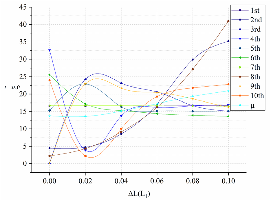
Taking the first 10 damping ratios as the comparative values when the damper locations are set at εi1 = 5%, Figure 8 shows the relationship between the average magnitude of change in the first 10 modal damping ratios of the system with rigid cross-ties and damper locations. From Figure 8, the damping ratio increases most rapidly with the non-dimensional position parameters of all dampers concurrently increase. In the MCHN system with rigid cross-ties, the increasing of non-dimensional damper location parameters on the longer cable yields more significant vibration reduction than on the shorter cable. Even when the installation locations of dampers are not all optimal, it is advisable to install dampers far from the anchorage end as possible to achieve the desired level of vibration reduction.

The relationship between the average change of the first 10 modal damping ratios and the damper locations.
Damping coefficient
The damper set at the cable end of a single cable-hybrid system often possesses an optimal damping coefficient, which can be obtained from the application of the general damping estimation curve. 6 However, in the MCHN system, due to the setting of the cross-ties, the modal shape is more complex, and the relationship between the damping coefficient and the damping ratio cannot be simply determined by the general damping estimation curve.
This study employs dampers with varying damping coefficients to investigate the variation in damping ratios for different modes. This approach can identify suitable damper parameters that enhance damping effects over a broader spectrum of modes. For analytical simplicity, all dampers can be standardized with identical damping coefficients.
To improve vibration control effect, an optimization evaluation criterion named Maximum Average Normalized Damping Ratio (MANDR) is proposed. This criterion ascertains the optimal damping coefficient by identifying the damping coefficient that corresponds to the maximum average value of the multi-order modal damping ratios. There are significant disparities among partial damping ratios, and the disparities affect the mean value of multi-order modal damping ratios. To mitigate the influence, normalization of each modal damping ratios is conducted prior to the calculation of the average damping ratio, as demonstrated in equation (21). The normalized damping ratio is denoted as


Setting two scenarios with Ψ = 300 and Ψ = 0.3 respectively. The non-dimensional damping coefficient parameters κi varies from 0.5 to 4.0, with other parameters remaining constant. Subsequently, the first 10 damping ratios are calculated and normalized, as shown in Figure 9.

The first 10 modal damping ratios and the optimization evaluated indices
As shown in Figure 9, within the range of non-dimensional damping coefficient being discussed, the modal damping ratio of each order initially rises and subsequently declines as the damping coefficient increases. Notably, the damping coefficients corresponding to the maximum damping ratios of each order mode are variable, suggesting that an increase in the damping coefficient does not consistently lead to an elevation in the damping ratio for every individual order mode. But the selection of the damping coefficient can be based on the principle of maximizing the average damping ratio of the considered order modes, which will effectively increase the damping ratios of the majority of the modes.
When Ψ = 300, it can be found from Figure 9(a) that the damping ratios of the third, sixth, and ninth modes are relatively higher, while the second and eighth modes are relatively lower, and the corresponding damping coefficients of the second and eighth modes are relatively small when their damping ratios show a decreasing trend. As shown in Figure 9(c) that after normalization, the numerical difference of damping ratio of different modes is obviously minimized, and μ has the maximum value when the non-dimensional damping coefficient κi = 2.5, and the difference from the maximum value is no more than 1.5% in the range of κi = 2.0–3.0.
When Ψ = 0.3, it can be found from Figure 9(b) that with the change of damping coefficient, the modal damping ratios of the first, second, and third orders tend to be similar, the fourth, fifth, and sixth order modes exhibit similar trends, and the seventh, eighth, and ninth order modal damping ratios are comparable as well.
Normalization was applied to obtain Figure 9(d). It is apparent that the trend of each modal damping ratio with respect to the damping coefficient remains unaffected, and the dispersion of damping ratio values diminishes, reiterating the effectiveness of normalization. When the non-dimensional damping coefficient is κi = 3.5, μ has a maximum value, and the difference between this maximum and other values is no more than 1.0% within the range of κi = 3.0–4.0.
Therefore, when the model employs rigid cross-ties and the damper locations are εi1 = 5%, the dampers with κi = 2.5 exhibit a better vibration control effect. When the model adopt flexible cross-ties and the damper locations are εi1 = 5%, the dampers with κi = 3.5 has a superior vibration control effect. Whether the cross-ties are rigid or flexible, provided that the deviation of the damping coefficients of the dampers from the optimal damping coefficients does not exceed a certain range, it can still exhibit an effective vibration control.
Cable length difference
The cable length difference between two adjacent cables, namely the cable length difference ΔL, is used to describe the length difference of the cables, and all adjacent cables have an equal cable length difference ΔL.
As shown in Figure 10, when rigid cross-ties are adopted, the damping ratio of each mode changes with the cable length difference. However, when flexible cross-ties are used, the vibration modes are mostly single-cable vibrations. Assuming that the non-dimensional location parameters of each damper remain constant, the damping ratio of each mode remains unchanged with the variation in cable length difference.
The influence of cable length difference on the damping ratio: (a) Ψ = 300 and (b) Ψ = 0.3.
For rigid cross-ties, if cable lengths are equal or the difference is small, certain modes exhibit low damping ratios, such as the second, third, eighth, and ninth modes for ΔL = 0, and the second, fourth, eighth, and tenth modes for ΔL = 0.02L1, as shown in Figure 10(a). This is due to lack of vibration in the cable segments with damper in these specific modes. As the ΔL increases, only the second and eighth modal damping ratios increase accordingly. While the damping ratios of other modes either decrease or show a pattern of initial decrease followed by an increase with the increase of ΔL. Nonetheless, when the difference in cable length is significant, all modes can achieve relatively optimal damping ratios.
The evaluation criteria MANDR is employed to analyze the first 10 order damping ratios of the MCHN system with rigid cross-ties, as shown in Figure 11. When the rigid cross-ties are used and the mass-tension ratios of each cable are identical, a superior vibration control effect can be attained with larger cable length difference. Although the vibration control effect is not entirely undesirable when the lengths of each cable are equal, it is advantageous to utilize cross-ties to connect cables with significant length differences.
Normalized damping ratios and mean values of the top 10 modes under different length difference degrees.
Mass-tension ratio
The influence of mass-tension ratio γ i on the damping ratio is discussed in a three-cable MCHN system with rigid cross-ties. The mass-tension ratio difference (Δγ) between adjacent cables is introduced, as shown in Table 4. With all other system parameters held constant, the study explores the influence of cable specifications and cable force variations on the damping ratio with different cable lengths difference. The first 10 order damping ratios with different mass-tension ratios and cable length differences are obtained, as shown in Figure 12.
Mass-tension ratio of each cable in the system.

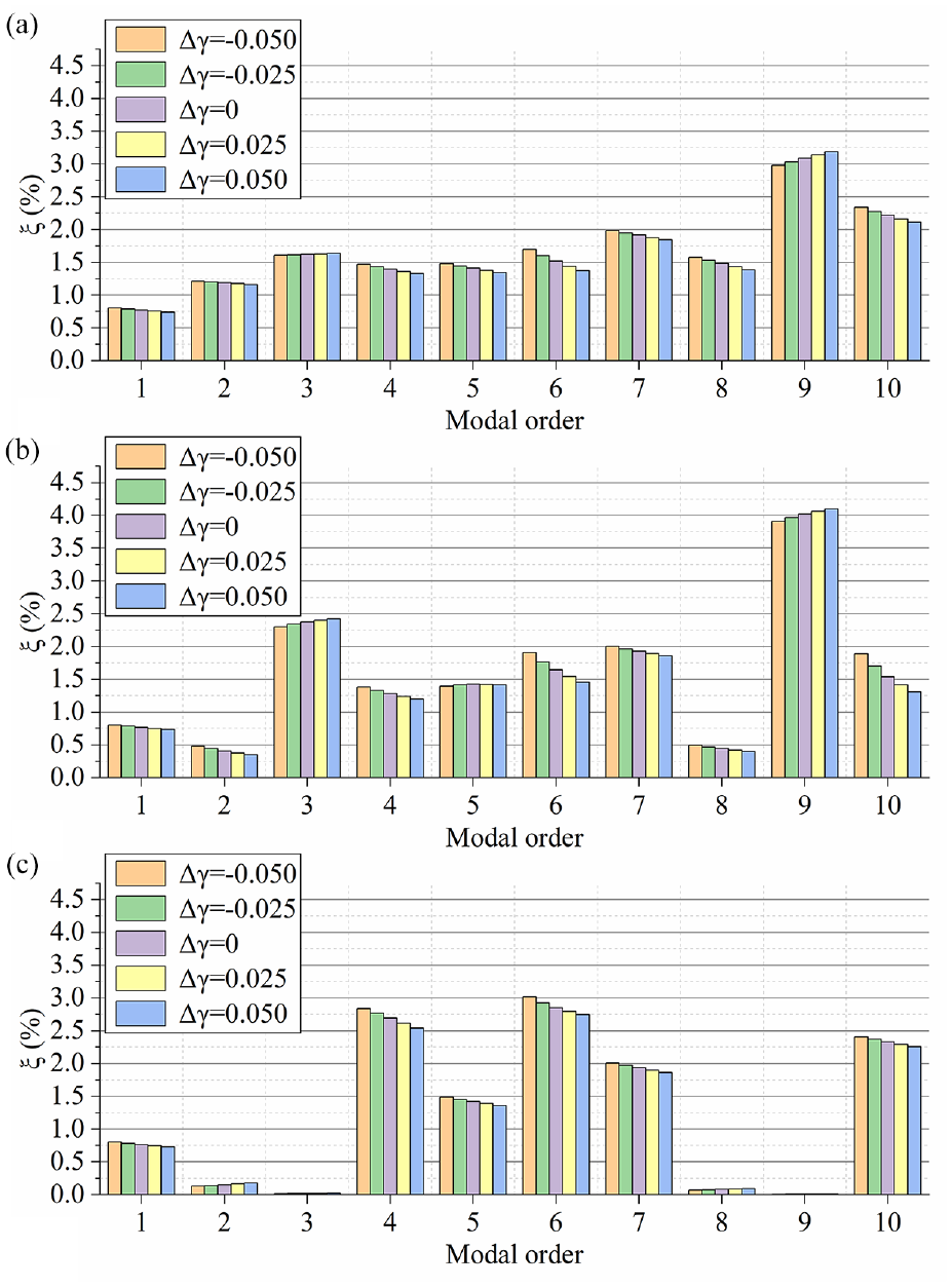
Damping ratios of the first 10 modes under different values of mass-tension ratio: (a) ΔL = 0.1L1,(b) ΔL = 0.05L1 and (c) ΔL = 0.
The vibration reduction effect varies when cables with different mass-tension ratios form a MCHN system, particularly exhibits a higher damping ratio for numerous modes when the mass-tension ratio of shorter cables is relatively small.
When the cable length difference is large, for the third and ninth modes, the damping ratio increases with the mass-tension ratio of the short cable. For other modes, connecting the target cable with short cables of higher mass-tension ratios leads to a decrease in damping ratio. For MCHN system formed by equal-length cables, if the target cable is connected to cables with higher mass-tension ratios, there exist modes where the damping ratio increases with the mass-tension ratio difference. However, for these modes, the dampers do not exhibit a substantial effect, such as in the second, third, eighth, and ninth modes.
When the frequency ratio meets
Conclusion
This study focuses on the multi-cable hybrid network (MCHN) system, where an analytical model for the MCHN system is established. Based on this model, the vibration reduction effects of various parameters, including the number of dampers, damper location, damping coefficient, cable length difference, mass-tension ratio, and cross-tie stiffness, on the in-plane natural vibration of cables are discussed. Through this analysis, the key findings are as follows:
The installation of dampers on each cable of the MCHN system ensures that the damping ratio for all modes remains non-zero, resulting in superior vibration control performance compared to cases where dampers are installed solely on selected cables. Notably, when stiffer cross-ties and more dampers are employed, the vibration control capabilities of the MCHN system undergo a significant enhancement. This finding offers a novel perspective for the design of MCHN systems.
In the MCHN system, the modal frequencies with dampers are typically higher than those without dampers, accompanied by alterations in some modal shapes. As the cross-ties become more rigid, the system exhibits enhanced vibration integrity. Conversely, with flexible cross-ties, the vibration is mostly manifested as single-cable vibration.
Enhancing the damping ratio of the MCHN system can be achieved by positioning dampers further from the anchorage end. When cross-ties are positioned at the mid-span of the stay cables, adjusting the damper locations toward the midpoint of the cables decreases the amplitude of certain damper-installed cable segments for specific modes, thus the damping ratio of those modes are reduced. When utilizing rigid cross-ties, positioning some dampers further from the anchorage end can enhance the vibration control effect, with particular notable effects observed for dampers on longer cables in MCHN systems.
This study innovatively proposes a multi-modal optimization criterion (MANDR), which maximizes the mean of normalized damping ratios across various modes, thereby enabling as many modes as possible to achieve satisfactory vibration reduction. The introduction of this criterion serves as a powerful tool for enhancing the multi-modal vibration control of MCHN systems.
In the MCHN system equipped with rigid cross-ties, relatively optimal damping ratios can be achieved across all modes with a considerable cable length difference. Connecting the target cable to shorter cables that have a smaller mass-tension ratio results in higher damping ratios.
Footnotes
Handling Editor: Sharmili Pandian
Author’s note
Zhuojie Zhang is also affiliation to Innovation Center for Wind Engineering and Wind Energy Technology of Hebei Province, Shijiazhuang, China.
Declaration of conflicting interests
The author(s) declared no potential conflicts of interest with respect to the research, authorship, and/or publication of this article.
Funding
The author(s) disclosed receipt of the following financial support for the research, authorship, and/or publication of this article: This work was supported by the National Natural Science Foundation of China (Grant No. 52178138), and the Natural Science Foundation of Guangdong Province (Grant No. 2024A1515012262).