
Abstract
With the prevalent application of the box girders in the express railway and urban rail transit systems, problems such as vibrations and noises of bridge structures caused by passing vehicles have increasingly aroused concerns than before, and thus, consequently damping fasteners are widely integrated into the design of track structures. In accordance with the vibration theory of slab track–box girder structures, and with reference to the change in types and parameters of damping fasteners, the article focuses on the probe into the effects of four common types of damping fasteners on the vibrations of box girders, by setting up the analytical model of spatial entity of track-slab–cement and asphalt mortar–concrete base layer–box girder coupled system and taking the velocity admittance of box girder as an evaluating index. The purpose of the study is to offer some feasible suggestions on a more scientific engineering designing in reducing the vibrations and noises. The calculating results show that (1) the stiffness of fastenings has distinct effects on the reduction in bridge vibration at 100 Hz and above, with Cologne egg rail fastening system as the best; but damping fastenings will stimulate stronger vibrations on rails in return. (2) The increase in damping on fastening system is not obvious to the reduction in bridge vibration, but in favor of vibration of rails above 60 Hz. (3) Within a certain frequency range, an anti-resonance phenomenon may emerge in the fastening system, which will undermine the damping effects or even reversely lead to an increase in structure vibration.
Keywords
Introduction
With the development of the high-speed railway and urban rail transit, it is the key point of controlling the vibration and noise pollution along the railway lines. In TGV Northern Line, the percentage of bridge length is 21.5% and 32.2% in TGV South-East Extension Line. In Joetsu Shinkansen, the percentage of bridges is 61.5%, and this value is continuously increasing. 1 In the Beijing–Tianjin Inter-city high-speed railway, the bridge length accounts for 87.7%, and in the Beijing–Shanghai high-speed railway with a length of 1318 km, there are 244 bridges amounting to a length of 1059.4 km, occupying 80.5% of the total length of the railway. 2 Till the end of 2015, the urban rail transit, open to traffic all over the world, had developed in length to 7500 km, among which elevated railways account for more than 61%. In some railway lines, such as Fangshan and Yizhuang Rail Transit Line in Beijing, Line 1 Light Rail Line in Wuhan, and Line 2 of Chongqing Light Rail, viaducts used in urban transit account for more than 85%.
When trains roll over railway tracks of the bridge, undesired vibrations and noise arise. On one hand, the environmental noises caused by railway, mainly derived from rolling trains and bridge structure, have become a nuisance for the people living close to the railway tracks.3–5 On the other hand, the intense contact force of wheel–rail and vibrations of the track components contribute to the deterioration of not only the track itself but also vehicles, bridges, and sometimes even damages the buildings and structures in the surroundings.1,6–8
To reduce environmental noises along railway lines and to decelerate the dynamic response of bridges, vibration attenuation components are installed in the vehicle–track–bridge system. For instance, resilient wheels, resilient track, and resilient roadbed are often used in rail transit. The rail fastening is mainly represented as a pair of linear springs and a viscous damper in parallel.9,10
In the literature, numerous studies have been carried out to obtain information about the effects of rail fastenings on the rail structure and substructure of track under working conditions. Fastening system is a key factor to the affection of vibration characteristics of a track. For soft rails, the coupling between rail and sleepers or track plates is weak, and the decaying rate of rail vibrations becomes slighter. Conversely, for stiff rails, the rail vibration is restricted by couplings between rails and sleepers or track plates, but vibrations of sleepers or track plates become intense.
As for the effect of fastening on track structure, it has been found that soft rail pads are favorable to transfer the loads to the sleepers and ballast, but wheel–rail contact forces are not always lowered. 6 In other models, 11 four track finite element (FE) models, with four typical fastenings, were developed. It was found that damping fastening track could only work at a certain frequency range, and the mode shapes indicated that at some frequency, there would be anti-resonance between the rail and base plate.
In terms of the analysis of fastenings and substructure of railways, the results showed that the mixed finite element method (FEM)–boundary element method (BEM) model is a good predictor, and the dominant frequency range varied between 40 and 80 Hz in which noises of the bridge structures emerged, mainly related to stiffness of the fasteners. 12 When the central frequency of subway tunnel environment vibration was below 25 Hz, dependence of frequency on stiffness of rail pad was slight. As it was less than 0.3 dB, the effect could be neglected. However, the frequency-dependent stiffness of rail pad would pose a significant impact on the high-frequency vibration response of near-field ground with a central frequency above 25 Hz.13,14
Analytical and numerical methods can be applied to discuss the influence of bridge vibrations caused by the fastenings. Based on the vibration theory of slab track–box girder structure, in this article, the numerical model of track-slab–cement and asphalt (CA) mortar–concrete was set up for the calculation of the velocity admittance, and the data were used for the analysis of the change in rail fastening parameters on the vibration transmission of the box girder. The results can provide guidance for the engineering designing on reducing the bridge vibration and noise.
The theoretical model of the track–bridge system
Velocity admittance is the ratio of the complex amplitude of the velocity response to stimulate that under harmonic excitation, namely, the velocity response under unit load, which is an important index for the structural vibration response. Admittance is a fixed value when the structure is a single-degree-of-freedom (SDOF) system, which reflects the vibration characteristics under unit load. Actually, train–track/bridge system is considered as a multi-DOF system, which can be taken as the linear superposition of two or more SDOF systems. Therefore, no matter how complex the structure is, the vibration response keeps unchanged under the unit load on the structural surface.
To calculate the dynamic performance of the track–bridge system, an elevated track–bridge model was set up, as indicated in Figure 1. The rail is connected to the viaduct by rail fastenings. The rail is streamlined into an Euler–Bernoulli beam with an infinite length, and rail fastenings are reduced to discrete and scattered springs with construction damping. The viaduct is simplified into a free beam with a finite length, which is supported by four elastic bearings. The bridge is simplified into an analytical beam model. A double track is laid on the bridge, with the interaction between two tracks overlooked. Only the right track and the viaduct are taken as research subjects. The dynamic flexibility method is adopted in the article to study the vertical vibration of the track. The dynamic flexibility refers to the displacement Y(z) caused by the simple harmonic unit load F(w) in its action spots, which can be shown in the following equation, namely, r = Y(z)/F(w).

The theoretical model of the track–bridge system.
As indicated in Figure 1, the simple harmonic load

According to the differential motion equation, yrj is the vertical displacement of rail j,
If the stationary response of track–bridge is taken into consideration solely, the result is
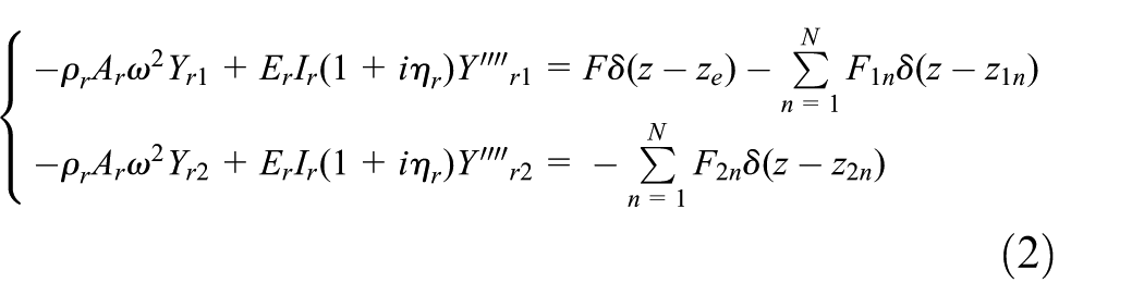
In equation (2), Yrj is the amplitude of the vertical displacement (complex function) of rail j; Fjn is the amplitude of load on the nth rail fastening at rail j and j stands for 1 and 2; the marker “′” means performing the differential of vertical coordinate.
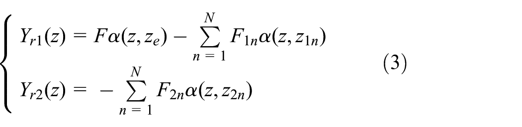
The displacement of rail is superimposed displacement of all the loads, and the displacement caused by each load equals the product of the load and its dynamic compliance. According to this principle, the stationary displacement response of Rail 1 and Rail 2 can be shown as follows

The equation
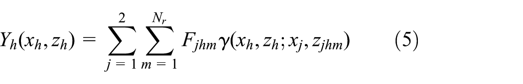
Similar methods are used in the solution of the stationary displacement response of viaduct bridge h
When
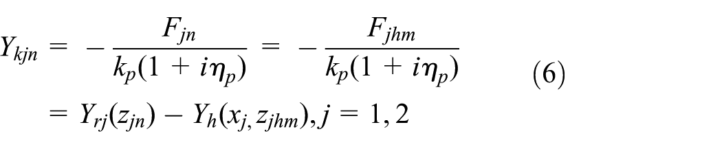
Substituting equations (2), (3), and (5) into equation (6), respectively
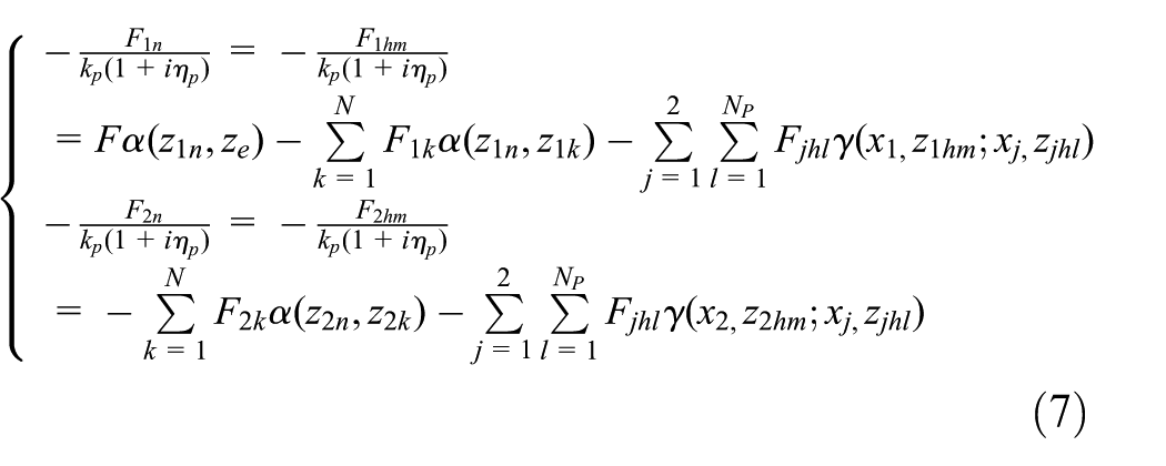
Equation (7) can be represented in matrix, RF = Q, where R is the velocity admittance of the viaduct–track system; F is the force on all the rail fastening at Rail 1 and Rail 2; the top N element of Q is
According to the formula above, the force of rail fastening can be worked out, and then by substituting it into equation (3), the vertical displacement amplitude

The FE model of track–bridge system
Because the lateral attitude of the wheel–rail contact force deviates from the symcenter of the bridge structure, torsional vibration will occur in the viaduct structure when the two-way tracks are laid in the bridge with single box and room. In addition, there are some partial models in box girder viaduct structure of tens of Hertz to hundreds of Hertz which influence the structure vibration and noise radiation. Therefore, more complex models are needed in studying the vibration problems of viaduct structure.
Establishment of the FE model
Taking the 32-m track–box girder structure as the research subject, the Beam188, Combin14, and Solide45 are simulated as the track, fastening systems, structures of bridge, and so on, respectively. To analyze the transmission attenuation law of the vibration in the range of track structure to bridge structure and the impact of different parameters in vibration transmission, the entity model of track-slab–CA mortar–concrete base layer–box girder coupled system was set up to calculate the velocity admittance of the box girder in which full method will be used in the model and the calculation with the frequency from 0 to 800 Hz. The midpoint on the left rail of the right track was selected as the incentive point. The reflection point will lie the flange, the web, and bottom of the bridge’s midsection; the detailed positions are shown in Figure 2, and the parameters of the model are shown in Table 1.
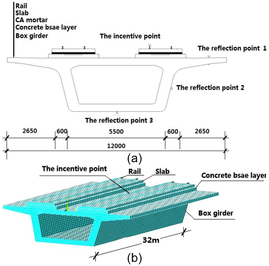
The FE model of track–bridge system.
The parameters of track–bridge system.

Validation of the model
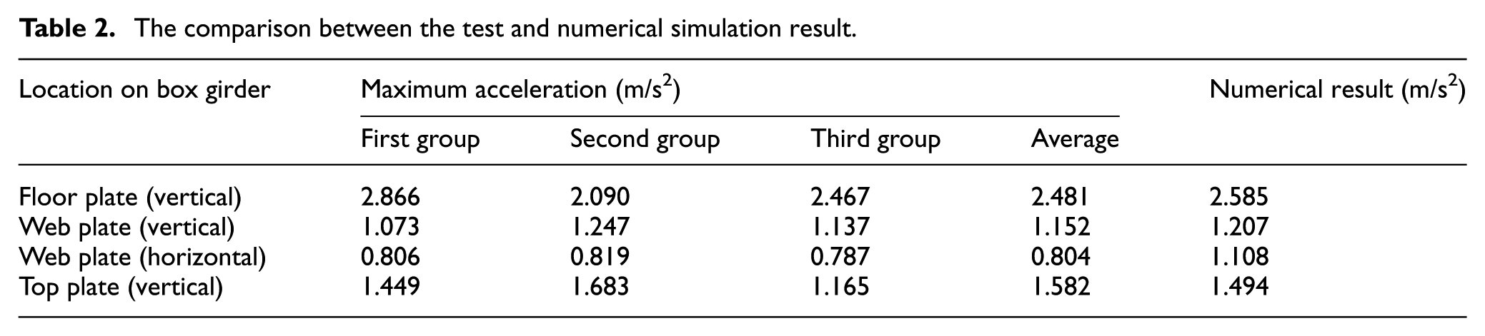
A vibration response test on the box girder was described in Chong; 17 the arrangement of measuring points is on the flange, web plate, and bottom plate, and the trains run on the box girder run at 60 km/h at the same time; the picture of vibration test is shown in Figure 3. To verify the correctness of the FE model of track–bridge system, the actual measurement data of dynamic wheel/rail loads were imposed on the model for calculating the vibration responses on the bridge section 18 (see Figure 4). According to the results shown in Table 2, the calculating results are basically in line with the changing regulation of numerical simulation and the proportion is close in horizontal and longitudinal.

Picture of the vibration test.
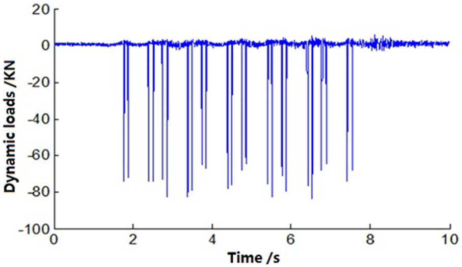
Dynamic loads.
The comparison between the test and numerical simulation result.
The numerical calculation and analysis
The parameters of some key parts including rail fastenings, CA mortar layers, and bridge bearings are crucial to the design of the bridge structure on elevated track with regard to the vibration damping and noise reduction. The FE model is analyzed based on the vibration of the ballastless track–box girder structure. Moreover, the article analyzes the vibration transmission properties from the track slab to the bridge structure and considers specific conditions of using spot CA mortar layers and bridge bearings, so as to make an analysis of impacts that the stiffness and damping of fastenings have on the vibration of track–bridge system.
Analysis of bridge vibration responses influenced by the selection of rail fastening
A rail fastening refers to the component connecting rails with sleepers, which is also called the intermediate fastenings. Rail fastenings used in urban rail transit are assorted. For example, Vossloh300, Pandrol Fastclip, Cologne egg, WJ series, DT series, and elastic rods I, II, and III are the case. The rail fastening can be divided into three classes in terms of its stiffness, namely, low-stiffness, middle-stiffening, and high-stiffness fastenings. To study the impact that rail fastening system has on the vibration of the rail–bridge structure, four kinds of commonly used fastenings have been selected in this article to make a comparison and analyze. Four kinds of fastenings and their parameters are as follows: Cologne egg fastenings (stiffness of 10 kN/mm), GJ-III vibration damping fastenings (25 kN/mm), DTVI2 fastenings (50 kN/mm), and E-shaped fastening systems (60 kN/mm). Figure 5 exhibits and compares impacts that different types of fastenings have on the vibration of bridges. As seen from Figure 5(a)–(c), the impact of the rail fastening is almost negligible for the bridge vibration within 60 Hz. When it comes to the bridge vibration within the range of 60–100 Hz, the E-shaped fastening system which boasts high stiffness produces the minimum impact on different parts of the bridge structure, while the GJ-III vibration damping fastening brings the largest effects. However, the differences between vibration amplitudes of these four kinds of rail fastenings are subtle. A lot of studies show that anti-resonant vibrations will occur between the rail and the fastening system during a certain frequency range, making the stiffness under track greater than its static stiffness, rendering the rail fastening system lose its damping effect and even intensifying the structure vibration. For the bridge vibration above 100 Hz, the GJ-III vibration damping fastening is deemed the best concerning the vibration reduction in the box girder, while the E-shaped fastening system records the worst performance in the vibration reduction. As is apparent from Figure 5(d), the impact the fastening system has on the vibration of rails can be divided into two frequency ranges, with one within 100 Hz and the other over 100 Hz. The E-shaped fastening system is more effective than the other three kinds of rail fastenings within 100 Hz, while the GJ-III vibration damping fastening is better than the others in the reduction in vibration above 100 Hz.

The viaduct velocity admittance with different rail fastening systems: (a) reflection point 1, (b) reflection point 2, (c) reflection point 3, and (d) the incentive point.
Analysis of bridge vibration responses influenced by the damping of rail fastening
When the vibration wave travels through the rail to the bridge, the vibration energy will be partly dissipated by the damping of the rail fastening, and the energy delivered to the bridge structure dwindles, fulfilling the purpose of vibration damping. To analyze impacts that the damping of rail fastenings have on the vibration of bridge structures, four figures for the damping of rail fastenings including 1 × 10⁴, 2 × 10⁴, 4 × 10⁴, and 8 × 10⁴ N/(m/s) are selected, respectively, with the stiffness of 60 MN/m remaining unchanged, to calculate the velocity admittance of different parts of the bridge. The graph five shows the calculation results. Comparing Figure 6(a) with 6(c), it can be observed that increasing the damping of rail fastening is of no effect in the reduction in the bridge vibration within 100 Hz, while for the bridge vibration between 100 and 300 Hz, the damping of fastenings has a certain effect on vibration reduction despite the fact that the reduction amplitude is relatively small. The effect is just the reverse when the bridge vibration is above 300 Hz, and damping four gives rise to the strongest vibration. The damping is obviously effective in reducing the rail vibration over 60 Hz. As seen from Figure 6(d), damping four ranks first in the vibration damping, and damping three, damping two, and damping one see a dwindling effect in reducing vibrations successively.

The viaduct velocity admittance with different rail fastenings’ damping: (a) reflection point 1, (b) reflection point 2, (c) reflection point 3, and (d) the incentive point.
Conclusion
In this study, the analytical model of spatial entity of track-slab–CA mortar–concrete base layer–box girder coupled system was first set up on the basis of the vibration theory of slab track–box girder structure. Then with reference to the velocity admittance of the track and bridge structure, an analysis was conducted on the vibration transmission on track and bridge structure and the impact of each key parameter on vibration transmission. From what has been analyzed above, the following conclusions are drawn:
The stiffness of fastenings has distinct effects on the reduction in bridge vibration at 100 Hz and above, with Cologne egg rail fastening system as the best, but damping fastenings will stimulate stronger vibrations on rails in return.
The increase in damping on fastening system is not obvious to the reduction in bridge vibration, but in favor of vibration of rails above 60 Hz.
Within a certain frequency range, an anti-resonance phenomenon may emerge in the fastening system, which will undermine the damping effects or even reversely lead to an increase in structure vibration.
Footnotes
Academic Editor: Crinela Pislaru
Declaration of conflicting interests
The author(s) declared no potential conflicts of interest with respect to the research, authorship, and/or publication of this article.
Funding
The author(s) disclosed receipt of the following financial support for the research, authorship, and/or publication of this article: The work was supported by the National Natural Science Foundation (51268015) and The landing plan of science and technology of Jiangxi Province Higher Education Institutions (KJLD14038).