
Abstract
The telescopic boom structures are extensively utilized in engineering applications involving large mobile cranes, aerial work platforms of significant height, and similar mechanical devices. These are predominantly fabricated using solid-webbed box types, latticed truss designs, or a combination thereof. Under load, they exhibit pronounced geometric nonlinear effects, with the relationship between load and displacement demonstrating marked nonlinear characteristics. This paper focuses on the geometric nonlinear modeling of slender multi flexible beam structures. The overall structural system is divided into several substructures, and the concept of multi flexible system modeling is borrowed to establish a follow-up connected body foundation on each substructure. By decomposing the node displacement and rotation in the substructure, the large displacement and large rotation of the node are decomposed into rigid body motion of the connected base and small displacement and small rotation relative to the connected base, effectively representing the large displacement and large rotation of the substructure as rigid body motion of the connected base. A modeling method for the geometric nonlinear analysis of slender and flexible multibody beam structures is proposed. By decomposing the nodal displacement and rotation within the substructures, the large displacement and rotation of the nodes are broken down into the rigid body motion of the body-fixed coordinate and small displacement and rotation relative to the body-fixed coordinate. This approach establishes the application conditions for calculating the structure’s virtual power of deformation using traditional beam elements with linear strain. A method for solving the instability load of slender and flexible multibody structures is proposed. This method integrates the characteristics of the system’s nonlinear equilibrium equations with respect to load, by deriving the system equations with respect to a load increment control parameter. This paper converts nonlinear equilibrium equations into first-order ordinary differential equation (ODE). The method proposed in this paper provides a more efficient solution for the buckling load of the telescopic boom. It can be used to systematically and quickly calculate the structure of the telescopic boom.
Keywords
Introduction
Mobile cranes are widely used in various fields of construction machinery due to their strong flexibility and wide extension range. As shown in Figure 1, the telescopic arm structure, as its main load-bearing component, plays an irreplaceable role.1–3 The lifting height during actual work can reach tens or even hundreds of meters. The extended structure of the telescopic arm is usually a slender structure with obvious geometric nonlinear effects. In addition, the stability of the structure is also the main factor limiting lifting performance.

Examples of telescopic booms for mobile cranes.
A large number of relevant studies have been accumulated in the structural analysis of telescopic boom,4–7 which have solved a lot of theoretical and practical engineering problems, among which a considerable part of the work is to complete the finite element modeling of the entire structure directly by using the shell element in commercial software, while the huge degree of freedom and complex contact constraints often seriously affect the computational efficiency and convergence. In many existing literatures and specifications,8–13 the telescopic arm is regarded as a ladder column with variable section, and its deformation and instability are solved by energy method, Rayleigh-Leeds method and precise finite element method, etc. Ali Faghidian study a stationary variational framework of the Timoshenko–Ehrenfest beam founded on the elasticity theory, And a lot of valuable conclusions were obtained.32,33 In essence, the problem of a single component with changing section is still stuck in the problem of a multi-structure complex telescopic arm composed of multiple hollow monomers with changing section thickness is rarely studied. Akano and Olayiwola34,35 has conducted in-depth related research and obtained many valuable conclusions. Moreover, this equivalent step beam model adopts the common method of superposition of bending and torsional modulus of overlapped parts in engineering, which will undoubtedly produce false constraint reaction in the overlapped parts.
In engineering, the long and thin structure after bearing loads shows large deformation as a whole, but it is still in the category of small deformation in a local area. Considering this feature, many experts and scholars have proposed corresponding geometric nonlinear calculation methods.14,15 Compared with the TL schema of the early reference initial configuration and the UL schema of the current configuration,17–19 the co-rotation coordinate method 16 presents simple and efficient advantages: it can apply the existing linear elements without the construction of complex nonlinear elements, and is favored by engineering designers.20–22 Ali Faghidian proposed a new approach for inverse reconstruction of eigenstrains and residual stresses in autofrettaged spherical pressure Vessels.30,31
In the existing design codes, for the whole stability calculation of long and thin compression bending members,23–27 the section bending moment is often amplified by the magnification factor, so as to consider the geometric nonlinear influence of the structure, and the stability problem is transformed into the equivalent stress calculation problem. However, this method is only a simplified load verification method, which cannot fully reflect the actual geometric nonlinear effect of the structure or accurately predict the instability load, nor can it provide the equilibrium path curve of the solution process. Therefore, it is meaningful to develop a solution strategy for unstable load that does not depend on the initial value of the nonlinear equation and can automatically adjust the incremental load step. Ali Faghidian and Tounsi study the dynamic characteristics of elastic nanobeams within the context of the mixture unified gradient theory of elasticity.
The telescopic boom structure is characterized by combination rules and many calculation conditions, which often requires a large number of performance calculations. Therefore, the problem worth studying is whether the stability critical load of the structure can be quickly searched by reducing the degree of freedom as much as possible on the premise of accurately describing the geometric nonlinear effect of deformation and the nested constraint relationship between the arm segments. The substructure is established with the contact section nodes and cylinder hinge joints as the boundary points. The internal node freedom of the substructure can be represented by the boundary node freedom through the internal equilibrium equation, and then converted to the formal two-node super element. Considering that the telescopic boom structure is in line with the constraints and boundary conditions of the actual equipment, the structural nonlinear balance equation including lifting load parameters and the corresponding tangential stiffness matrix are established by taking the degree of freedom of the super element node as the system variable.
A modeling method for geometric nonlinear analysis of slender multi-flexible beam structures is proposed. Based on the modeling theory of multi-flexible system, the flexible structure is divided into several sub-structures, and a continuous base is established on each sub-structure. By decomposing the node displacement and rotation in the substructure, the large displacement and rotation of the node are decomposed into the rigid body motion of the connected base and the small displacement and rotation relative to the connected base. Thus, the application conditions of calculating the virtual power of structural deformation using the linear strain of traditional beam elements are established. Finally, the differential form of the equilibrium equation is used to quickly solve the deformation equilibrium path and instability load of the structure.
This paper is organized as follows: Section 2 describes the process of rope element discretization between pulleys, and provides a generalized mass matrix and force matrix considering model noise reduction. Section 3 describes how to establish a pulley block model. Section 4 details the calculation method for strain in the rope section in contact with pulley. Section 5 provides the boundary conditions for the driving drum and a method for handling system constraints that are not independent. Three numerical examples are presented in Section 6 to validate the proposed method. Section 7 summarizes some conclusions and recommendations for complex systems containing pulley blocks.
Splicing method of beam element with variable section arm
The length of the arm segment of the telescopic arm structure is much larger than the section size, which is a typical hollow slender structure, so the arm segment can be modeled by common beam elements. As shown in Figure 2, the deformation virtual power of the beam element

Where


Two-node spatial beam elements.
Under the condition of small strain, the stiffness matrix in equation (1) is a constant matrix.The gravitational virtual power in the direction g

It should be noted that the joint parameters of the traditional linear beam element stiffness matrix and the gravity influence matrix are both the centroid displacements of the left and right ends. However, in view of some specific problems, the node parameters are often selected to reflect the structural cross-section shape of the feature points as nodes, as shown in Figure 3, Ali Faghidian study the smoothed inverse eigenstrain method for the reconstruction of residual fields from limited residual strain measurements in axially symmetric stress state.20–22 The common variable section of the arm is composed of the upper cover plate and the lower cover plate, part of the regular shape, the whole of the irregular shape. In addition, the thickness of the lower cover plate may change at a certain length along the axis of the arm segment, and the change in the thickness of the arm segment will only affect the mass distribution of the section and the change of centroid coordinates, but will not affect the change of the relative position of the selected feature points, so that there will be no non-coincidence of shared nodes caused by the change in section.

The change of cross-section.
In view of this type of cross section, the cross section coordinate system is usually established at the center of the semicircle of the lower cover plate, and it is more appropriate to choose the displacement u1 and u2 of the origin of the coordinate system as the description variables. The coordinates of the section centroid in the section coordinate system are

among6
The deformation virtual power and gravity virtual power of the beam element are not at the center of the node

among

The section is established by selecting suitable section feature points as nodes.The displacement coordination between the centroid and the node realizes the variable section of the arm splicing of each beam element. As shown in Figure 4, when considering the first arm segment with variable amplitude cylinder support and over-mast connection, since its structural characteristics contain constraints and external connecting elements, the location of these constraints and external connecting elements must be defined as the boundary node of the substructure to ensure the accuracy and effectiveness of the substructure division.
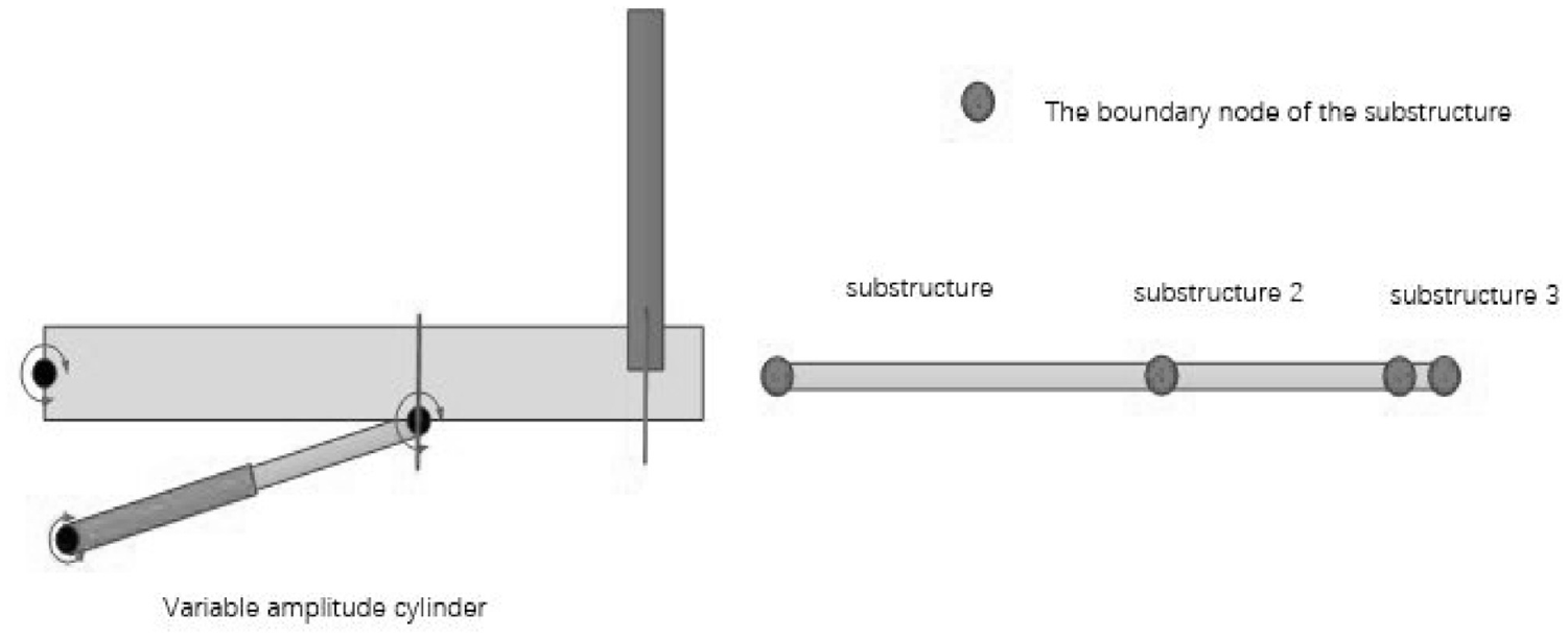
Examples of substructures.
Displacements of substructural elements and condensation of degrees of freedom
The elongated characteristics of the telescopic arm often lead to the phenomenon of large displacement and large rotation after loading, and the linear analysis results may be obviously inconsistent with the reality. Aiming at the geometric nonlinearity of slender structures, the corotational coordinate method first proposed by Wempner 28 and Belytschk 29 decomposed the displacement field of elements into rigid body rotation with the element coordinate system and small displacement relative to the element. Such units also show obvious advantages in specific applications. 15 But on the other hand, it is the same as the traditional method, if the nonlinear analysis is to be done, all the elements in the structure must be treated as nonlinear elements, and finally the structural equilibrium equation is a set of nonlinear equations with high dimension. In fact, according to the characteristics of the telescopic arm structure, each arm segment can be reasonably divided into several substructures. The geometric nonlinear effect is mainly reflected in the large displacement and rotation of the connected coordinate system of the substructure. The displacement rotation of each node in the substructure relative to the connected coordinate system can be treated as small displacement and small rotation.
The substructure shown in Figure 5 consists of

among


Beam elements in the substructures.
The left-most section coordinate system

Its rate of change

Among them, the vector radius


The global virtual velocity of freedom of any point inside the substructure is decomposed into the translational rotational freedom of the substructure connected coordinate system and the local virtual velocity of freedom of the current connected coordinate system. In order to transform the virtual power equation into an algebraic equation, it is necessary to give the functional relationship between the global degree of freedom and the global degree of freedom because the local degree of freedom in the connected coordinate system is inconsistent with the global degree of freedom in the global coordinate system. The displacement of the beam element nodes in the connected coordinate system of the substructure can be expressed as

Its rate of change

The corresponding local rotation angle

Its rate of change

The displacement Angle of the node in the leftmost section is zero relative to the connected coordinate system of the substructure, and the displacement Angle of all nodes described in the connected coordinate system of the substructure is small displacement and small rotation, which meets the characteristics of linear beam elements. Moreover, the nodes in each substructure can be divided into two categories: (1) boundary node sets

Telescopic arm structure and substructure.
In the substructure coordinate system, the stiffness array of each beam element is assembled and divided according to the freedom of internal node and the freedom of boundary node.
Deformation virtual power

where,

Physical virtual power


It can be inferred from this

After the arm segment is divided into multiple substructures, the large displacement rotation of the arm segment can be described as the large displacement rotation of the substructure coordinate system. The deformation of the beam element in the substructure coordinate system is small deformation, so it can be considered that the displacement and rotation of the element node in the substructure coordinate system is small. Under this condition, the elements in the substructure stiffness matrix are constant, so

Substituting equations (27) and (28) into equation (22) yields

Physical virtual power

Among them, the incidence matrix

The equivalent stiffness matrix and equivalent gravity influence coefficient are expressed as

In this way, the substructure assembled by splicing
Substructure division of telescopic arm and parallel constraint processing
The connection between the arm segment and the arm segment in the telescopic boom structure is different from the traditional multi-object structure. The common multi-object structure is connected in series by the constrained typical local rigid area, which can be called series connection. The telescopic arm structure is a system composed of multiple hollow structures surrounded and nested by layers. The sliding movement of the arm section along the axial direction is constrained when working, and the whole arm section is a flexible body that can undergo large deformation. This connection can be called parallel connection. As shown in Figure 5, each arm segment of the telescopic arm is connected through a pin hole. Although there are gaps between them, they are very small compared with the section of the arm segment. In addition, when the bending modulus of each arm segment is of the same order of magnitude, the contact area is confined to the narrow area of the left end of the inner arm and the right end of the outer arm.
Each arm segment has at most four sections affected by other arm segments: the left end face connecting the pin shaft, the section contacting the right end face of the outer arm, the section where the pin hole is connected to the inner arm pin, and the right end face contacting the inner beam. These four special section nodes can be called the left end node, the outer contact point, the inner contact point, and the right end node. According to this feature of the telescopic arm, the four nodes are used as boundary points to divide the substructure of each arm segment, and multiple beam elements can be further divided within each substructure. In this way, a complex telescopic arm structure with m arm joints can be geometrically nonlinear analyzed by
As shown in Figures 7 and 8, taking arm segment 1 and 2 as an example, there are two types of constraint relations between adjacent arm segments: (1) The pin slider constraint between the left section of the inner arm 3 and the inner contact section 1 of the outer arm; Second, the right node section of the outer arm 2 and the outer contact point section 4 of the inner arm are bound by the slider lap. Here, the node vector diameter and Angle corresponding to the section are expressed as

Substructure division of the telescopic boom system.
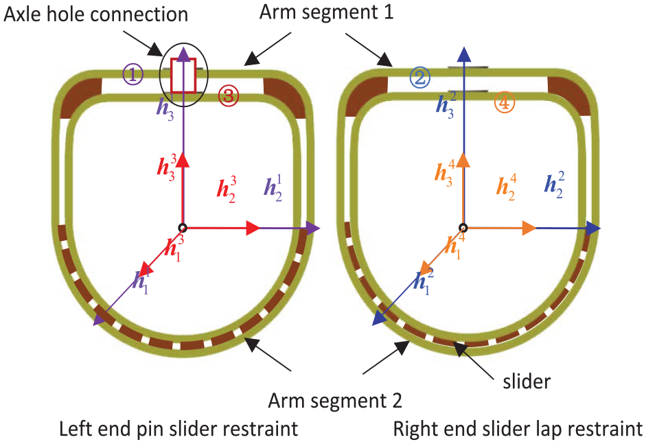
Constraints between booms.
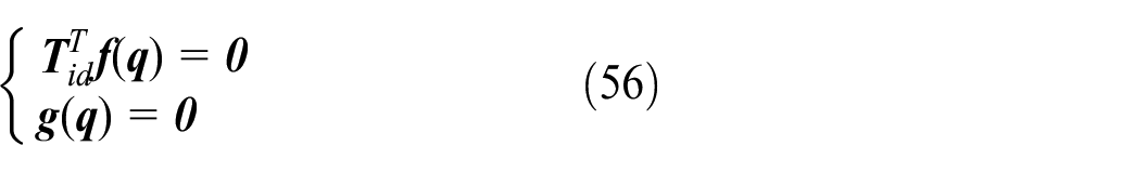
In the first type of constraint relation, the relative motion of the section ①③ is limited by the pin connection of the shaft hole and the middle slider, which means that the axial vector
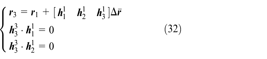
Where,
In the second type of constraint relation, the sliders between the sections ② and ④ limit the relative translation along the main axis of the section and the relative rotation around the plane normal, which has the characteristics of prismatic hinge in the theory of multi-body systems, and the corresponding constraint equation can be written as

According to equation (34),
Additional structural constraint relation and equivalent nodal force
The boundary conditions of traditional structural problems are usually directly constrained displacement, and the methods for dealing with such constraints have been very mature; This degree of freedom is determined by the joint deformation of the arm segment and the fixed length of the variable amplitude cylinder support in the working state. In addition, the external force received by the arm section not only includes the self-weight and the lifting weight, but also includes the additional external force exerted by the arm head and the lifting rope. The external force exerted by these additional structures on the arm segment is not only related to the displacement of the external force on the structure, but also to the motion of the constraint structure itself.
Fundamental arm boundary constraints
The hinged part of the turntable and the basic arm is shown in Figure 9. Due to the high concentration of force on the pin position, it will be reinforced and welded to the left end face of the arm joint.

Connection between basic boom and turntable.
There is a constraint relation between the node vector diameter of the left section

Where,

The lower hinge point of the variable amplitude cylinder is hinged with the turntable, and the upper hinge point is hinged with the basic arm. In the working state, assuming that the length of the cylinder remains constant, essentially a fixed distance constraint is formed between the upper and lower hinge points. The upper hinge point can be represented by the node vector diameter

Where

Where
Arm head, lifting weight, lifting rope additional joint force
The boom head of the mobile crane telescopic arm is welded on the right end face of the innermost arm, as shown in Figure 10. One end of the lifting rope is connected to the winch on the turntable, and the other end is tangent to the surface of the guide wheel.

Connection between boom head and rope.
The innermost arm section node connected to the arm head is represented by


After the lifting rope bypasses the guide wheel, it is connected with the

Convert to adding equivalent node force at node

Structural equilibrium equation and tangential stiffness matrix
The degree of freedom of the substructure boundary nodes after the condensation of each arm segment is taken as the system variable, which is divided according to translation and rotation, and the overall virtual power equation of the telescopic arm structure can be expressed as

Where


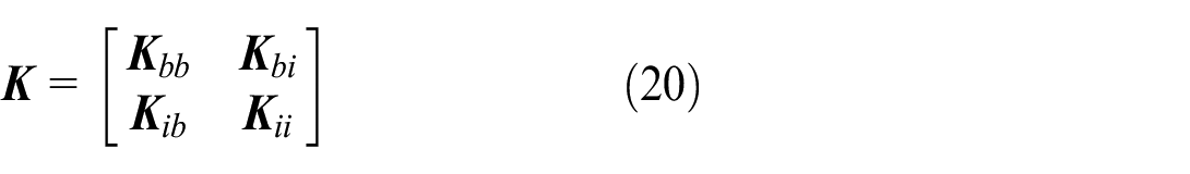
In the formula, the submatrices


Where

The virtual power equation corresponding to the equivalent nodal force and moment of substructure

By defining the system description variable

Without loss of generality, the constraint equation of the structure can be expressed as

According to the constraint relation between adjacent arm segments and the boundary conditions, the system variables can be divided into two parts: non-independent and independent

The variational constraint equation derived from equation (52) can be expressed as

Nonindependent parts virtual variational can be represented by independent parts, there is a relationship

Thus, an algebraic equation for solution can be obtained from the virtual power equation (51)

At this time, the number of equations is the same as the number of independent variables, and it is necessary to add independent equations with the same number of non-independent variables to satisfy the solution completeness. By combining the equilibrium equation (56) and the constraint equation (52), the equation required to solve the overall parameters of the node can be obtained
This is a set of highly nonlinear equations, giving the corresponding tangential stiffness matrix can greatly improve the solving efficiency. In order to obtain the tangential stiffness matrix of the equilibrium equation, the differential form of equation (56) needs to be given

In the first term of the equation

Relates to the resultant resultant moment


The relation between the differential of the local parameters of a node and the global parameters can be obtained by equations (46)–(47). namely


The second term of the formula requires the substitution of generalized forces

Where

By substituting equations (59)–(65) into equation (58) and combining with equation (66), the desired tangential stiffness matrix can be obtained. According to the principle of virtual power, the steps of finite element are as follows: 1. To obtain the expression parameters of each substructure; 2. Each substructure is assembled to form the whole finite element equation (57), and the constraint equation is written out to obtain the final finite original equation. 3. Find the Jacobi matrix of the whole equation.
Differential form of structural nonlinear equilibrium equation
The equations for solving the deformation of the telescopic boom structure are highly nonlinear, and the selection of initial values seriously affects the convergence of the iterative results. The lifting load is the main parameter that causes the change of joint displacement. By tracking the balance path of the telescopic boom structure under different lifting loads, the deformation corresponding to any load and the final instability load can be quickly obtained. The balance equation of the overall telescopic boom structure can be written in the following form 2

Where
The traditional load increment method increases the applied load step by step in multiple load steps, and the calculation result of the previous step is used as the initial equation value of the current step, which greatly improves the degree of convergence and then tracks the balance path. However, this method needs to set a fixed load increment manually, which is too small to increase the calculation amount and reduce the calculation efficiency. Too large and may fail to converge; Moreover, because the region of the unstable load cannot be accurately judged in advance, too large load increment is likely to directly cross the extreme point, resulting in failure to search the unstable load.
In view of this, this paper considers the derivation of the balance equation of the telescopic boom structure to the load control parameters and converts it into a differential equation. By taking advantage of the automatic adjustment of the step length in the conventional differential equation solver, the function of automatically adjusting the load step size according to the nonlinear degree corresponding to the current load state of the system is realized. On the premise of ensuring the convergence of the solution of each step, Fast tracking of balance paths and search for unstable loads. Its main operations are as follows:
(1) The structural equilibrium equation (67) takes the derivative of the load control parameters to obtain the differential equation

In the formula, ass is the tangential stiffness matrix of the equilibrium equation, and frd exactly reflects the nonlinear degree of the displacement-load curve under the current load.
(2) According to the equilibrium equation (67), the displacement angle
(3) Given the upper limit of the load control coefficient
(4) Trigger the termination condition (5), calculate the termination, and obtain the unstable load and the equilibrium path from the loading to the unstable load; Without triggering the termination condition (5), calculate to
(5) If the system encounters extreme point instability, the method of solving the differential equation cannot pass the extreme point, and the numerical performance is that the derivative of the displacement to the load coefficient tends to infinity, so it can be set

Where
With the advantage of automatic adjustment of the step size by the conventional differential solver, the method can be solved quickly in a relatively long step during the initial load increasing stage (linear deformation stage). At the same time, in the near instability stage, the rapid automatic adjustment gradually approaches the instability load in a small step. The comprehensive performance of the telescopic boom is determined by both the instability load and the strength failure load, but the search of the instability load is the premise of the calculation of the failure load, and the former provides a lot of data for the latter, so the calculation and search of the failure load can be further completed on this basis.
Firstly, based on the analysis of the characteristics of the equilibrium path curve, the slope ratio is established as the criterion for judging the instability load. On this basis, a new method to solve the instability load is proposed, that is, the problem of solving the nonlinear equilibrium equation of the system is transformed into the problem of solving the initial value of ordinary differential equation. This method can directly calculate the slope of the displacement (Angle) relative to the load in the equilibrium path curve, and capture the key characteristics of the unstable load effectively.
Numerical examples
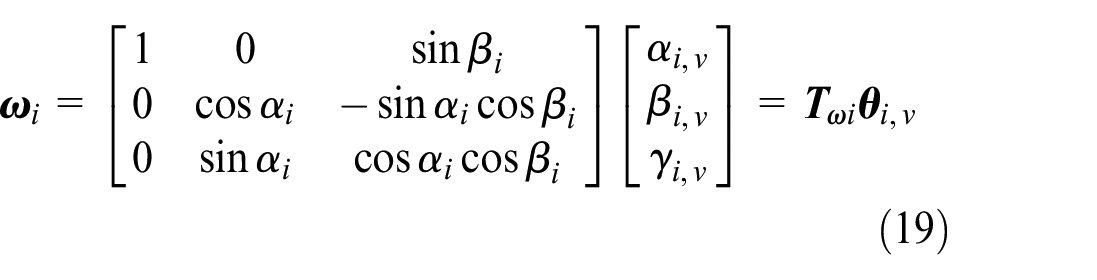
According to the derivation in the third section of the article, the telescopic arm is divided into multiple individual flexible bodies, and the connected foundation of the individual flexible bodies is established using the Cardan angle. Thus, the deformation of a single flexible body is decomposed into the deformation of the connected base in the overall coordinate system and the elastic deformation inside the connected base.
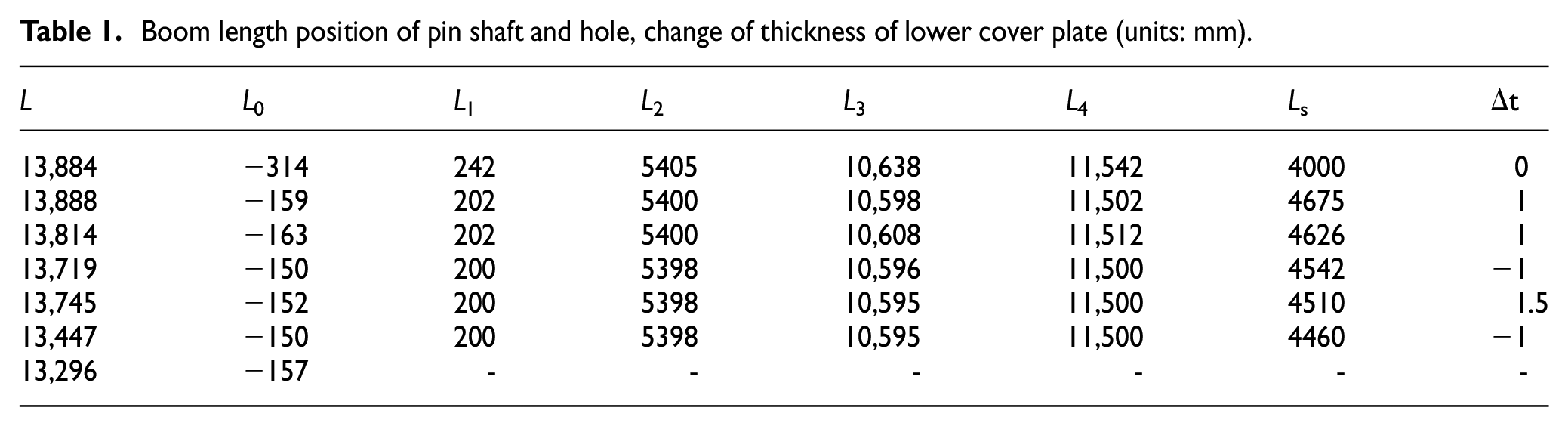
Figure 11 shows a mobile crane expansion boom structure composed of seven U-section boom segments with an elastic modulus of 2.1 Pa × 1011 Pa, Poisson’s ratio of 0.3, and a density of 7850 kg/m3. The length of the arm section is L, and each arm section contains 1 pin shaft and 4 pin holes (from left to right, the pin hole numbers are 1,2,3,4), which are recorded as

The telescopic boom for mobile crane.
Boom length position of pin shaft and hole, change of thickness of lower cover plate (units: mm).
Cross-sectional size of boom (units: mm).

Moment of inertia of arm section
According to the geometric characteristics of the section form shown in Figure 9, the center of the semicircle of the lower cover plate is selected as the section node. The section can be divided into several regular shapes with respect to axial symmetry.

At the same time, the mass and centroid of each section are calculated respectively, and the mass
(1). Calculation parameters of cross section before thickness change of lower cover plate (International unit).

(2). Calculation parameters of cross section after thickness change of lower cover plate (International unit).

Division of arm joint substructure
Taking the cross section node of sliding block contact between arm joints and the hinge section node of variable amplitude cylinder as boundary points, each arm section is divided into substructures as shown in Figure 12 along the length direction, in which node No. 3 is the node of cylinder connection cross section, the innermost arm is divided into two substructures, and the rest arms are divided into three substructures. A total of 27 nodes and 20 substructural super units are required for the 7-section arm to be divided.
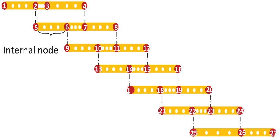
Substructures’ division of the telescopic boom.
Deformation of telescopic arm structure under different working conditions
The deformation results under different working conditions were obtained using the method proposed in this paper for the telescopic arm structure shown in Figure 9. The specific working condition selection is shown in Table 5, where
Calculated working condition.

According to the method proposed in this article, the differential form (68) of the structural equilibrium equation with load parameters is solved, and the unit load increment

The deformation of telescopic boom.
Figure 14 shows that under the same working conditions, as the load increases, the geometric linear effect of the telescopic arm gradually increases; After increasing the angle of variation, the pressure bearing effect of the structure is significant, and under the same load, the bending deformation will be significantly reduced. Using the Shell181 element of ANSYS commercial software to establish finite element models corresponding to working conditions 2, 4, and 5, the variable amplitude oil cylinder uses Link180, and the degree of freedom of the sliding block contact area between the arm joints is established through local coupling connection, as shown in Figure 14. The boundary conditions of the finite element model are: the bottom end is fixed:
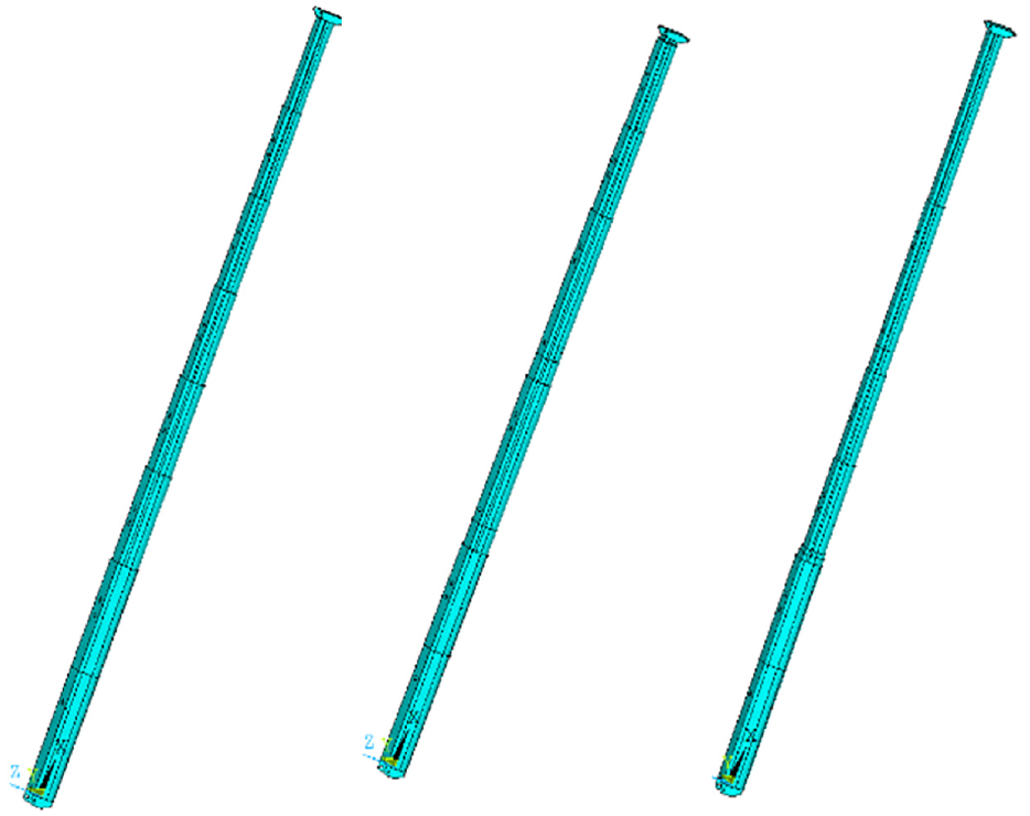
The ANSYS model.
Tables 6 and 7 respectively list the displacement values and time consumption of the guide wheel axis center of the arm head in the vertical direction calculated using the method proposed in this paper under different sizes of lifting loads in working conditions 2, 4, and 5, as well as the comparison with the results of ANSYS shell element modeling analysis. From the data in the table, it can be seen that the displacement solution obtained by this method has very little difference from the ANSYS solution. At the same time, when using ANSYS shell element modeling, 82,806 nodes and 82,279 elements are divided, and 496,836 nonlinear equations need to be solved; This article divides the method into 27 nodes, 20 super units, and requires solving 162 nonlinear equations. The implementation of variable step size in the solving process will save the solving time in the linear deformation stage. In addition, programmatic modeling can be achieved with only the size parameters shown in Tables 1 and 2, without the need to repeat the modeling process in ANSYS, providing a reliable model for large-scale and rapid calculation of the lifting performance of mobile cranes. In the analysis of buckling load, it is very important to select the appropriate buckling index to determine the value of the final buckling load. Although the determination of the most accurate instability index depends on the validation and subsequent correction of the specific product test, the theoretical analysis of this paper suggests that the selection of the instability index of 3 is a relatively rational initial choice.
The vertical displacements under different loads of conditions 2, 4, 5 (mm).

The calculation time under different loads of conditions 2, 4, 5 (s).

Unstable load of telescopic arm structure in fully extended state
According to the method proposed in this article, the differential form (68) of the structural balance equation for the load parameters of the telescopic arm under condition 6 of full extension in Table 5 is solved. The unit load increment

The reference points of telescopic boom structure.
Figure 16 shows the variation curve of the reference point displacement with respect to the lifting load, where

The displacements of reference points.
Figure 17 shows the deformation diagram of the structure during the process of searching for an unstable load balance path with a load of 21.36 t. To display it clearly, the displacement is magnified by 5 times. It can be seen that the deformation of the telescopic arm structure is very obvious at this time, with the characteristic of nonlinear large displacement.
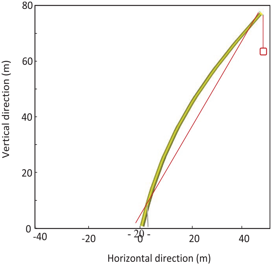
Deformation of telescopic boom under critical load.
It can be seen from the buckling load performance curves of the lower boom of two different telescopic arm combinations that the buckling load curves of different buckling indexes do not change linearly. When the instability index is small, the geometric nonlinear effect of the structure is not obvious, and the buckling load performance curve shows a certain linear effect. As the instability index increases gradually, the nonlinear effect of the curve becomes obvious. With the increase of the length of the telescopic arm, the instability load it can carry also decreases greatly under the same initial attitude Angle. At the same time, the standard telescopic arm belongs to the structure of overhanging cantilever beam. As the working Angle decreases, its axial force also gradually decreases under the same load. From the Angle of Euler instability, it can be concluded that the instability load gradually increases, which also verifies the accuracy of the calculation example.
Conclusions
By integrating the modeling concept of multi-flexible system dynamics into the modeling process of geometric nonlinearity of structures, this paper extends the modeling method of geometric nonlinearity analysis of slender multi-flexible structures. Based on the theory of multi-flexible body modeling, the slender multi-flexible body beam structure is divided into several substructures, and the following connected basis is established for each substructure. On this basis, the deformation of the substructure is decomposed into the rigid motion of the connected base and the elastic deformation relative to the connected base. Thus, an application condition of calculating the deformation virtual power of beam structures with large rotation is established by using the linear strain of traditional beam elements. Specifically, for conventional box-beam structures, the proposed method can reduce the degree of freedom to less than 30% of the original degree of freedom.
Based on the characteristics of the telescopic boom structure of mobile cranes, this paper proposes a method for modeling the telescopic boom super element and quickly searching for the critical unstable load. The method has the following characteristics: (1) considering the thickness change of the web plate, selecting appropriate boundary nodes to establish a substructure, condensing internal degrees of freedom, and obtaining a two node super element that can be used to describe geometric nonlinear effects; (2) The parallel constraint relationship equation, boundary conditions, and additional node forces between adjacent arm nodes were given, and the nonlinear balance equation and corresponding tangent stiffness matrix of the structure with load control parameters were derived; (3) Transforming the balance equation into its differential form, combined with existing numerical methods of differential equations, a fast way to calculate the deformation path and unstable load of the telescopic arm structure is obtained. The accuracy of the method and its advantages in programing and computational efficiency were verified through numerical examples.
In order to accurately calculate the instability load of slender and flexible structures, a new solution method is proposed on the basis of considering the specific mechanical characteristics of the structures, that is, the unknown external instability load is expressed as the combination of load control parameters and unit load increment, and the derivative of load control parameters is obtained through the system balance equation. The path tracking problem which traditionally depends on incremental iterative solution is transformed into an initial value problem for solving ordinary differential equations (ODE).
Footnotes
Handling Editor: Aarthy Esakkiappan
Declaration of conflicting interests
The author(s) declared no potential conflicts of interest with respect to the research, authorship, and/or publication of this article.
Funding
The author(s) disclosed receipt of the following financial support for the research, authorship, and/or publication of this article: This work has been supported by the National Natural Science Foundation of China (Grant No. 11872137).