
Abstract
This article investigates the elastic compound buckling behavior of latticed columns with three lacing systems under two boundary conditions. Valid numerical method named SEM, that conducts buckling analysis using strain energy of bars and potential energy of chords, was built to address flexural, torsional, and flexural–torsional buckling loads along with their overall and local buckling deformations. Eurocode 3 and finite element software ABAQUS were used to validate the auxiliary of SEM. Through the research on X-lacing, E-lacing, and K-lacing latticed columns under two boundary conditions, the rigidity of bars was found to exceed a threshold value affecting the linear buckling load. When the cross-sectional area of lacing bars tends to 0 or threshold value, Eurocode 3 guidelines were imprecise in forecasting the linear buckling load. Eccentricity and geometric imperfections would decrease the buckling capacity of built-up columns substantially. The K-lacing columns respond more sensitively on local imperfections than the X-lacing and E-lacing columns under simply supported condition. However, for the columns under cantilever state, local imperfections have no significant impact for the three lacing columns. In addition, the numerical results of nonlinear buckling load and equilibrium path from SEM considering geometric imperfections are close to the output of finite element method, validating the accuracy of SEM.
Keywords
Introduction
Built-up columns are widely used in steel buildings and bridges. There mainly exist three types of built-up columns in structural engineering. One is the channel column strengthened by batten plates connecting with two flanges at the open side (Figure 1(a)). The other two are latticed columns with several chords connected by battens or lacing bars (Figure 1(b) and (c)). The battens or bars help to reduce the effective length of columns and enhance the ability of resistance on both the global and local buckling. The difference between them lies in the influence on the shear rigidity and the critical buckling load of columns.

Built-up columns: (a) battened channel columns,(b) battened columns with two chords, and (c) laced columns with two chords.
The failure modes, for laced columns, include flexural buckling, torsional buckling, flexural–torsional buckling, and distortional buckling. Extended research has been done on the bending flexural buckling problems along the virtual axis of columns (flexural buckling around the real axis was assumed to coincide with the solid columns). The main issues focus on the influence of shear deformation of lacing bars on the columns’ buckling and the interaction between the global and local buckling modes. The shear effect on columns’ buckling, first proposed by Engesser, 1 was analyzed by Gjelsvik, 2 Timoshenko and Gere, 3 Uhlman and Ramn, 4 and then introduced by Eurocode 3. 5 The battens or lacing bars were assumed to be a continuous web behaving as a shear panel. The interaction between global and local buckling of built-up columns was investigated by Koiter and Kuiken, 6 Svensson and Kragerup, 7 Bazant and Cedolin, 8 and Duan et al. 9 The buckling failure modes of chords between adjacent lacing joints were assumed to simple supports braced by lacing bars, with the shape functions of sinusoid in accordance with Euler beam. In recent study, the two issues were combined effectively using numerical analysis methods. Kalochairetis and Gantes 10 investigated the collapse load of I-section-laced columns by replacing the effective bending rigidity by a reduced value. The initial imperfections of global and local columns were considered to reduce heavy computational work for practical engineering. Then, transverse loads and arbitrary supports of laced columns were studied in Gantes and Kalochairetis. 11 Approximate second-order analysis of imperfect Timoshenko member considering the above two issues was conducted for different boundary and load conditions of I-section-laced columns.
Torsional buckling and torsional–flexural buckling modes of built-up columns were concerned in few studies. The Euler elastic stability of pure flexural and twisting buckling was calculated in Razdolsky12–15 using statically indeterminate method. The study showed the pure flexural buckling always preceded pure twisting buckling for I-section-laced columns, and Eurocode 3 (EC3) might get unsafe conclusions. The flexural–torsional buckling of evenly battened columns was analyzed theoretically by Wang 16 using total potential energy equation solved by Rayleigh–Ritz method. Unevenly battened channel columns were studied by Ren et al. 17 using piecewise cubic Hermit interpolation (PCHI) to express the rotational displacement function during flexural–torsional buckling deformations. It was found that flexural–torsional buckling was more likely to happen than pure flexural buckling for channel-section columns, which was affected by geometric characteristics and eccentricity. In addition, structural potential energy principle with Rayleigh–Ritz method was widely cited to solve nonlinear buckling modes.18–20 Andrade et al. 21 investigated in detail the effect of restraints stiffness, restraints types, and its interplay on the lateral–torsional buckling behavior of discretely restrained tapered beams. Some important conclusions for restraint characteristic were obtained, such as rigid restraint at the tip promoted the critical load of a cantilever and the distance between the rotation centers of the cross section is the main factor in increasing the buckling strength for translational restraint.
Experimental efforts were conducted for limited types of built-up columns. Battened columns with dimension parameters of batten spacing and chords distance were performed in Hashemi and Jafari22,23 to evaluate the accuracy of the methods proposed in previous studies. The results showed the average value of Ayrton–Perry and ultimate strength curve methods led to best prediction of the column compressive strength, and the Engesser equation gave the least accurate results. Battened columns with four identical chords were conducted in Aghoury et al.,24,25 accounting for both geometric and material nonlinearities. Both experimental and finite element models were used to investigate the interaction between slender outstanding width–thickness ratios, overall angle slenderness, and overall column slenderness on the strength of columns. More recently, Z-laced built-up columns with two chords were studied in Kalochairetis et al. 26 to consider the effect of initial geometric imperfections and thermally induced residual stresses. Battened built-up columns (buckling-restrained brace (BRB)) were conducted in Guo et al. 27 to investigate buckling modes and their buckling loads. All the results from the experiments showed a very good agreement with finite element method.
Recently, the buckling behavior of built-up columns under dynamic loads had been studied. Mirtaheri et al. 28 investigated the global and local buckling behavior of restrained brace under earthquake load. The research results acquired from finite element method and experiments show the flexural stiffness of restraining member has a significant influence on the global buckling behavior of brace. Jiang et al. 29 studied the effect of the axial and rotational restraint stiffness on dynamic buckling performance of columns under fire. The rotational restraint stiffness was found to be relatively insensitive to rotational stiffness ratio beyond a threshold value. Some researchers introduced the optimization issue based on the buckling constraint conditions. Ozbasaran and Yilmaz 30 conducted shape optimization for tapered I-beams based on constraints of lateral–torsional buckling, deflection, and stress. Schmidt and Curbach 31 investigated the optimal cross section of concrete columns to increase the buckling capacity.
Yet, the solution and analysis of compound buckling modes for laced columns were rarely seen in the published literature. In this work, the deformations of compound buckling modes containing five low-order buckling modes were expressed by the superposition of global and local shape functions. Then, the total potential energy of chords was integrated and solved to get compound buckling loads. The five basic low-order buckling modes in Figure 3, obtained by linear buckling analysis, consist of flexural and torsional buckling deformations in local and global columns. The critical buckling mode of laced columns was found to transform among compound buckling modes, which were determined by geometric characteristics, type and size of lacings, eccentricity, and initial imperfections.
Three typical laced columns (X-lacing, K-lacing, and E-lacing) under two boundary conditions (simple supports and cantilever) were discussed in the article. Parametric studies were performed to consider the effect of eccentricity and initial geometric imperfections on critical buckling load. Design parameters were cross-sectional area
Structural model
A standardized latticed columns consisting of channel chords and lacing bars are plotted in Figure 2. As shown in the figure, O, C1, and C2 are the cross-sectional centroid of whole columns, chord 1, and 2, respectively. S1 and S2 are the shear centers of two channel chords. Functions

Latticed columns with lacing system: (a) measurements of cross-sectional A-A profile; (b) latticed columns; (c) twisting and bending deformations of chord 2 section, the original and buckling deformation position of section B-B are shown in dashed and solid lines, respectively; and (d) the braced loads produced by lacing bars at joints connecting chords and bars.
The structural material and characteristics conform to general standards in structural engineering. That means, (1) chords and lacing bars are made of homogeneous, isotropic, and linearly elastic material with Young’s modulus E and shears modulus G; (2) all lacing bars have identical cross sections with area
To analyze the buckling failure modes of latticed columns with different lacing bars systems, the following important assumptions are set:
The cross sections of each chord remain a plane, and shear strain in the middle plane is zero before and after buckling deformations (two basic assumptions, Vlasov 32 ). Besides, the shear deformations, residual stresses, and distortional buckling of chords are neglected.
The lateral bending buckling of latticed column around the real axis (Y-axis) corresponds with the solid-web columns (EC3). As shown in Figure 2(d), that means the lacing bars provide no lateral braced load along the Y-axis.
Referring to AG Razdolsky,
14
only axial rigidity
The braced loads produced by lacing bars are deemed to be constant before and after buckling deformations.
Based on above hypothesis, the critical buckling load relating to low-order buckling failure modes in Figure 3 were calculated with numeral analysis method SEM separately considering the strain energy of bars and total potential energy of chords.

Low-order buckling failure modes of simply supported latticed columns obtained by finite element analysis: (a) global bending buckling mode in the X-direction, (b) local bending buckling mode in the X-direction, (c) global twisting buckling mode around shear center, (d) local twisting buckling mode around shear center, and (e) global bending buckling mode in the Y-direction.
Boundary conditions and shape functions
Two boundary conditions with simple supports (1) and cantilever conditions (2) are considered for latticed columns. The simply supported columns are restrained with two ends simply supported, while cantilever columns with one end fixed (warping deformation restrained) and the other end free. The global buckling displacements of latticed columns coincide with Euler columns under the two boundary conditions, while the local buckling deformations of columns were considered all along with simple supports between adjacent lacing joints.
Corresponding displacement functions of global and local buckling are listed in Table 1. The selection of shape functions aims to express corresponding buckling deformations exactly. In instance of simply supported boundary, the low-order buckling deformations in Figure 3 agree nicely with the corresponding shape functions in Table 1.
Boundary conditions of latticed columns and corresponding displacement functions (m = number of sub-elements in length L).

GM: global buckling mode; LM: local buckling mode.
In this article, the shape functions of compound buckling were selected to consider all the low-order buckling failure modes. Based on assumption 3, the lacing bars only provide lateral braced loads around the X-axis and twisting moments for chords. Thus, for all boundary conditions, the shape functions


The strain energy of lacing bars system
According to assumptions 3 and 4, the lacing bars were considered to be separately deformable bodies with axial and bending deformation outside the lattice plane. Thus, the strain energy of lacing bars system consists of its own axial and bending strain energy.
The lateral displacements of chord i in connected joints k along the virtual axis Xi on the front and back planes are
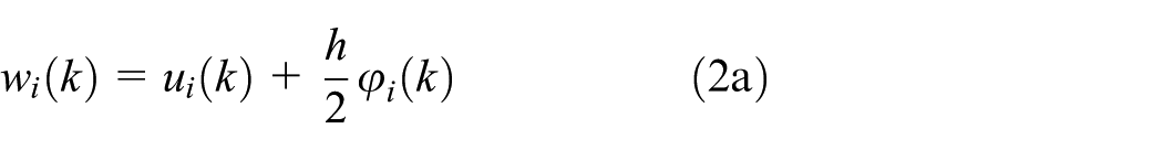

The relative values of lateral displacements of chords induced lateral braced loads


where
For the three types of lacing bars systems shown in Figure 4, the lacing bars can be classified to transverse bars and diagonal bars. Thus, the axial strain energy of lacing bars counting front and back latticed planes is divided to the transverse bars in equation (4a) and diagonal bars in equation (4b)


Three typical lacing bars systems: (a) K-lacing, (b) X-lacing, and (c) E-lacing.
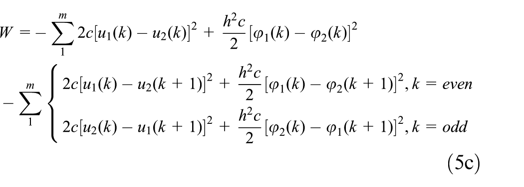
The total strain energy of the three typical lacings systems in Figure 4 was calculated according to equations (2)–(4). The results were shown in equation (5). For X-lacing type

For K-lacing type

For E-lacing type
Buckling analysis of chords using energy method with strain energy of lacing bars (SEM)
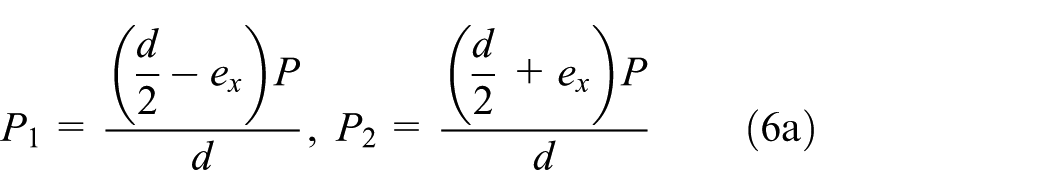
Subjected to an eccentric axial compression load P offsetting the center

where

where
And,

W is the load potential energy of chords caused by the total strain energy of lacing bars system which has been derived in equations (5a)–(5c).
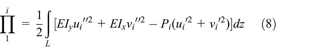
An X-lacing type of laced columns with two ends simply supported was selected to illustrate the computational process of SEM in detail. The total potential function

And

And

In equation (10),

K 1 and K2 are the influence coefficients of sub-elements spacing in the length L

Applying the principle of minimum potential energy, the non-zero solution of buckling loads P can be obtained by setting the first-order derivative of total potential energy
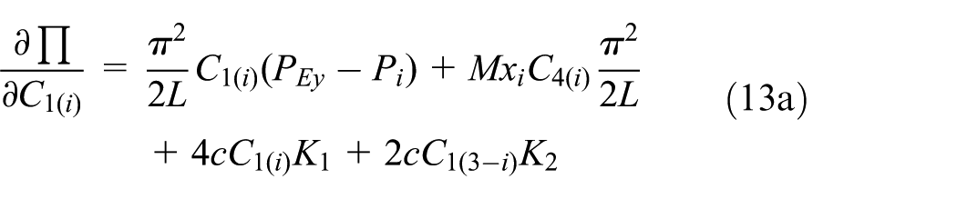
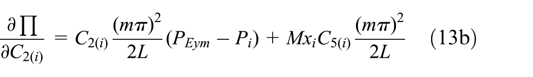


Equation (13) can be expressed in the form of matrix by

The solutions of equation (15) are buckling loads relating to all possible buckling failure modes. To compare the compound buckling loads with Euler critical loads, a parabolic function

Comparison with EC3 and FEM
The existing specification EC35 and Tong and Chen
33
provided detailed expressions for global and local buckling loads of compressive latticed columns with several uniform types of lacing bars. The global bending buckling loads
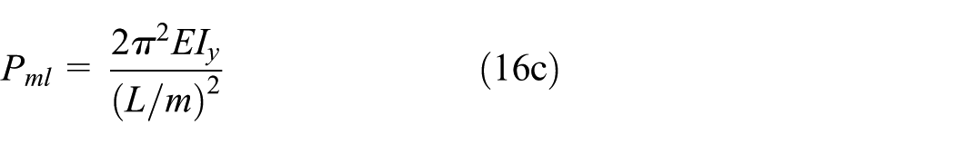
where
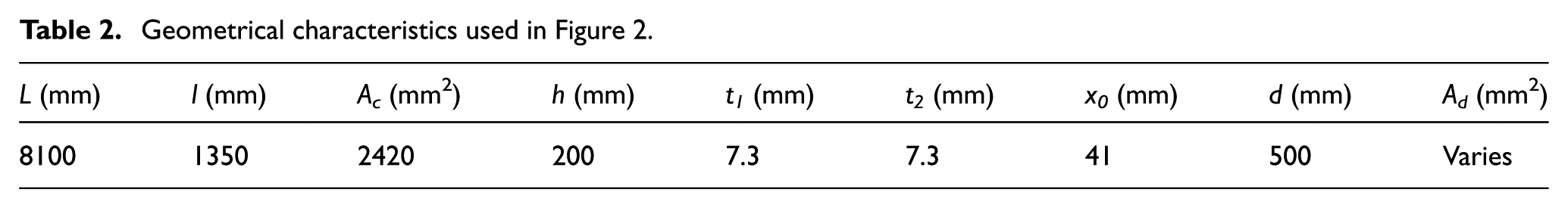
Three types of lacing bars system in Figure 4 are selected to validate the correctness of SEM proposed in this article. For all types, the columns are made of structural steel Q235 (elastic modulus E = 210 MPa and shear modulus G = 79 MPa). The chords have bending moments of inertia
Geometrical characteristics used in Figure 2.
Three lacing bars systems under two boundary conditions have been analyzed, corresponding to the varying values of non-dimensional ratio
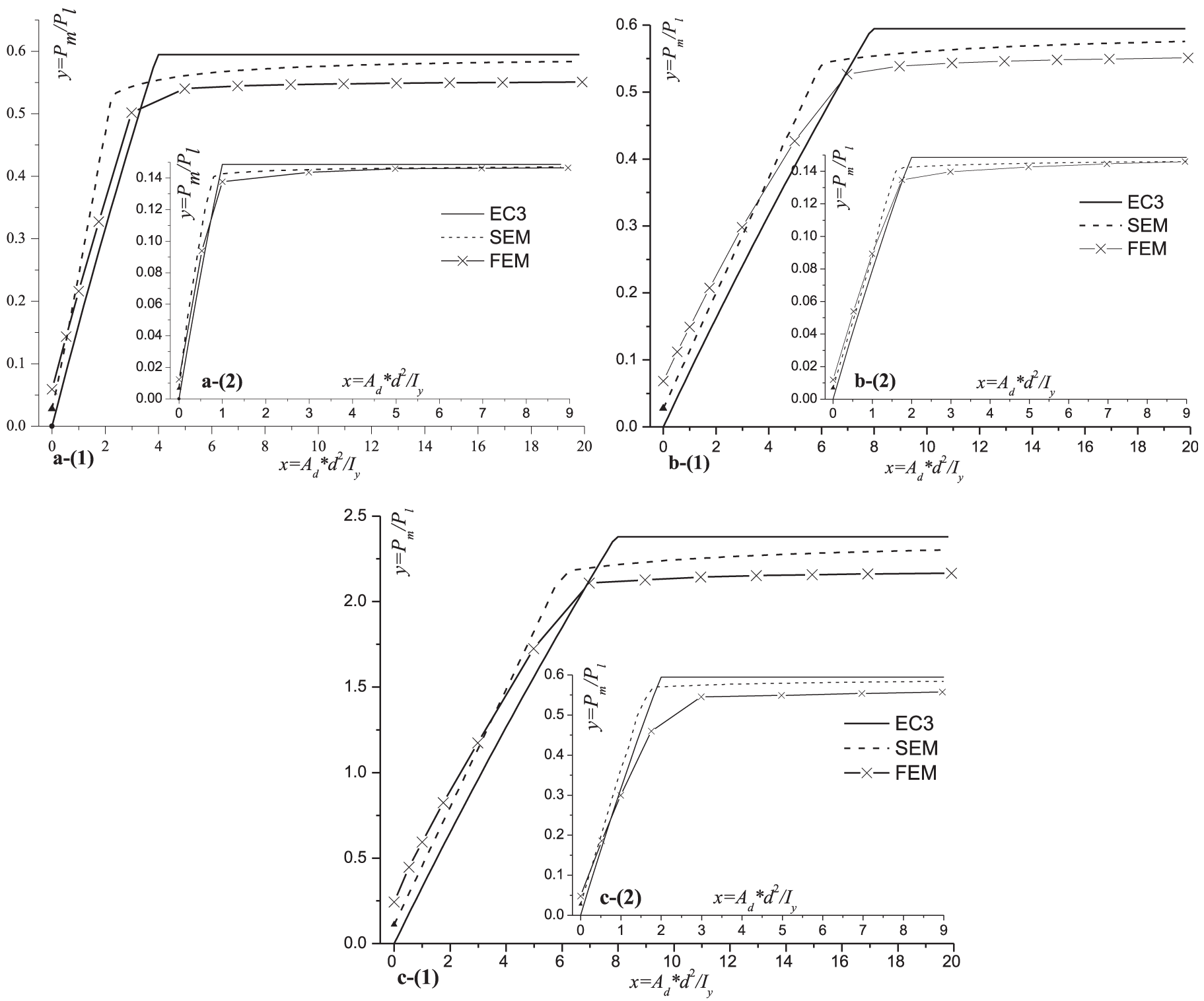
Relationship between bars’ cross-sectional area
As shown in Figure 5(a)–(c), the forecasts of elastic critical buckling load from SEM have a good match with EC3 and FEM for the three typical lacing bars systems. When the cross-sectional area
Compared with SEM and FEM, EC3 method is found to have two questions in forecasting critical buckling load of latticed columns. The calculating results are both inaccurate, whether cross-sectional areas of lacing bars
Influence of eccentric compressive load
As shown in equation (6a) and (6b), the eccentricity
An X-lacing latticed column under simply supported boundary was selected to illustrate the influence of eccentric axial compression the critical buckling load. Three different sizes of lacing bars with cross-sectional area

Critical buckling load
When the eccentricity
For example, in the case of
Comparing Figure 6(a) and (b), when the cross-sectional area

The variable curves between the eccentricity

Relationship between the eccentricity
Influence of initial geometric imperfections
There are always initial geometric imperfections in built-up columns that reduce their buckling ability of resisting external loads. In the previous research works of laced columns,10,11,25 the shapes of initial lateral imperfections in global and local locations were chosen to be consistent with global and local flexural buckling modes (Figure 3(a), (b), and (e)), respectively. Similarly, the initial twisting imperfections should also coincide with the shapes of torsional buckling modes (Figure 3(c) and (d)).
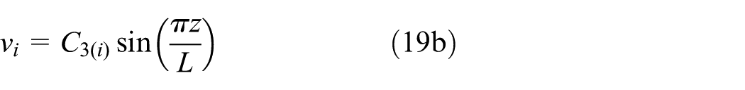
Also, an X-lacing laced column under simply supported boundary was chosen to discuss the influence of initial imperfections on critical buckling load. Namely, the maximum global and local imperfections Xg, Xl are L/500 and l/500, respectively. So, the imperfections of chords can be expressed in equation (18)
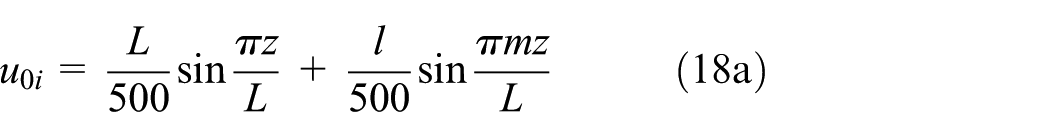


In theory of stability of structure, 35 the precise solution of nonlinear equilibrium paths is the convergence of all the linear buckling modes. But in reality, only finite modes can be guaranteed due to calculated problem of the nonlinearity. In equation (19), the five low-order modes were considered to get approximate nonlinear solutions, compared with nonlinear post-buckling analysis of FEM

where

Torsional–flexural strain energy and its load potential energy

The strain potential energy of lacings system (unchanged)

Similar solution method was applied to acquire the load–displacement curves of nonlinear deformation with initial imperfections. The numerical results of SEM and FEM for X-lacing, E-lacing, and K-lacing columns under two boundary conditions are all plotted in Figures 8–10, respectively. It can be observed that, for all the lacing types and boundary conditions, the critical buckling loads reduce largely due to the initial imperfections existing. In addition, linear buckling analysis always provides an upper value in forecasting critical buckling loads of laced columns, which are in accordance with the theory of Bazant and Cedolin. 35

Load–displacement curve of elastic equilibrium paths for X-lacing columns under (1) simple supports and (2) cantilever state: (a) Ad = 10 mm2, (b) Ad = 15 mm2, (c) Ad = 20 mm2, (d) Ad = 25 mm2, and (e) Ad = 30 mm2.

Load–displacement curve of elastic equilibrium paths for E-lacing columns under (1) simple supports and (2) cantilever state: (a) Ad = 10 mm2, (b) Ad = 15 mm2, (c) Ad = 20 mm2, (d) Ad = 25 mm2, and (e) Ad = 30 mm2.

Load–displacement curve of elastic equilibrium paths for K-lacing columns under (1) simple supports and (2) cantilever state: (a) Ad = 10 mm2, (b) Ad = 15 mm2, (c) Ad = 20 mm2, (d) Ad = 25 mm2, and (e) Ad = 30 mm2.
It can also observed that, compared with cantilever state, the three lacing columns under simple supports have a more obvious response for local imperfections. The local imperfections have almost no impact on the critical load of the three lacing columns under cantilever state. However, the K-lacing columns under simply supported conditions respond more sensitively on local imperfection than the X-lacing and E-lacing columns when the cross-sectional area of bars ranges from 10 to 20 mm2. Once the rigidity of bars exceed to the threshold value, such as Ad = 25 and 30 mm2 in Figure 10, the local imperfections would no longer affect the critical loads intuitively.
Although not deeper discussion about the threshold braced stiffness, as Figure 7, in the procedure of nonlinear buckling with imperfections, the threshold braced stiffness Ah of lacing bars still exists. Note that the critical load of the three lacing columns increases in smaller and smaller values, when the cross-sectional area Ad of bars varies from 10 to 30 mm2 in Figures 8–10.
Example verification with shell-link element models of FEM
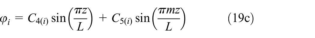
Three finite element models for X-lacing, E-lacing, and K-lacing built-up columns are established in Figure 11 to verify the numerical results of proposed SEM in this article. The chords are modeled with four-node shell element, while the lacing bars two-node link element by commercial software ABAQUS. All freedoms of lacing bars were coupled to the corresponding nodes of chords. To avoid the local warping at the columns ends, the master–slave nodes technique was used in FEM to simulate loading and boundary conditions more realistically as shown in Figure 11(b). Both the analytical modules of linear buckling analysis and nonlinear post-buckling with initial imperfections were performed to validate the relationship between critical buckling loads with corresponding design parameters in the article.
Modeling procedures for X-lacing, E-lacing, and K-lacing columns using ABAQUS: (a) interaction between chords and lacing bars; (b) boundary and loading conditions under simple supports and cantilever state.
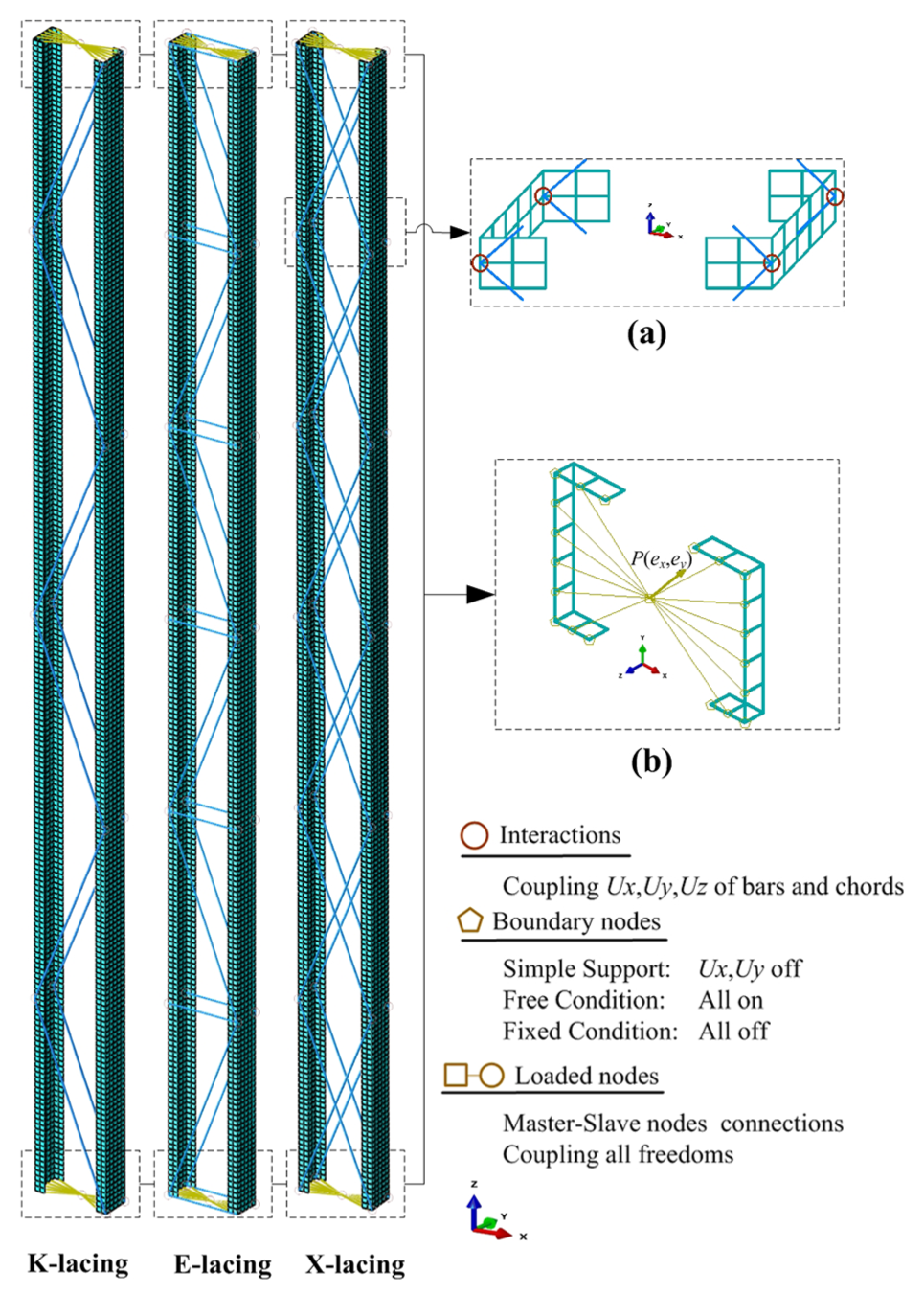
From the equilibrium paths of nonlinear post-buckling analysis in Figure 12, it can be observed that the nonlinear deformations mainly consist of global bending buckling and global twisting buckling of each chord. Local bending and twisting buckling are less important than the global buckling in the post-buckling path for the analytical model.
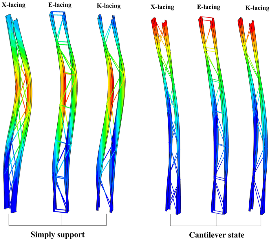
Equilibrium path of the three lacing columns under two boundary conditions of simple supports and cantilever state acquired through nonlinear post-buckling analysis of ABAQUS (Ad = 30 mm2).
To better compare the results of FEM and SEM, equally spaced test points A–F were selected from chord 1 of X-lacing, E-lacing, and K-lacing columns (under simple supports and cantilever state) as shown in Figure 13. The nonlinear equilibrium paths of SEM are the superposition of global bending and twisting buckling functions, which are very close to the results of FEM. It validates that the SEM is very concise and accurate in calculating the linear buckling and nonlinear buckling capacity of latticed columns.

Comparing the equilibrium path of method SEM with FEM (Ad = 30 mm2): (a) X-lacing built-up columns, (b) E-lacing built-up columns, and (c) K-lacing built-up columns.
Summary and conclusion
Considering total potential energy of bars and chords individually, the compound buckling loads of latticed columns were discussed with three types of lacings under two boundary conditions. The present analysis highlights the critical buckling load affected by design parameters (size of bars, eccentricity, and initial geometric imperfections). The threshold stiffness EAh was calculated on conditions of eccentricity in linear buckling analysis. Based on EC3, FEM, SEM, and their output, the following main conclusions were drawn:
The calculation of elastic buckling loads from EC3 has a shortcoming. Whether the cross-sectional area of bars Ad tends to 0 or Ah, the forecasting of linear buckling load from EC3 was inaccurate. When Ad tends to 0, the minimum buckling load tends to 0, unconfirmed to the property of engineering structure. When Ad tends to Ah, the minimum buckling load from EC3 was about 20% higher than that of FEM, getting unsafe result for laced columns.
Through the research on linear buckling load of X-lacing, E-lacing, and K-lacing columns under two boundary conditions, the eccentricity of compressive load would obviously decrease the buckling capacity of built-up columns, especially for bidirectional eccentricity ex, ey. And, the cross-sectional area of bars has a threshold value Ah. The elastic critical buckling load Pm would almost not increase after the cross-sectional areas of lacing bars Ad exceed to Ah. The threshold stiffness was affected by eccentricity ex, ey and initial geometric imperfection Xg, Xl, besides the structural characteristics.
Based on the nonlinear buckling load considering geometric imperfections, the existing of initial imperfections Xg and Xl would reduce the critical buckling load of all the lacing columns. But, the local imperfections Xl have almost no impact on the critical load of the three lacing columns under cantilever state. However, the K-lacing columns under simple supports respond more sensitively on local imperfection than the X-lacing and E-lacing columns when the cross-sectional area of bars varied below the threshold value.
Based on the nonlinear buckling deformation using methods SEM and FEM, the equilibrium paths of laced columns were found to consist of the low-order linear buckling modes. The proposed method SEM, expressing the nonlinear buckling deformation by the superposition low-order mode functions, has a reliable accuracy as FEM in forecasting the nonlinear buckling load and deformation. However, the method SEM is more simple and formulaic than FEM.
Footnotes
Appendix 1
Appendix 2
Handling Editor: James Baldwin
Declaration of conflicting interests
The author(s) declared no potential conflicts of interest with respect to the research, authorship, and/or publication of this article.
Funding
The author(s) disclosed receipt of the following financial support for the research, authorship, and/or publication of this article: This work was supported by the National Natural Science Foundation of China (NSFC) under grant numbers 51675450 (working) and 51175442 (finished).