
Abstract
The load-sensing electro-hydrostatic actuator (LS-EHA) allows to reduce the thermal output and enhance the dynamic characteristics of the more electric aircraft (MEA). In addition, the forecasting of the LS-EHA is crucial for its efficient functioning. This study proposes a novel model for the analysis of overturning and wear characterization of the slipper, while focusing on the partial abrasion. The transient thermoelastic hydrodynamic (TEHD) lubricating analysis of the slipper pair is solved by an analytical model along with the finite difference method. In the proposed partial abrasion model, the non-uniformity of the oil film thickness and the partial abrasion contour for the slipper bottom surface are considered through the discrete friction area approach in order to reach a higher precision. Afterward, the overturning behavior characteristics of the slipper and the variation law in its overturning behavior under different rotation speeds, load delivery pressures, and swashplate angles are analyzed. The obtained results demonstrate that the lubricating oil film field is unevenly distributed, and the overturning behavior of the slipper has certain variable load characteristics. Finally, the effectiveness and precision of the proposed partial abrasion model are validated through comparative simulation experiments and analysis.
Introduction
In the development of aircraft hydraulic systems, the use of composite materials is an important direction. 1 Employing composites in the design of hydraulic cylinders can significantly reduce weight, and advanced research has been conducted in this area. However, large-scale production of composite material cylinders still faces challenges. Additionally, in modern aircraft hydraulic systems, increasing the pressure can enhance the energy flow density, but this also raises the risk of damage to the hydraulic lines. 2 Due to these issues, new approaches are being explored. Therefore, the more electric aircraft (MEA) has emerged and has become an inevitable choice for the upcoming generation of aircrafts. In the MEA, the power system is used to partially replace the traditional hydraulic, pneumatic, and mechanical systems, which allows to reduce the weight and the emission, and to improve the reliability. The electro-hydrostatic actuator (EHA) is a crucial technology within the MEA power-by-wire actuation system. It has been used on the A-380 new passenger aircraft and the F-35 military aircraft.3,4 The working principle is summarized as follows: the motor drives the high-speed hydraulic pump to rotate generating high-pressure oil flowing into the cylinder, and the piston rod overcomes the load under the action of pressure difference to push the aircraft rudder (e.g. the elevator or the aileron) to deflect. However, at present, the traditional EHA systems are only used as backup because of their excessive heat generation problem, which has not been solved yet. In recent years, a novel load sensing electro-hydrostatic actuation (LS-EHA) system has been proposed.5,6 This system has less heat generation and good dynamic characteristics, as shown in Figure 1. When the LS-EHA operates under high load and low speed conditions, the pump displacement is reduced by decreasing the swashplate angle, while the motor speed is increased to maintain stable actuator output. This approach can effectively reduce the motor’s output torque, which is influenced by the pump displacement. Additionally, since the armature current is directly proportional to the motor’s output torque, the armature current will also decrease as the output torque is reduced. 7 As a result, various losses in the motor can be reduced, and the resulting heat will also decrease. 8 Therefore, it represents the development trend of the future aircraft actuation systems.
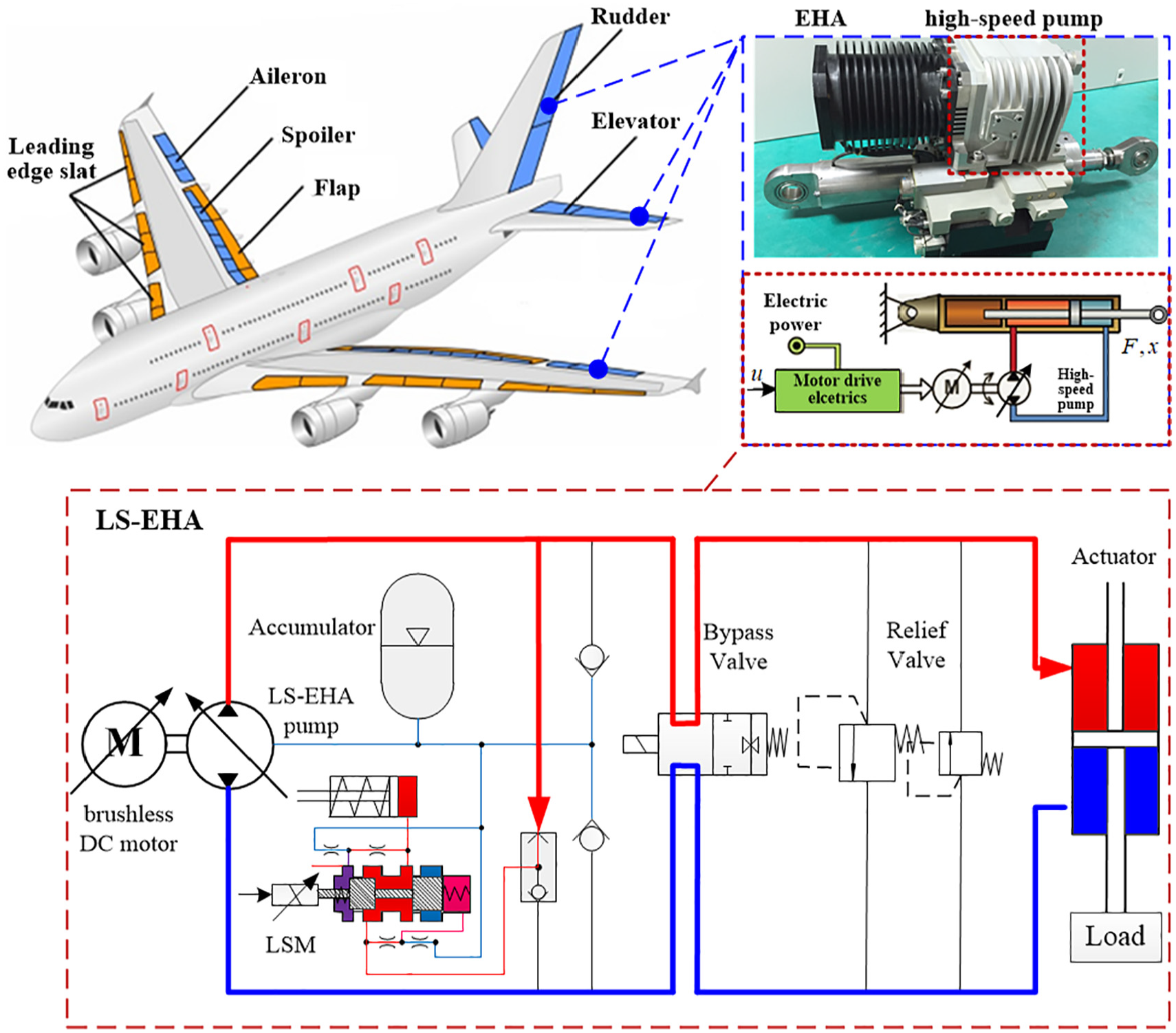
Schematic of the LS-EHA system and the high-speed pump used in LS-EHA.
The EHA high-speed pump is a core component of the LS-EHA. Since the introduction of the axial piston pump featuring a slipper/swashplate con-figuration in the 1950s, many structural optimization designs have been developed. These designs significantly enhanced the working pressure, speed, and displacement of the hydraulic piston pump. However, these studies mainly aim at improving the pump performance, while those tackling the failure mechanism and performance degradation model, especially for the high-speed aviation hydraulic pump, are still few. Analyzing the mechanism of the failure of the high-speed pump in the LS-EHA is crucial for ensuring its safety services. The high-speed pump of the LS-EHA serves as a hydraulic power source, which converts the mechanical energy into high-pressure hydraulic energy. It is crucial in ensuring the reliability and lifespan of the power-by-wire hydraulic system in multi-electric aircraft. Compared with the hydraulic system traditional pump, the EHA pump has smaller volume and higher power mass ratio, which is due to its higher rotating speed, greater working pressure, and smaller displacement. To meet the flight load requirements of the MEA, it usually uses a high rotational speed (greater than 10,000 rpm). An EHA pump able to rotate at a velocity of 15,000 rpm is proposed in Refs.9,10 Although the high speed and pressure led to high power density, they resulted in serious problems to the LS-EHA aviation pump. In particular, the wear and reduction in the lifespan of the friction pair is its most critical issue.11,12 In addition, under conditions of high pressure and velocity, the micro pressure deformation and thermal deformation of the friction pair interface are severe, which can easily cause the wear, leakage, and even failure of the pump, making it difficult to meet the requirements of long service life and low probability of flight failure. Wear is one of the main causes of mechanical system failure. Thus, it is often accompanied by lubrication. Investigating the microscopic lubrication and wear properties serves as a crucial aspect in the prediction of the extent of EHA pump failure for preventive maintenance purposes. 13
Many studies have been conducted on the lubrication and wear of friction pairs in aviation hydraulic pumps. For instance, Ivantysynova14–18 deduced that the transient effect of the slipper deformation can generate transient deformation extrusion pressure, and the change of the pressure field significantly affects the overall oil film thickness. Bartel et al. 19 proposed a computational model suitable for preliminary design and evaluation of the transient friction and wear characteristics of sliding bearings under mixed friction conditions. For predetermined time steps, the model can calculate local wear along the circumference and width directions. Bergada et al.20,21 proposed a model for simulating fluid flow using computational methods in order to predict the leakage. They deduced that the main cause of fluid loss in the piston pump is the slipper/swashplate pair or the cylinder/valve plate pair. Xu et al.22–24 conducted theoretical and empirical studies on the lubrication properties of the core friction pairs of the EHA pump by respectively adopting simulation program calculation and building test benches. These studies allowed them to obtain key parameters such as the oil film thickness and rotation speed. The leakage and friction moment of the EHA high-speed pump friction pair have also been studied,25,26 while considering the overturning behavior of the slipper as the main cause of partial abrasion. In the study presented in Ref., 27 a transient mixed thermoelastic hydrodynamic (MTEHD) lubrication model was developed by coupling factors such as contact, elastic deformation, temperature increase, and viscosity change caused by heat transfer on the rough surface. This al-lowed to reveal the thermal-fluid-structural interaction characteristics at the contact inter-face. The authors of Ref. 28 studied a mixed lubricating model of slipper pair for early wear while taking into consideration the micro-surface changes during wear. The overturning of the axial piston pump slipper as well as its collision and wear behavior with the swashplate were analyzed in Ref. 29 Long et al. 30 proposed a thermal-fluid-solid multifield coupling simulation model based on cumulative wear damage, which can be used to study the dynamic characteristics of the oil film under the cumulative effects of wear on the slipper.
Many studies have been conducted on the pump wear properties and their influence on the pump performance through numerical simulations 31 and experiments.32,33 The volumetric efficiency of the pump is crucial to its performance. As the pump operates, an increase in pressure leads to greater deformation of the pump components and an enlargement of the clearance dimensions within the pump. This results in increased internal leakage and reduced volumetric efficiency. 34 Additionally, wear of internal hydraulic pump components also contributes to a decrease in volumetric efficiency. At present, it is generally believed that abrasion is the main cause of wear in the pump, 35 especially when a significant difference between the hardness of the two materials exist. Ma et al. 36 proposed an abrasive wear model of the piston pump slipper pair and determined the internal factors affecting the slipper wear rate. Nie et al. 37 introduced the theory of frictional wear and cumulative damage into the piston pump for describing its wear characteristics. Lyu et al. 38 combined the load and lubricating parameters of the piston pair into a model adopted for computing the wear volume. A method for predicting the piston pair wear process varying over time has also been proposed. However, com-pared with the ordinary axial piston pump, the LS-EHA commonly experiences complex mixed lubrication conditions during the operation of its high-speed pump, which leads to severe wear characteristics. In practice, under high-speed conditions of EHA, the lubricating oil film is usually non-uniformly distributed. In addition, as the pump displacement of the LS-EHA changes during operation, multivariable changes generate new failure mechanisms. In summary, studies on the wear mechanism of the LS-EHA pump should be further conducted.
This paper studies the high-speed working condition of the LS-EHA high-speed pump. The main reason of malfunction in the high-speed pump is first analyzed to determine the main factor affecting its reliability. A transient thermoelastic hydrodynamic (TEHD) lubricating model of the aviation hydraulic pump is then developed. On this basis, a novel partial abrasion model is proposed, which takes into account the local abrasion characteristics of the slipper and the non-uniform distribution of the lubrication oil film, thereby improving the accuracy of calculating the wear volume of the slipper pair. Moreover, the lubrication failure mechanism of the pump used in the LS-EHA under variable load is also analyzed in this paper.
Failure mode analysis and weak link identification of the LS-EHA pump
Three sets of friction pairs exist in the LS-EHA axial piston pump (Figure 2): the pair formed by the piston and cylinder, the pair consisting of the slipper and swashplate, and the pair involving the cylinder and valve plate. All these friction pairs are characterized by very small clearance and large load. In addition, their performance in the pump directly affects its efficiency, dependability, and longevity. Especially when its working at high speed, it causes many problems such as smaller clearance between friction pairs, alternating heavy load, high-frequency impact, system temperature increase, and leakage problems. Key friction pairs are more prone to friction and wear failure.

Friction and abrasion in crucial frictional components of the high-speed pump.
Under high-speed operating conditions, the most significant change is the increase of the inertia-moment/force and viscous friction force, which significantly affects the slipper overturning and lubrication eccentric wear of the pump. Moreover, certain regions in a high-speed piston pump may experience cavitation. 39 This phenomenon is a dynamic process and can pose certain risks to the piston pump. 40 Therefore, relevant studies are needed, but with a primary focus on the most significant changes. On the one hand, it has been shown by experimental studies on the faulty high-speed pump that the slipper pair is the most serious worn friction pair, as shown in Figure 2. On the other hand, theoretical studies demonstrated that the main cause of leakage in piston pumps is either the slipper pair or the valve plate pair, accounting for more than 94% of the total leakage. 21 Therefore, it is known that the eccentric wear of the slip-per/swashplate pair is the vulnerable factor responsible for the degradation and malfunction of the LS-EHA pump.
In summary, in this study, the slipper pair is considered as the primary vulnerable aspect. That is, the slipper pair partial abrasion results in increasing the leakage of the LS-EHA high-speed pump and the decrease of its volumetric efficiency, which further affects its performance and dependability.
Partial abrasion modeling based on the TEHD lubricating model
In this section, a partial abrasion modeling method of the LS-EHA high-speed pump, using the transient TEHD lubricating model, is proposed. By discretizing the friction area, the proposed model takes into account the oil film overturning characteristics and uneven distribution. The oil film lubricating field and eccentric wear volumes of the slip-per/swashplate pair are constantly updated in the calculation cycle.
Analysis of forces acting on the slipper pair
The pressure solution of the lubricating oil film relies on the analysis of the dynamics of the slipper. The slipper experiences forces and torques, as shown in Figure 3.

Schematic diagram of the forces acting on the LS-EHA pump.
The primary load (
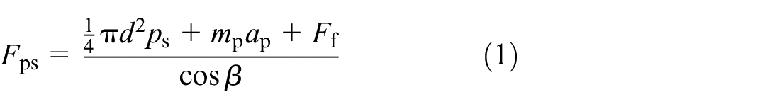
The forces acting on the slipper include the gravity (
The centrifugal force acting on the center of mass of the slipper (

The viscous friction generated on the slipper is given by
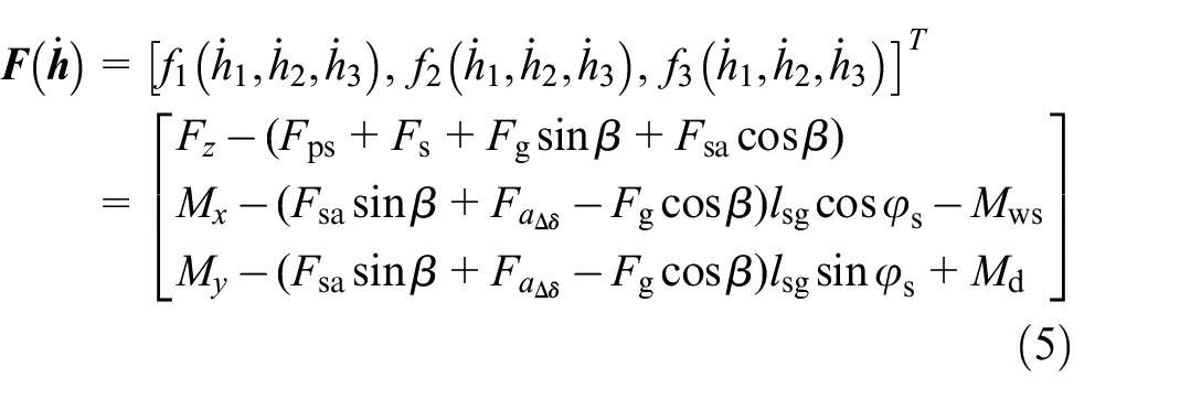
The fluid forces and moments at the slider/swashplate interface are obtained by integrating the pressure distribution:

After considering all the forces and moments that affect the slipper, the dynamic model of partial lubrication for the slipper can be written as:

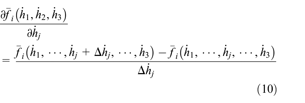
Equation (4) can be expressed in a standard Newton iteration form:
A specific solution is presented in the following algorithm:


where

where:

where


where
If
Theoretical model of the lubricating oil film
The oil film supports the slipper through the hydrodynamic effect. It also provides lubrication. However, wear will occur if the oil film thickness falls below the threshold established based on the surface roughness.
Considering that the lubricating oil film thickness between the slipper and swashplate is usually only of few micrometers, it can be deduced that the flow remains laminar and the fluid behaves as Newtonian fluid. The oil film pressure field can be characterized by the Reynolds equation in cylindrical coordinate form:

where

The transfer of oil from the piston chamber to the oil sump located beneath the slipper occurs through the utilization of throttle orifices present in both the piston and slipper:
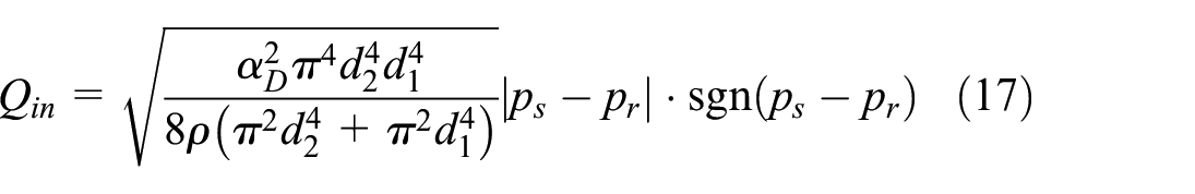
The fluid flow through the lubrication clearance is calculated by integrating the oil velocity along the circumference of the slipper:

where
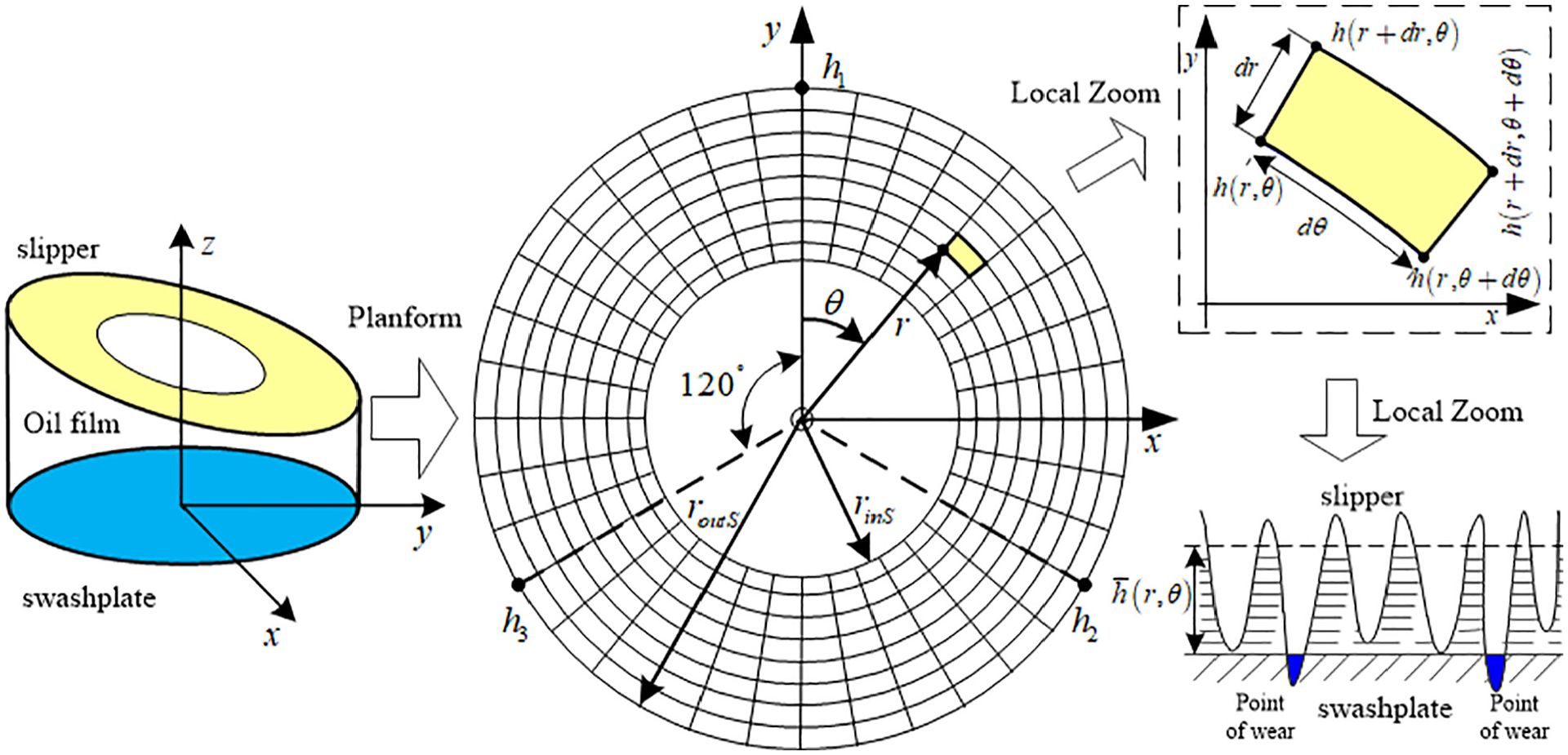
Equation (19) illustrates the expression used to determine the oil film thickness at any given point:

where

Schematic diagram of the thickness field of the oil clearance in the slipper.
The dynamic viscosity changes with the variation of temperature and pressure. The relationship between them is given by:

The negligible heat conduction along the slipper axis is attributed to the oil film thickness, which results in a small impact on the temperature distribution. The oil temperature distribution of the slipper can be determined using the following equation:

To accurately determine the thickness of the oil film lubrication clearance, it is necessary to express the deformation of the slipper caused by the thermal and hydrostatic pressure loads. The thermal expansion of a finite controlled volume is given by:

The slipper elastic deformation (

where
Wear model of the slipper partial abrasion
Under mixed dynamic lubrication conditions, the probability of direct contact between asperities on the contact surface is greatly reduced. This is due to the action of the thermoelastic hydrodynamic lubricating oil film, which greatly reduces the possibility of the generation of adhesive points and adhesive wear. Therefore, this study believes that the main form of wear is the abrasive wear caused by material falling off the rough surface during the friction process. In particular, this wear is produced when the hardness values of the materials of the two friction surfaces are quite different, such as the pair composed of slippers and swashplate within the axial piston pump.35,36
In Figure 5, the oil film in the clearance between the slipper and the swashplate becomes wedge-shaped because of the tilting moment triggered by centrifugal force. However, in the practical implementation of the LS-EHA pump, the complexity of the working condition is further increased due to various factors, such as fluctuating loads and sudden impact loads. The instant countering the overturning effect caused by dynamic pressure cannot be balanced by the overturning moment applied to the slipper. Consequently, the overturning angle will be further increased and the oil film thickness will be decreased. During this process, the outer edge of the slipper may collide with the swashplate, which results in increasing the friction and deteriorating the slipper outer rim. Over the course of time, it will progressively lead to the destruction of the original hydrostatic support structure and to the increase of the leakage flow.

Schematic diagram of the slipper pair: (a) slipper structure and (b) partial abrasion.
It was deduced that the oil film distribution has an irregular pattern, and both the pressure and thermal deformation significantly affect the thickness field of the oil film. Therefore, a description method of unequal distribution of oil film thickness based on friction surface discretization is proposed. This method allows to accurately describe the wear characteristics of the slipper pair discussed in this paper, rather than the parallel surface wear model. When the slipper slides per unit length, the wear volume
where
Note that
The torus between the slipper and swashplate is segmented into circumferential and radial nodes. The entire wedge-shaped oil film is then divided into

Schematic of the slipper oil film thickness discretization.
where
The wear volume within the small grid is given by:
Integrating in the whole solution domain yields the total abrasion volume of the slipper underside:

The slipper path on the swashplate follows an elliptical trajectory. For one cycle of the piston pump cylinder, the stroke of each slipper is given by:

If z slipper components exist in the high-speed aviation hydraulic pump of the LS-EHA, by integrating equation (27) along the slipper rotation trajectory, the total wear volume of all the slipper components for every cycle of cylinder rotation can be expressed as:
Equations (25)–(29) allow to compute the correlation between the partial abrasion volume of the LS-EHA high-speed pump slippers and the pertinent parameters of the friction surface:

The proposed friction surface discretization method takes into consideration the overturning characteristics of the slipper, and describes the partial abrasion characteristics for the its pair. Therefore, it will lead to more accurate results of slipper wear volume loss compared with the traditional parallel wear approach.
The proposed framework
The proposed wear model is validated based on the numerical simulation according to the algorithm shown in Figure 7. The flowchart of the calculation process can be divided into two parts: the first part involves utilizing the TEHD lubricating model to calculate the distribution of the oil film thickness, while the second one focuses on determining the whole wear volume loss of slippers through the partial abrasion wear model. In the TEHD lubricating model, the program should estimate the initial oil film thickness, followed by the first calculation cycle, where the finite difference method is used to determine the pressure and temperature distribution. In the second calculation cycle, the rate of change of the oil film thickness is determined by solving the nonlinear equation using the modified Newton iteration method. Finally, when the rotation angle of the slipper along the swashplate surface changes, the oil film thickness of the slipper pair is updated in the third cycle. In the partial abrasion model, the oil film thickness obtained in the TEHD lubricating model is used to calculate the wear volume in each segment. The slipper total wear volume loss in each motion cycle on the swashplate can be calculated by adding the calculation results obtained by the wear model while varying the slipper rotation angle between 0° and 360°. Finally, the thickness of the oil film and the volume of the slipper eccentric abrasion are updated based on the wear profile algorithm.

Flowchart of the proposed partial abrasion method under the TEHD lubricating model.
The simulation parameters are selected based on the study presented in Ref. 10 (Table 1). When slippers are rotating around the swashplate, the slipper pocket pressure is significantly changed. Thus, the boundary conditions of the TEHD lubricating model will be periodically changed, which results in a transient lubrication and an accumulated wear loss.
Parameters of the LS-EHA high-speed pump.

Validation of the proposed method
The slipper pair oil film thickness field should be first analyzed in order to determine the wear volume. Afterward, under the condition of variable load, the different overturning states of the slipper are discussed. Finally, to evaluate the effectiveness of the proposed model, the partial abrasion volume of the slipper per rotation cycle under different speed/ pressure/ swashplate angle conditions is calculated by simulation.
Lubrication results and discussion
When the slipper starts to move on the inclined plate from ODC (

The slipper oil film thickness distribution in a rotation cycle.

The slipper oil film pressure field distribution in a rotation cycle.
Analysis of the variable load characteristics
It can be deduced from the previous section that the slipper pair is the friction pair with the highest failure rate in the LS-EHA pump. Exploring the dynamics of the overturning posture of the slipper is essential for achieving a load-bearing interface design capable of efficiently supporting high loads with minimal energy consumption. The overturning angle of the slipper oil film can be defined as
Figure 10 shows the overturning angle of the slipper pair oil film under different speeds in the case where the shaft performs one rotation cycle. Within a cycle, when the slipper moves to different angles, the overturning angle is changed, and the angle when moving to the same position gradually increases with the increase of the rotation speed. When passing through the transition zone from high pressure to low pressure, the overturning state of the oil film violently oscillates and reaches an extreme value due to the uneven normal force on the slipper at approximately 220°. Due to the overturning state of the oil film, there is a local reduction in oil film thickness. The partial oil film thickness on the slipper underside surface becomes lower than the height of the asperities, which results in friction and stroke between the slipper and swashplate, leading to partial abrasion behavior and potentially affecting the overall performance and lifespan of the system.

The variable load law of slipper overturning angle with different rotation speeds.
Figure 11 shows variable load laws of the slipper overturning angle with different delivery pressures. The influence of the pressure change on the slipper overturning state is very small near the ODC. However, there is a great difference near the IDC, where it decreases with the pressure increase. It can be deduced that, when the pressure increases, the wear rate decreases. It is important to note that while the change in flip angle has a minimal impact on the wear rate, the reduction in oil film thickness has a more significant effect. When pressure increases and causes the oil film to thin, the wear rate increases, even if the change in flip angle has a relatively minor impact on the wear rate.

The variable load law of slipper overturning angle with different delivery pressures.
Figure 12 shows the periodic variation of the slipper overturning angle when the cylinder rotates one cycle under different swashplate angles. In contrast to the pattern obtained when the delivery pressure changes, the influence of the pump displacement change on the overturning state of slipper pair is small near the IDC. However, it shows a certain difference near the ODC region, especially in the low-pressure region, where the overturning angle gradually decreases with the increase of displacement. This suggests that under low-pressure conditions, increasing pump displacement will reduce the slipper’s flip angle, potentially affecting system performance.

The variable load law of slipper overturning angle with different swashplate angles.
Wear results and analysis
After determining the thickness field of the lubricating oil film, the wear volume loss of the slipper pair can be calculated using the proposed model. Figure 13 shows the simulation of the change of the unit cycle wear function of the working pressure/speed. When the speed increases and the working pressure decreases, the wear volume significantly decreases. When the pump operates under low-speed and high-pressure conditions, the mass loss per stroke may reach its maximum value. Conversely, under high-speed/low-pressure/small-displacement operating conditions, the wear volume is relatively smaller, and the pump performance degrades more slowly. Therefore, the long-term operation of the LS-EHA pump under high-speed/low-pressure conditions can reduce the partial abrasion of the slipper pair, so as to improve its performance and extend the service life of the pump.
The wear volume per unit cycle of slipper function of the working pressure/speed.
Figure 14 shows the simulation diagram of the unit cycle wear for the high-speed pump slipper pair function of the swashplate angle/working pressure. It can be seen that the unit cycle wear volume of the slipper pair rapidly increases with the increase of the swashplate angle. The wear volume also increases as the pressure increases. Therefore, the wear volume will reach its maximum in the high-pressure zones and at large swashplate angles. In addition, the LS-EHA aviation hydraulic pump working for a long time under high pressure/large displacement conditions will accelerate its performance degradation rate and shorten its effective service life. To verify the effectiveness and accuracy of the proposed partial abrasion model, a comparison between theoretical formulas and simulation results is conducted. Theoretically, the proposed partial abrasion model takes into account the fact that the slipper overturns and the lubricating oil film is unevenly distributed. The wear volume in the entire interval is calculated by double integral, which is obviously more accurate than the parallel model presented in previous studies. On the other hand, it can be deduced from the simulation results that, as the pressure increases from 21 to 28 MPa, the wear rate of the proposed partial abrasion model increases by almost 45%, while that of the parallel model is 85%. Figure 15 shows that the results from the eccentric wear model are closer to the experimental results obtained by Ma et al. 36 In summary, the proposed model offers higher accuracy compared to the previous study, which treats the two opposing friction surfaces of the slipper pair as parallel planes in the elastic hydrodynamic lubrication wear model for axial piston pump slippers. It provides better precision in estimating the wear volume of the slipper pair and improves the accuracy of wear volume calculations.

The wear volume per unit cycle function of the swashplate angle and pressure.
Wear rate of different discharge pressure.
Moreover, Schenk and Ivantysynova 18 proposed a transient TEHD lubrication model that can be used to describe the lubrication phenomena between the slipper and the swashplate. The experimental part was conducted under operating conditions of 1000 rpm, while the results in this paper were obtained under operating conditions of 10,000 rpm. Based on the existing research findings in Ref. 10 (Figure 13), it can be seen that the dynamically obtained film thickness is consistent with that in Ref. 18 This further verifies the accuracy and effectiveness of the model presented in this paper through comparison.
Conclusion
In this paper, a partial abrasion model of the LS-EHA pump is proposed. The wear failure mechanism of the slipper pair is analyzed. A novel eccentric wear model based on the transient TEHD lubricating model is proposed for characterizing the wear behavior of the slipper pair. The non-uniformity of the oil film thickness and the partial wear contour for the slipper bottom are taken into consideration in order to achieve higher accuracy. The following conclusions can be drawn:
(1) A multi-field coupling dynamic lubrication model of the slipper pair is developed, revealing the dynamic lubrication law of the oil film and the variable load lubrication characteristics considering slipper overturning.
(2) From Figures 10 to 12, it can be seen that the slipper is always in overturning state within a cycle, and the overturning angle of its oil film gradually increases with the increase of the rotating speed, and de-creases with the increase of the conveying pressure and swashplate angle.
(3) Due to the fact that the degradation process of the high-speed pump is mainly caused by the eccentric wear of its slipper/swashplate pair, the wear failure mechanism of the high-speed pump is deeply studied, and the abrasion model of slipper pair is developed, as shown in Figures 13 and 14. The obtained results show that the wear rate of the slipper pair is lower when it works under the conditions of high speed, low pressure, and small displacement.
According to the results and analysis presented in this paper, it is ultimately validated that the proposed model is novel and effective, and can improve the accuracy of calculating the wear volume of the slipper pair. However, it is undeniable that the method proposed in this paper has certain limitations. The EHA hydraulic pump has three key friction pairs: rotor/flow distribution plate, piston/piston chamber, and swash plate/slipper. This paper provides a detailed modeling and analysis of only the most critical swash plate/slipper friction pair. The effects of friction and wear from the other friction pairs on hydraulic pump performance degradation, as well as the coupling relationships between the lubricating oil films of the three friction pairs, require further investigation. Additionally, improvements in experimental validation are also needed.
Footnotes
Handling Editor: Jianjun Feng
Declaration of conflicting interests
The author(s) declared no potential conflicts of interest with respect to the research, authorship, and/or publication of this article.
Funding
The author(s) disclosed receipt of the following financial support for the research, authorship, and/or publication of this article: This study was co-supported by the National Natural Science Foundation of China (Grants No. 52205046), the Open Fund of Key Laboratory of Flight Techniques and Flight Safety, the CAAC (No. FZ2022KF05), the National Natural Science Foundation of China (52105045), the Aviation Science Foundation (2023M024051001), Ningbo Key R&D Program (2023Z010) and Beijing Natural Science Foundation (L221008).