
Abstract
Cavitation performance is a key parameter for a mine high-speed rescue pump, which reduces the stability and reliability of the entire unit. In this study, an experimental method was used to investigate the cavitation characteristics of an inducer installed on the impeller upstream. Hydraulic performance without cavitation was determined along with the cavitation performance, and a visualization experiment was implemented. The inducer head slightly decreased when the cavitation number started to decline; however, it dropped significantly thereafter. At 4200 r/min, anti-cavitation ability of the inducer had no connection with the blade numbers. The anti-cavitation performance of the inducer with three blades was superior than that of the inducer with two blades. The law governing shaft power, cavitation number, and rotating speed disagreed with the similarity law theory. Moreover, the inducer efficiency was higher at greater speeds. The evolution of cavitation bubbles was categorized into the inception, developing, and developed stages. When the cavitation number decreased, vortex cavitation was induced along with the tip leakage vortex; subsequently, wedge-shaped sheet cavitation occurred, which was followed by back-flow vortex cavitation. The areas associated with wedge-shape sheet cavitation and back-flow vortex cavitation increased gradually, extending spirally along the axial direction until the entire flow passage was blocked. Overall, the heads declined by 1.1%–1.9% for the inducer with three and two blades, respectively.
Keywords
Introduction
To ensure the stability and reliability of the entire unit, a mine rescue pump with a high flow rate, head, and rotating speed must be designed.1–3 Cavitation performance generally affects the high-speed pump,4,5,12,23 and induces flow vibration and noise due to the phase transition and change in vortex structure.6–8 Numerous studies and applications related to high-speed pumps have indicated that installing an inducer on an upstream impeller is the best for improving the anti-cavitation ability.9,12,23 This has prompted the development of several theoretical, simulation, and experimental methods to improve the cavitation characteristics of inducers. Research on the cavitation characteristics of a high-speed inducer with a great flow rate is beneficial for improving its anti-cavitation ability, thereby ensuring the reliability of the mine rescue submersible pump.
A theoretical method has been applied to research the anti-cavitation ability of the inducer. Zhu and Wang 10 designed a special inducer structure, which exhibited a variable pitch of thread at the first stage and a conical uniform pitch of thread at the second stage; cavitation performance of the high-speed pump with this special inducer was better than that of the high-speed pump with a single stage inducer. Watanabe et al. 11 researched the suction performance and inner flow of the screw inducer with two blades, which comprises an asymmetric plate at the inlet. At larger flow rates, the asymmetric plate had no significant influence on the suction performance of the inducer.
With the rapid development of computer technology, scholars are increasingly using calculation methods to research the anti-cavitation ability of the inducer. Chen et al. 12 and Yang and Liu 13 investigated the relationship between the number of inducer blades and cavitation performance by using a simulation method; they found that the flow in the inducer with three blades was more optimal, while the inner flow in inducer with two blades was superior. Zhai et al. 14 elucidated the cavitation characteristics of inducers with different blade numbers using a numerical method; they discovered that cavitation occurs in different locations depending on the blade number. For example, it occurs near the inlet for an inducer with two blades, while it mainly occurs along the suction surfaces (near the blade root) at the blade inlet for an inducer with three blades and higher flow rates. Guo et al.15–17 analyzed the hydraulic and cavitation performances of a high-speed centrifugal pump with a splitter-bladed inducer, and demonstrated that the cavitation area expanded as the rotating speed increased. Cui et al.18,19 investigated the cavitation process in a high-speed centrifugal pump with an inducer and classified into three stages: cavitation inception (NPSH = 5.0 m), cavitation development (NPSH = 1.07–5.0 m), and cavitation deterioration (NPSH < 1.07 m). Cui et al. 20 studied the effect of air-water two phase flow on the performance of a high-speed inducer; a moderate air volume fraction was found to be sufficient to enhance the cavitation performance of the inducer. Lettieri et al. 21 used a numerical method to analyze the characterization of cavitation instabilities associated with a turbo pump inducer comprising tandem blades at the outlet; they indicated that a single cell cavity occurs when the inducer rotates at super synchronous frequencies ranging between 1.2 and 1.5 times the rotor frequency at higher flow rates. Karakasa et al 22 adopted different cavitation simulation models and empirical parameters to elucidate the cavitation performance of the industry pump with an inducer, and found that modifying the empirical parameters implied changing the turbulence terms and saturated vapor pressure. Among the above-mentioned studies, experimental methods mainly serve as a verification tool to verify the accuracy of numerical simulation results.
However, numerous experimental methods have been employed to observe the cavitation characteristic, cavitation instability, and thermal dynamic effect. Li et al. 23 combined simulation with a visualization experiment and set up a quantitative correspondence of cavitation models in an inducer at the micro perspective with the turbine pump hydraulic curve at the macro perspective. Xiang et al. 24 discovered that a larger blade tip clearance reduced the area of cavitation zone. When the blade tip clearance was larger, only super synchronous cavitation occurred, cavitation surge disappeared, and synchronous cavitation reduced gradually. Pace et al.25,26 investigated the flow instabilities of the inducer with three blades, analyzed the relationship between different geometrical parameters (such as outlet tip blade angle, incidence tip angle, outlet hub radius, and leading edge shape), and elucidated the cavitation instabilities in the inducer. Franc et al. 27 employed an experimental method to investigate the temperature effects on the development of leading edge cavitation in an inducer comprising the refrigerant R114; by comparing the results of tests conducted in R114 and cold water, they showed that the B-factor depends on the cavitation evolution and that rotating speed and fluid temperature are inconsequential. Pasini et al. 28 conducted an experiment with two inducers exhibiting different parameters; they further verified the semi-empirical method of Ruggeri-Moore with regard to the thermal cavitation effects and discovered that thermal effects appeared only for water temperatures higher than 85°C at 3000 rpm. Hadavandi et al. 29 used an experimental method to investigate the effects of thermal cavitation on the flow instabilities developing in a turbo pump inducer; they indicated that the types of flow instabilities, their range, and suction conditions required for their occurrence were related to the thermal cavitation effect. Xiang et al. 30 investigated the thermal cavitation effects for an inducer in a new visualization test facility under heated water conditions; the cavitation breakdown point had been delayed by the influences of thermodynamic effect at a lower cavitation number and flow coefficient.
Recently, an increasing number of studies on cavitation performance of inducers have focused on the cavitation instability and thermal dynamic effect, especially with regard to the development of the aerospace, chemical, and cryogenic industries. However, the cavitation instability and thermal dynamic effect in high-speed inducers with great flow rates are rarely studied and more detailed research must be implemented to elucidate the cavitation performance of such inducers and enhance pump stability. An experiment was conducted at the fluid machinery test platform in Jiangsu University, Zhenjiang, China.31–33 Considering the validation costs (the size of designed pump is very bigger) and particularity of submersible pump,24–26,30 an independent experimental system of a high-speed inducer with great flow rate was built, and the cavitation performance was analyzed using high-speed photography. Moreover, hydraulic and cavitation curves were obtained, different cavitation development stages were classified, and distribution of the cavitation bubbles was analyzed. The empirical recommended values were applied to match the inducer with the impeller. 34
Experimental model
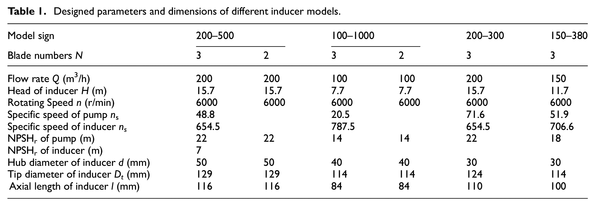
Four models of inducers were designed and used in a mine high-speed rescue pump (a multistage centrifugal pump): GFQ200-500, GFQ100-1000, GFQ200-300, and GFQ150-380. Table 1 shows the main designed parameters and dimensions of different inducer models. The entities are showed in Figure 1.
Designed parameters and dimensions of different inducer models.
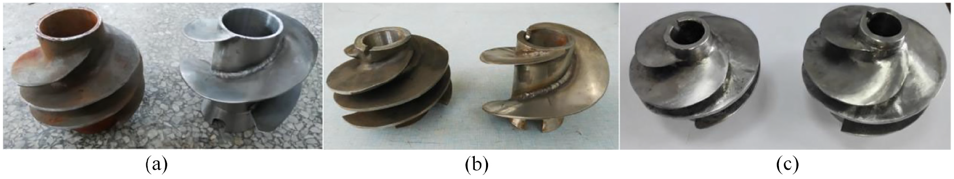
Different models of high-speed inducers with great flow rates: (a) GFQ200-500, (b) GFQ100-1000, and (c) GFQ200-300/GFQ150-380.
Experimental facilities
Hydraulic performance experimental facility
A dry-type speedy inverter motor has been used to rotate the inducer; the motor type is YVP-37-02. At the rated condition, output power is 37 kW, rated voltage is 380 V, rated frequency is 100 Hz, and rotating speed is 6000 r/min. Cornwall inverter of Bosch FSCG05 series is selected to control the motor rotating speed, with a rated power of 37 kW and frequency range of 0–400 Hz. Subsequently, the inverter data are integrated into the experimental control system, which included a start-stop device and digital software that collected the experimental data on flow rate, pressure, rotating speed, torque, etc.
Figure 2 shows the assembly diagram of the inducer experimental system. The flow in the inducer followed the axial direction (shown as the red arrow), which is the same as that in the axial pump. Mechanical seals (7) have been installed between the sliding bearing (6) and bearing box (8) to prevent liquid leakage from the inducer outlet. To cool the mechanical seals, a higher pressure liquid sourced from the outlet is used to wash the mechanical seal structure (represented by the “+” symbol in Figure 2).

Assembly diagram of the experimental platform of the high-speed inducer.
Figure 3 shows the closed experimental platform of the high-speed inducer. According to several principles, 33 the gross volume of the two tanks is 8 m3. A vacuum pump installed on top of the main tank is applied to decrease the inlet pressure of the inducer when studying the cavitation performance. During the hydraulic experiment, the inlet valve (3) is opened first and outlet valve (9) is turned down; subsequently, the motor and inducer are started. Liquid flows along the main tank, inlet pipe, inducer, elbow structure, deputy tank, and the connected pipe; finally, it returns to the main tank once again (shown as the green dotted arrow in Figure 3). Flow rate is controlled by adjusting the outlet valve (9). When the cavitation experiment is completed, the experimental flow rate is set after the entire unit achieves stability. Subsequently, the vacuum pump is opened and the inlet pressure is adjusted, the data on NPSH and H are obtained from the control system software. Repeated experiments are performed to avoid the interference of uncertain factors.
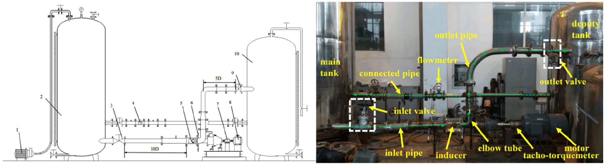
Closed experimental platform system for the high-speed inducer.
The TQ-660 torque sensor is used in this study with the maximum rotation speed of 30,000 r/min, torque exceeding 0 ± 100 N m, and torque error being ±0.2%. An electromagnetic flow meter is installed at the pipe connecting the main tank with the secondary tank; the flow rate ranges from 1.8 to 271 m3/h, and the flow rate error is ±0.2%. Pressure sensors are installed at the inducer inlet and outlet (left side of Figure 2). The inlet pressure sensor located in 4Dt (which Dt is tip diameter of inducer) upstream of the inducer blade leading edge, the outlet pressure sensor located in 2Dt downstream of the inducer blade trailing edge.25,26,33 The pressure measuring method utilizes measurement points located on the circumference of the experimental pipe to attain accurate data, and the error associated with the head is ±1.5%. A control system software is used to obtain data on the rotating speed, torque, flow rate, and pressure, which is followed by calculating and exporting the results of shaft power and head. Considering the residual uncertainty of the experimental instruments, methods, and uncontrolled test conditions in the measurement system, the uncertainty of pressure, flow rate, and torque measurements is ±0.571%, ±0.352%, ±0.329% respectively, the overall uncertainty is ±0.747%. 33
In this study, hydraulic and cavitation experiments of the designed inducer are conducted, and hydraulic curves at 3000 r/min (50 Hz), 4800 r/min (80 Hz), and 6000 r/min (100 Hz) are obtained to analyze the relationship between rotating speed and hydraulic performance. Cavitation experiments are mainly implemented under the specified flow rate, and the cavitation curves of independent inducers at 4800 r/min (80 Hz) and 4200 r/min (70 Hz) are plotted to investigate the relationship between ψ and σ.
Visualization experiment facility
It is well known that fluid machinery is covered by opaque materials. Therefore, it is difficult to easily determine the inner flow law and distribution of cavitation bubbles. Accordingly, a visualization experiment of the high-speed inducer has been performed, which elucidates the quantity and movement trail of bubbles generated by the inducer cavitation. The experimental system for the visualization test mainly contains a platform comprising the high-speed inducer, a high-speed camera, collection software, and a flashlight (Figure 4). For eliminating and compensating for the incident and reflection of the illumination light, the plexiglass tube has been designed to exhibit a round interior and a rectangular exterior (Figure 5).

Visual experimental system.

Visualized experimental plexiglass tube.
The high-speed camera used here is MotionPro Y4 of Midwestern Group, USA. Considering the experimental time, image quality, and size of shooting area, the shooting frequency of the high-speed camera equals the frequency associated with the inducer rotating one-twelfth of a circle; it takes about 0.83 ms to shoot one image and captures a total of 12 pictures after one rotation of the inducer. A 150 W centralized LED light source is selected as the flashlight.
In Figure 4, the high-speed camera and experimental transparency tube are perpendicular to each other at the same height. Meanwhile, the flashlight is located on the same side of the high-speed camera and aimed at the transparency tube of the inducer at a smaller oblique angle. The computer is near the main tank and used to collect the image of cavitation bubbles.
Visualization experiments are performed for the inducer by matching with the GFQ200-500 type high-speed rescue pump. The initial flow condition state is observed along with the generation and distribution of cavitation bubbles.
Results and discussions
Hydraulic and cavitation performance
Hydraulic and cavitation performances are analyzed in this section using the head coefficient
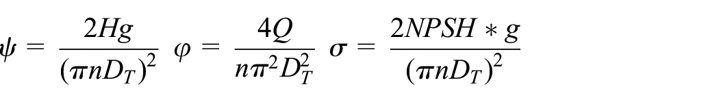
where
When calculating the shaft power of the inducer, it is necessary to subtract the power generated by the mechanical friction without load. Figure 6 shows the hydraulic curves for different high-speed inducer models at varying rotating speeds. By combining these results with Table 2, it is revealed that most of the experiments on the hydraulic performance of the inducer can be conducted at the designed flow rate and that all inducer heads exceed the designed values. Only the maximum flow rate of the GFQ200-500 inducer with three blades does not equal the designed value. Thus, the modern design theory for inducers does not produce accurate results. When the flow rate is 188 m3/h, the inducer head exceeds the designed value (17.52 m). The flow resistance of the inducer is enlarged by an increase in the experimental pipe dimensions and the elbow outlet structure, and the maximum flow rate is limited for the three-blade model. However, based on the mine high-speed rescue pump experiment, the GFQ200-500 pump with the three-blade inducer operates normally at the designed condition and the head meets with the designed value. Therefore, the GFQ200-500 inducer with three blades can work normally at the designed flow value when it is matched with the pump. A comprehensive literature study about the pressure sensor location and pressure measurement method had been conducted, The outlet pressure sensor located about 1.5 times diameter downstream of the blade trailing edges 25 , while it located about one diameter downstream of the blade trailing edges 26 . Although the right pressure sensor location and pressure measurement method had been selected, 33 the inducer outlet whirl disturbed the pressure distribution of outlet pipe and enlarged the uncertainly of measurements. In order to decrease the inducer outlet whirl disturb, it’s better to install a director at the inducer downstream, or extend the length of the inducer outlet pipe (in Figure 2 blue rectangular).
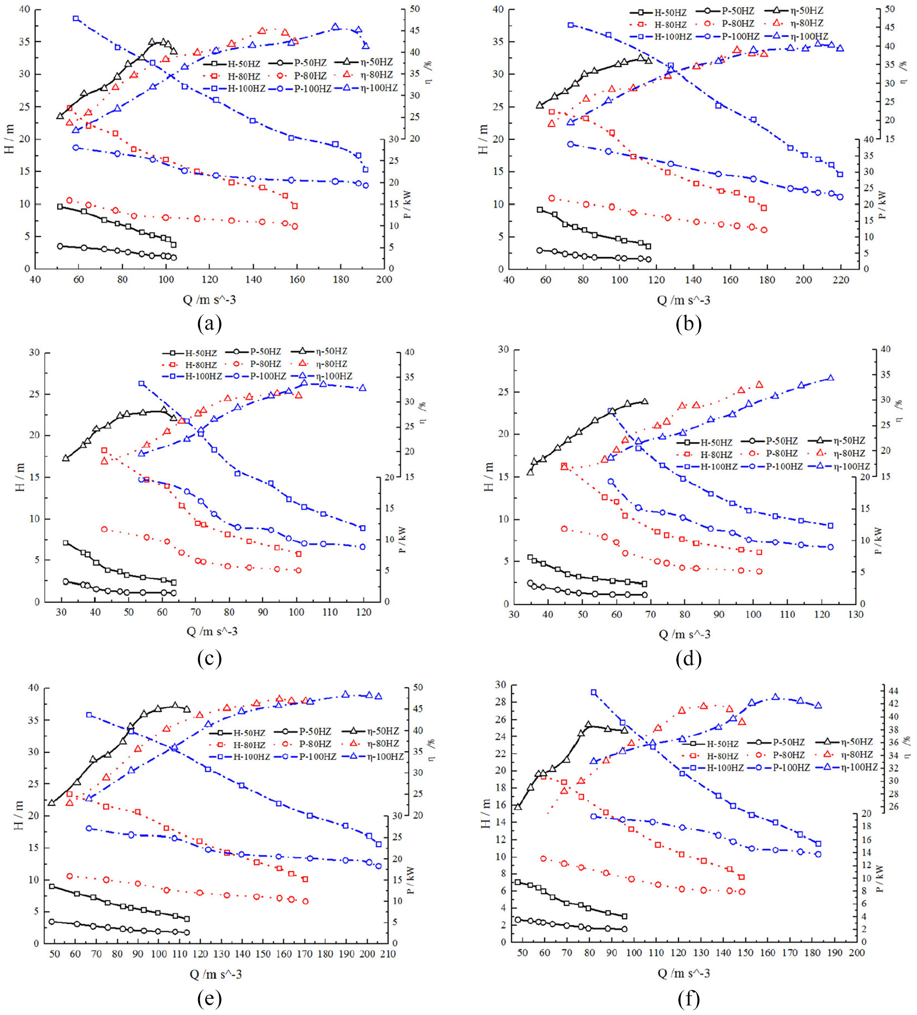
Hydraulic curves of different inducers: (a) GFQ200-500 type with three blades, (b) GFQ200-500 type with two blades, (c) GFQ100-1000 type with three blades, (d) GFQ100-1000 type with two blades, (e) GFQ200-300 type with three blades, and (f) GFQ150-380 type with three blades.
Head of the inducer at the designed flow rate condition (n = 6000 r/min).

Based on Figure 6(a) to (d) and Table 2, the head of the three-blade inducer is larger than that of the two-blade inducer at the same flow rate and rotating speed. When other dimensions are similar, an increased blade number can obtain more liquid volume and produce more hydraulic force. The differences in head variation at a greater flow rate between the GFQ200-500 and GFQ100-1000 type inducers may be because the designed flow rate of the latter is smaller than that of the former, while the experimental flow rate is less than the limit of the experimental pipe system.
Figure 6(e) shows that the relationship between H and Q for the GFQ200-300 type inducer is the same as the GFQ200-500 type; that is, the head drops sharply as the flow rate increases. When the flow rate exceeds 205 m3/h and comes close to the limit of the experimental pipe system, the head decreased sharply. Because the hub diameter of the GFQ200-300 type (30 mm) is smaller than that of the GFQ200-500 type, the flow area tends to increase along with the flow capacity.
Based on the P-Q curves, the shaft power decreases as the flow rate increases (gradient of decreasing is higher at a smaller flow rate) and the shaft power of two blades is slightly higher than that of three blades.
The η-Q curves reveal that the inducer efficiency enlarges with an increase in the flow rate; the efficiency is minimum occurs at smaller flow rates, while it is the maximum near the designed flow rate condition. Figure 6(d) and Table 3 show that the efficiency of the GFQ100-1000 type inducer with two blades has no inflection point appearing on the curve. Owing to the stronger flow capacity of the two-blade inducer, its maximum efficiency exceeds the test range. Meanwhile, the efficiency of the three-blade inducer is higher at the same flow rate and rotating speed.
Maximum efficiency of the inducer (n = 6000 r/min).

Figure 6(f) shows that the efficiency of the GFQ150-380 type inducer with three blades is lower at a smaller flow rate, because the impact loss is larger at smaller flow points; therefore, the proportion of disk friction loss in shaft power is larger.
The similarity law is often used to describe the relationship between the hydraulic parameters and the rotating speed. However, there are numerous deviations between the experimental results of different inducers at different rotating speeds, while the results of similarity transformation have several variations. Table 4 shows the results of the similarity transformation of the GFQ100-1000 type inducer; here, 3000/4800 stands for transforming the rotating speed from 3000 to 4800 r/min and so on. Flow rate, head, and shaft power deviation are the average values of relative deviation for the experimental data on the ratio of flow rate, head, and shaft power. At the corresponding rotating speed, the ratios of the flow rate, head, and shaft power are equal to the first, second, third power of the rotational speed ratio, respectively.
Results of the similarity transformation of GFQ100-1000 inducer.

The flow rate ratio of the inducer with the same blade numbers and different rotating speeds is close to the first power of the rotating speed ratio. The flow rate values, which similarly transform from lower to higher rotating speeds, are higher than their experimental values. The head ratio of the inducer is close to the second power of the rotating speed ratio. The inducer heads are similarly higher than their experimental values. The deviation between the shaft power ratio and the third power of the rotating speed is significant. At a higher rotating speed, the inducer efficiency is higher. Overall, the relationship between shaft power and rotating speed disagrees with the similar law theory.
Figure 7 shows the hydraulic curves of the high-speed inducer without cavitation at rotating speeds of 3000 r/min (50 Hz), 4800 r/min (80 Hz), and 6000 r/min (100 Hz). The ψ-φ curve has no relation with the rotating speed. That is, rotating speed has little influence on the dimensionless head-flow curve. Furthermore, changing the Reynolds number has negligible effect on the dimensionless head-flow curve. The relationship between the head coefficient and flow rate coefficient mainly followed a linear rule. In Figure 7(b), the ψ-φ curve of the GFQ100-1000 inducer with three blades is higher than that of the inducer with two blades; this result illustrates that the working capability of an inducer with three blades is larger than that of an inducer with two blades at the same flow rate, which is consistent with the above-mentioned experimental results.

Hydraulic curves without cavitation of the high-speed inducer: (a) GFQ200-500 (ns = 654.5), (b) GFQ100-1000 (ns = 787.5), and (c) GFQ200-300 (ns = 654.5)/GFQ150-380 (ns = 706.6).
Cavitation experiments were conducted at 4200 r/min (70 Hz) and 4800 r/min (80 Hz) for determining the strength of the plexiglass tube and the accuracy of results. The cavitation curves of the high-speed inducer at different rotating speeds are showed in Figure 8. The head value drops slightly at first when the cavitation number decreases; at this moment, only some cavitation bubbles appear in the flow passage of the inducer and disturb the mainstream flow. Most bubbles extrude to the inducer tip due to the higher-pressure liquid from the hub. As the cavitation number decreases, several cavitation bubbles are generated in the flow passage of the inducer, thereby blocking the flow passage, moving out of the mainstream, and significantly decreasing the head. This result is not the same as the cavitation curves of the centrifugal pump, where the head declines sharply when the inlet pressure decreases. A wide and short inducer blade structure is different from the narrow and long centrifugal pump blade structure, and the cavitation bubbles in the inducer generate and collapse for a long period of time; therefore, the head decreases sharply after the cavitation bubbles are generated and transmitted for a long period.

Cavitation curves of the high-speed inducer: (a) GFQ200-500, (b) GFQ100-1000, and (c) GFQ200-300/GFQ150-380.
The pump reaches a critical cavitation point when the inducer head becomes 1% (critical cavitation number). Table 5 shows the critical cavitation number for different inducer types. Based on the results of Figure 8, at 4200 r/min(70 Hz), the deviation of the critical cavitation number between the two-blade and three-blade inducers is extremely insignificant; therefore, the anti-cavitation performance of the two inducers is almost the same. At 4800 r/min(80 Hz), decreasing of the designed flow rate and head may slightly improve the anti-cavitation performance of the two-blade inducer than that of the three-blade inducer. In general, anti-cavitation performance of the inducer with three blades is superior. The anti-cavitation performance of the GFQ200-300 type inducer is superior than the GFQ150-380 type inducer at 4800 r/min(80 Hz).
Critical cavitation number of different inducer types.

The cavitation number ratio at different rotating speeds is not equal to the second power of the rotating speed ratio; therefore, it does not obey the cavitation similarity law. The cavitation number values, which similarly transform from lower to higher rotating speeds, are higher than their experimental values for the same inducer type.
Distribution of the cavitation bubbles
Figure 9 shows the inner flow conditions of the inducers with three and two blades at the rotating speed of 4800 r/min(80 Hz), 5400 r/min(90 Hz), and 6000 r/min(100 Hz) when the vacuum pump closed. At this moment, the inlet pressure equals to the atmosphere pressure. At 4800 r/min (80 Hz), several bubbles appear at the blade inlet (leading edge of the inducer with two blades), thereby indicating that the vortex cavitation generates in the inducer with two blades. At 5400 r/min (90 Hz), many bubbles with different dimensions generate in the flow passage of the inducer with different blade numbers. The vortex cavitation emerges at the blade inlet (leading edge of inducer with three-blades). The vortex cavitation of the inducer with two blades expands to the downstream along with the axial direction of the blade, and develops into wedge-shape sheet cavitation at the leading edge. Compared to that at 4800 r/min (80 Hz), area of the cavitation domain increases significantly at 5400 r/min (90 Hz). It is suggested that several cavitation bubbles appear at the leading edge of the blade inlet at the designed condition, generate vortex cavitation, and gradually expand into the wedge-shape sheet cavitation domain along the rotation surface of the blade. For the theoretical design, the Brumfield principle defines that no cavitation phenomenon appears at the fluid machinery inlet. However, the inlet pressure of the high-speed inducer exhibits a low vaporization pressure of the working liquid when the rotating speed is 6000 r/min(100 Hz). This indicates that although a slight cavitation phenomenon has already appeared, the hydraulic performance of the inducer has not been influenced; therefore, the anti-cavitation performance of the designed inducer can be achieved. By comparing the inner flow distribution of inducers with different blade numbers, it is revealed that the anti-cavitation performance of the three-blade inducer is superior to that of the two-blade inducer.

Distribution of cavitation bubbles in inducers with different rotating speeds at the initial pressure.
The cavitation stage of the inducer can be controlled by reducing the pressure of the main tank by starting and stopping the vacuum pump, and the distribution and scale of the cavitation bubbles during the cavitation stage can be recorded using the high-speed camera. The law governing the cavitation flow of the inducer is analyzed and obtained. According to the volume distribution of the cavitation bubbles, inducer cavitation can be divided into inception, developing, and developed stages.
Figure 10 shows the distribution of the cavitation bubbles that rotate one circle at the cavitation inception stage at 4800 r/min (

Distribution of cavitation bubbles at the cavitation inception stage.
The inlet pressure of the inducer declines slightly due to vacuum pumping. The number of cavitation bubbles in the inducer decreases gradually when the inlet pressure decreases, thereby entering the cavitation developing stage wherein the cavitation number of the inducer is 0.141 (NPSH = 5.7 m) (corresponding to the position of point “b” in Figure 8(a)). Figure 11 shows the distribution of the cavitation bubbles at the cavitation developing stage. The amount and area of cavitation bubbles are larger for the two-blade inducer. Owing to the tip clearance and pressure difference between the two blade sides, tip leakage vortex occurs. Consequently, tip leakage vortex cavitation gradually expands to the downstream along the rotation direction of the inducer, thereby deforming the wedge-shape sheet cavitation domain; finally, bubbles collapse at the downstream higher-pressure zone finally. The area and duration time of the wedge-shape sheet cavitation zone of the two-blade inducer are larger than those of the three-blade inducer. Furthermore, the movement of cavitation bubbles in the two-blade inducer is more dramatic. Figure 8(a) shows that at the “b” location, the head of the inducer with three and two blades declines and becomes 0.03 and 0.08 m less than the stipulated condition. Therefore, the inducer head only drops slightly at the cavitation developing stage, which indicates that the inducer can operate extremely well.

Distribution of cavitation bubbles at the cavitation developing stage.
With a decrease in the inlet pressure of the inducer, the cavitation bubbles enter the developed stage. The cavitation number of the inducer is 0.112 (NPSH = 4.5 m), corresponding to the location of “c” in Figure 8(a). At the cavitation developed stage (Figure 12), several cavitation bubbles are generated and cover the entire flow passage of the suction surface at the leading edge of the inducer inlet. The diameter of cavitation bubbles also increases and expands into the next blade inlet, based on the mainstream flow dynamics. The flow angle of the adjacent blades is influenced by the increase in the area of the cavitation zone, which further aggravates the cavitation generation and thus partial cavitation bubbles start to block the flow passage.

Distribution of cavitation bubbles at the cavitation developed stage.
Owing to an increase in the pressure difference between the two sides of the blade, partial flow at the inducer blade tip clearance is pushed toward the inlet direction, thereby assuming a direction opposite to the mainstream flow direction and forming a back flow vortex. Back-flow vortex cavitation appears at the lower-pressure vortex core; it combines with the tip vortex cavitation, forms wedge-shape sheets and cloud cavitation, and blocks the entire flow passage. This phenomenon is particularly observed in the two-blade inducer. The collapse and regeneration of cavitation bubbles of the two-blade inducer occur continuously, and the vibration and noise of the experimental platform become more severe. The head of the inducer with three and two blades is reduced by 1.1%–1.9%, respectively; however, the inducer head never by reduced by 3% for both the inducers (Figure 8(a)). This result may be due to the action of the pushing force caused by the centrifugal dynamic at the inducer tip location and the higher-pressure liquid dynamic at the downstream. Although development of the cavitation bubbles has little effect on the mainstream and downstream flows of the inducer, the process itself is very violent.
Conclusions
Based on the results of the hydraulic performance experiment for different high-speed inducers, the changing tendency of the hydraulic parameters (such as the head, shaft power, and efficiency) with the flow rate is in accordance with the hydraulic performance curves of the axial pump. With an increase in the flow rate, the gradient associated with head reductions becomes larger, shaft power declines slightly, and the efficiency first increases and then decreases; the maximum efficiency appears at the inflection point. Furthermore, the experimental results indicate that all inducers meet the design requirements; however, all inducer heads exceed the designed values, thereby revealing the inaccuracy of the modern design theory.
By combining the relationship between the hydraulic performance and the rotating speed, the similarity law theory is appropriated to the relationship between head, flow rate, and rotating speed. However, the theoretical calculations associated with the similarity law from lower to higher rotating speeds are greater than the experimental values. The law between shaft power and rotating speed disagrees with the similarity law theory; moreover, the inducer efficiency increases at a higher rotating speed.
Based on the cavitation performance curves, the inducer head first declines slightly when cavitation number decreases; however, it declines greatly during the developed stage. At 4200 r/min (70 Hz), anti-cavitation ability of the inducer has no connection with the blade numbers. The relationship between cavitation number and rotating speed disagrees with the cavitation similarity law theory, and the NPSH translating from lower to higher is greater than the experimentally measured value at a higher speed.
Based on the results of the visualization experiment, the designed inducer can perform the function of anti-cavitation under normal conditions, and the anti-cavitation ability of the three-blade inducer is superior than that of its two-blade counterpart. Cavitation bubbles first appear on the suction surface of the blade inlet leading edge, and vortex cavitation appears at the cavitation inception stage (
Footnotes
Appendix I
Handling Editor: Chenhui Liang
Declaration of conflicting interests
The author(s) declared no potential conflicts of interest with respect to the research, authorship, and/or publication of this article.
Funding
The author(s) disclosed receipt of the following financial support for the research, authorship, and/or publication of this article: This work was partly supported by the Natural Science Foundation of the Jiangsu Higher Education Institute of China (No. 19KJD470006), Natural Science Foundation of Jiangsu Province (Grant No. BK 20190847), China Postdoctoral Science Foundation (2019M661744), and China Postdoctoral Science Foundation (2021TQ0130).
Data availability
The data that support the findings of this study are available from the corresponding author upon reasonable request. The authors have no conflicts to disclose.