
Abstract
The elastic deformation of the front subframe during vehicle traveling affects the vehicle handling stability. The static equilibrium equations of the suspension and subframe system and the kinematics equations of the three-degree-of-freedom vehicle are established to illustrate the principle of the influence of the flexible front subframe on the handling stability. The front subframe is flexibly processed to establish a rigid-flexible coupled vehicle model. Simulations of the suspension kinematic and compliance alongside sine swept steering simulation of the vehicle are performed. The front subframe bushing stiffness, which has a greater impact on the handling stability, is selected as a design variable through parametric test design, and the NSGA-II algorithm is used for multi-objective optimization with the vehicle handling stability evaluation index as the optimization target. The simulation results show that the flexible front subframe will make the bushing force change to affect the suspension kinematic and compliance characteristics and then affect the vehicle handling stability, the gain of vehicle yaw rate and the delay time of lateral acceleration decrease, while the gain of roll angle increases. The optimization results show that the optimized vehicle exhibits improvements in the yaw rate gain, delay time of lateral acceleration, and roll angle gain.
Keywords
Introduction
The handling stability of a vehicle is an important part of the vehicle’s performance, affecting the driver’s road feel and comfort level when driving. Vehicle handling stability has strict design standards. Under the condition of meeting the basic performance requirements, the handling stability of vehicles is the main consideration for people to buy vehicles. Therefore, the research and optimization of handling stability has become a hot research topic in recent years.1,2
Scholars have conducted extensive research on the handling stability of vehicles, primarily focusing on optimizing suspension parameters or developing novel suspension systems to enhance vehicle handling stability. Gokul and Malar 3 innovatively designed an adaptive air suspension system with an LQR control strategy, ensuring vehicle stability while improving ride comfort. Chen et al. 4 proposed a mechanically interconnected balance suspension, linking the front and rear suspension movements through a lever mechanical connection structure to enhance overall performance in ride comfort and handling stability. Zhang et al. 5 optimized vehicle handling stability by considering suspension roll center height, equivalent steering stiffness, and roll steering coefficient as optimization objectives, improving the vehicle’s handling stability through optimization of suspension hardpoint coordinates and bushing stiffness. Qi et al. 6 developed a novel suspension system that resolves the conflict between vehicle handling stability and ride comfort. Li et al. 7 optimized automotive handling stability based on D-optimal experimental design. Jeong et al. 8 conducted structural optimization research on automobile rear torsion beam suspension, enhancing overall vehicle handling stability characteristics. However, the above studies mainly focus on the influence of vehicle suspension on vehicle handling stability and optimization design. The front subframe, as another important component affecting vehicle handling stability, has been studied less on how it affects handling stability. Therefore, it is necessary to study the effect of front subframe on vehicle handling stability. Based on Adams/Car model, Tey et al. 9 converted the performance objectives of ride comfort and vehicle handling stability into a multi-objective optimization problem for optimal design, and took suspension size as the design constraint. Zhang et al. 10 established a vehicle virtual prototype model and carried out an optimization study on handling stability based on the model using NSGA-II algorithm.
In recent years, parameterized modeling and simulation analysis based on rigid-flexible coupled models have been widely utilized in the field of vehicle simulation. 11 Deng et al. 12 established a rigid-flexible coupled model with flexible tires to improve research efficiency and accuracy. Jothi et al. 13 developed a rigid-flexible coupled vehicle model with flexible track wheel arms, modeling the wheel arms as flexible elements to capture the vehicle’s dynamic characteristics.
In order to balance the handling and driving characteristics of a vehicle, Wu et al. 14 established a rigid-flexible coupled model for a mining dump truck. Jiang et al. 15 designed a rigid-flexible coupled vehicle model that integrates flexible control arms and torsion beams, focusing on lightweight design research for suspension components.
Therefore, it is necessary to treat the components of the vehicle that undergo elastic deformation during operation with flexibility. As part of the suspension system, the front subframe’s elastic deformation has a significant impact on vehicle handling stability. Thus, it is essential to consider the flexibility of the front subframe when studying vehicle handling stability to obtain an accurate vehicle dynamics model. Previous studies have also examined vehicle subframes. Wang et al. 16 combined improved NSGA-II with TOPSIS for hybrid lightweight design of a specific front subframe. Feng et al. 17 demonstrated the feasibility of manufacturing subframes using magnesium alloy by altering the material properties and improving the structure. Front subframes typically have complex and diverse structures, connecting the axle and suspension to the main frame, significantly affecting vehicle handling stability. However, the aforementioned studies mainly focused on the structure and lightweight design of front subframes, without investigating the impact of flexible front subframes on vehicle handling stability. Furthermore, past simulations of overall vehicle handling stability typically treated the front subframe as rigid, resulting in significant discrepancies between simulation results and road test results. Utilizing finite element methods for vehicle handling stability simulation analysis with a flexible front subframe allows for the consideration of the front subframe’s elasticity, 18 resulting in more accurate simulation results.
This paper mainly investigates the following key points: (a) Derivation of static equilibrium equations for the suspension and subframe system, as well as three-degree-of-freedom vehicle kinematics equations, elucidating the principle of how flexible front subframes influence handling stability. (b) Utilizing HYPERMESH software to subject the front subframe of vehicle to flexible treatment, generating its MNF (Modal Neutral File) file, and validating through modal analysis that the front subframe will not resonate with the vehicle body or engine. (c) Establishment of a vehicle rigid-flexible coupled model with a flexible front subframe, conducting suspension KC (Kinematic and Compliance) characteristics and sine sweep steering simulation analyses. (d) Through sensitivity analysis, the bushing stiffness at the junction of the front subframe with the vehicle body and suspension, identified as having a significant impact on handling stability, was selected as a design variable. The NSGA-II algorithm was employed to conduct multi-objective optimization of overall vehicle handling stability characteristics.
Modeling method of hinge point load calculation for suspension and subframe system
Suspension and front subframe modeling
Before establishing the static equilibrium equations for a suspension system with a front subframe it is first necessary to model the bushings and ball hinges in the suspension and subframe system and to calculate the displacements and forces of the bushings, among others. The front suspension of the vehicle referenced in this paper is a double wishbone independent suspension, and the front subframe is elastically connected to it through bushings. Therefore, the front subframe and double wishbone independent suspension are modeled and the forces at each ball hinge and bushing in the front suspension and subframe system are analyzed. Because the control arms in the left and right double wishbone independent suspension are symmetrically distributed, the right control arm along the forward direction of the car is chosen as an example for the study, and its structure is shown in Figure 1.

Single-sided double wishbone independent suspension structure.
From Figure 1, it can be observed that bushings E and F connect the upper control arm to the vehicle body, while the lower control arm is connected to the front subframe via bushings C and D. The wheel steering knuckle is connected to the upper and lower control arms through ball joints K and H, respectively. The tie rod is connected to the steering system and steering knuckle via ball joints M and N. Additionally, the spring and shock absorber are connected to the lower control arm and the vehicle body through ball joints P and T, respectively. The
The suspension and front subframe system are modeled based on the following assumptions:
- Considering the tie rod, wheel steering knuckles, and control arms to be rigid structures while ignoring tire deformation;
- Neglecting the frictional forces at each joint in the model of the suspension and the front subframe;
- The motion of the suspension and subframe system is quasi-static at all extreme operating conditions of the vehicle, so that the inertial and damping forces are zero at each condition;
- The gravity of each component of the model and the powertrain on the load of the joint point of the system is also ignored;
- The steering movement is not considered, and the tie rod is assumed to be fixed at the connection end of the steering gear.
Calculation of point’s new position in the rigid body
According to the definition of rigid body, the relative position of each internal point remains unchanged after motion and stress, that is, the position vectors of any two points remain unchanged in the LCS. If the coordinate transformation matrix

Assume coordinates


Where
If the matrix

At this point,
Bushing modeling
In automobile suspension systems, apart from ball joints, most connections utilize bushings. The front subframe is connected to the vehicle body via bushings to reduce vibration and noise from the ground. Figure 2 shows the translational stiffness and rotational stiffness of the bushing model, where the translational stiffness is denoted by

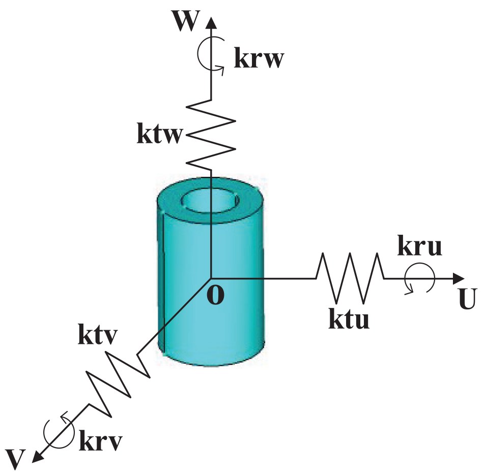
Bushing model.

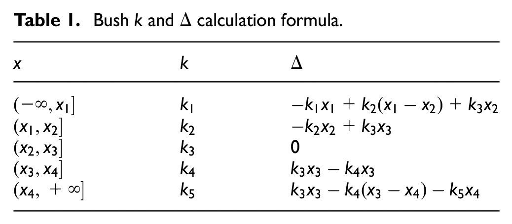
Piecewise linear force-displacement diagram of the bushing in one direction of its LCS.
The relative displacement in the LCS is denoted by
Bush
Calculation of the new position of the hinge point
The new coordinates

Where,
The new coordinates

Where,
The new coordinates

Where,
Using equation (4), the new coordinates are calculated by taking point BL on the subframe in Figure 4 as the reference point. The new positions

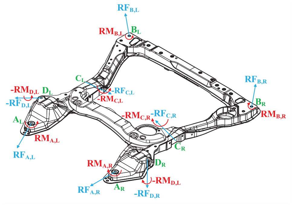
Schematic diagram of force on front subframe.
Where the initial positions of the ball hinge for
The displacement of the bushings and springs can be more accurately measured if an external load is supplied to the suspension, as shown by equations (6)–(9), which allow for the determination of all new positions for each ball hinge and bushing.
Calculation of bushing force and displacement
The displacement calculation equation of the bushing

Where the
The forces and torques exerted on the bushing in GCS due to bushing displacement are:

Where,


are the translational stiffness matrix and rotational stiffness matrix of bushing s in GCS, respectively;
According to equation (11), assuming that the displacement of the ball hinge

Where,

Then the antisymmetric matrix

Where,
According to equation (11), assuming that the displacement of the joint

Where,
Figure 4 shows the front subframe subjected to the combined forces and moments of bushings

Where,
Establishment of balance equation of suspension and subframe system
As the left and right control arms are symmetrically distributed in the suspension and subframe system, the research is carried out with a single side control arm. The lower control arm achieves equilibrium through the interplay of bushing, spring and ball hinge, with the equation expressed as:

Where,

Where,
Similarly, the upper control arm static equilibrium equation is:
Where
All the control arms in the suspension and subframe system are analyzed separately for forces according to the above steps. The left and right side forces, moments and position vectors are distinguished by the subscripts L, R. The equations for the control arms in the suspension and subframe system are:

As the left and right steering knuckles are symmetrically distributed in the suspension and subframe system, the research is carried out with a single side steering knuckle. The wheel steering knuckle achieves equilibrium through the interplay of the control arm, tie rod, and external load, with the equation expressed as:
Where,

Where,
According to the above steps, the force analysis of the steering knuckle in the suspension and subframe system is carried out respectively. The equilibrium equation of the steering knuckle in the suspension and subframe system is:

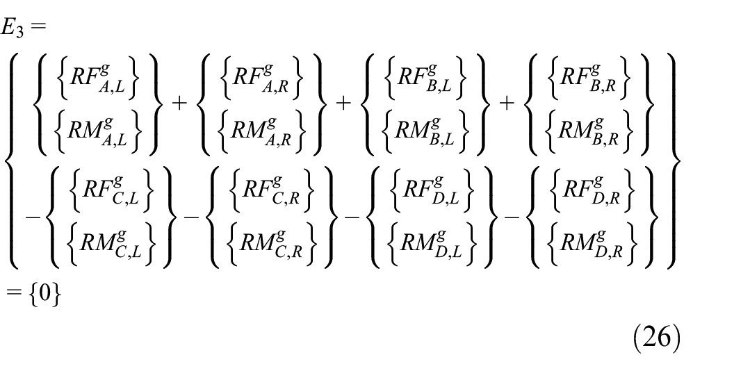
The front subframe is in equilibrium under the combined effect of the bushing forces and moments at the left and right
The equation between the initial length of the spring and the new length after the elastic deformation and the resulting displacement is expressed as:

Where

Where
The steering tie rod is a rigid bar whose length remains constant and the constraint equation is:

Where
According to the above steps, the force analysis of the left and right springs and steering knuckles is carried out respectively. The left and right-side forces, torques and position vectors are distinguished by lower Angle symbols L and R respectively, and the constraint equations established are:

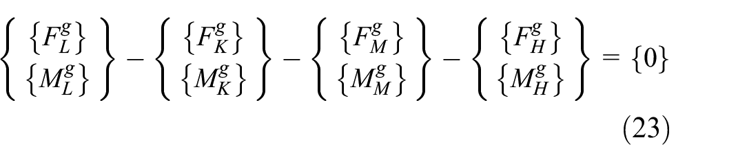
Combining the equilibrium equation, (22), (25), (26) and the constraint equation (30), the equilibrium equations for the suspension and subframe system are expressed as:

From equations (22), (26), and (31), it can be seen that the bushings A, B, C, and D at the articulation of the front subframe with the body and the suspension will affect the force on the suspension system, while the elastic deformation of the flexible front subframe will change the displacements of the four bushings, which will in turn cause changes in the reaction forces and suspension displacements applied to the suspension. Therefore, the elastic deformation of the flexible front subframe further affects the KC characteristics of the suspension system through the bushings A, B, C, and D, thereby affecting the vehicle handling stability.
Dynamics analysis of vehicle considering roll
In the preceding section, this paper analyzed the forces acting on the bushings of the front suspension and subframe system, investigating the relationship between the flexible front subframe and the suspension. To further explore the vehicle’s handling stability, this section will conduct kinematic analysis considering vehicle roll. Vehicle is a complex nonlinear system, the body and wheels are elastically connected through the suspension and subframe system, and the body is said to be the unsprung mass and the wheels are the unsprung mass, in this case the vehicle will be subject to centrifugal force and thus lateral inclination motion when it is performing lateral motion.
Therefore, in order to describe the driving state and characteristics of the vehicle more accurately, a nonlinear three-degree-of-freedom vehicle equivalent kinematic model describing the lateral, yaw and roll motions at the same time is established as shown in Figure 5. The meanings of the relevant symbols are listed in the Appendix.

Three-degree-of-freedom equivalent dynamics model: (a) external forces acting on tires and (b) rolling moment acting on the car body.
When a vehicle undergoes rolling motion, it is subject to a complex interplay of forces, including the inertial force arising from the unsprung mass and sprung mass, as well as the lateral force applied to the tire. This results in the emergence of a lateral force, a transverse moment, and a roll moment, all of which are intricately balanced with one another. As a result, the dynamic equation for the three-degree-of-freedom vehicle with body roll can be expressed as follows:

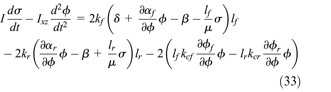

The Laplace transform is applied to equations (32)–(34) and the characteristic equations are expressed as:

Based on equations (32)–(35), the transfer function of vehicle with respect to


In equations (35)–(37),


From equations (38)–(39), it is evident that the vehicle’s yaw rate
Finite element modeling and analysis of front subframe
In the second and third sections, this paper analyzed the forces acting on the front suspension and subframe system, and theoretically examined the influence of the flexible front subframe on the vehicle’s handling stability response. This section will utilize finite element methods to subject the front subframe to flexible treatment, and establish a vehicle rigid-flexible coupled model incorporating the flexible front subframe. This prepares for further simulation analysis of the impact of the flexible front subframe on the vehicle’s handling stability.
Establishment of front subframe flexible body model
The front subframe used in this study is the CATIA 3-dimensional geometric model of a vehicle’s front subframe, which is imported into HYPERMESH software to establish a finite element model of the front subframe. Because the model comes with many connecting parts, the structure is more complex, the meshing is difficult and the quality of the mesh is difficult to ensure. The RBE2 rigid unit can transfer the force to each component to make the front subframe model become a whole, which can effectively replace the role of the connecting parts. Therefore, some of the bolts and other connecting parts are omitted and the RBE2 rigid unit is used to connect the front subframe components to clean up its geometry, based on which a triangular shell unit with a size of 4 mm is used for meshing, and the generated finite element model of the front subframe is shown in Figure 6.

Finite element model of front subframe.
The generated finite element model of the front subframe has 454,732 nodes and 1,339,927 units. In the Figure 6,

External connection node at the articulation point
The modal calculation of the front subframe finite element model is carried out using the CB modal method, considering the time used for the analysis and the size of the final generated file, the first 16 orders are taken for the operation to generate the Modal Neutral File (MNF) of the front subframe. The MNF file contains geometric information of the front subframe flexible body, node positions and their connections, node mass and inertia, modal, modal mass and modal stiffness, and other information. By utilizing MNF files in ADAMS to consider the influence of flexible body components, simulation accuracy can be improved and the motion of the entire system can be simulated more accurately. The material properties selected for the front subframe are shown in Table 2.
Material properties of the front subframe.

Modal analysis
A method for investigating the structure’s dynamic characteristics is modal analysis. It is capable of calculating the dynamic properties of a linear structure, such as its effective mass, natural frequency, mode shape, and mode participation coefficient. The main role of the front subframe is to reduce the adverse effects of road roughness and engine vibration, and its natural frequency and excitation frequency range may overlap to produce resonance, damaging the vehicle handling and driving performance. Therefore, it is necessary to conduct modal analysis on the front subframe to investigate its natural frequency and mode. Since the effective mass of low-frequency mode is larger, it is easier to be excited, and the effect is more accurate. Therefore, on the basis of the previous force analysis and under the condition of constraint on the hinge points of
Figure 8 shows the schematic diagram of the modal vibration pattern of the first four orders of the finite element model of the front subframe, and the corresponding intrinsic frequency and vibration pattern are shown in Table 3.

Front subframe front fourth-order modal analysis: (a) first-order mode shape, (b) second order mode shape, (c) third-order mode shape, and (d) fourth-order mode shape.
Modal analysis results of front subframe.

The vehicle dynamics model used in this paper has an engine idle speed of 800 r/min, a rated speed of 2700 r/min, and a corresponding engine excitation frequency of 26.7–90 Hz. The suspension and body excitation caused by road conditions typically fall within a frequency range not exceeding 25 Hz. As shown in Table 3, the range of intrinsic frequency of the front subframe avoids the range of intrinsic frequency of the body and the engine, and does not resonate, which meets the vibration performance requirements.
Establishment of vehicle rigid-flexible coupled model
The vehicle model includes subsystems such as double wishbone independent front suspension with front subframe, multilink independent rear suspension with rear subframe, tires, body, powertrain, steering system, etc.
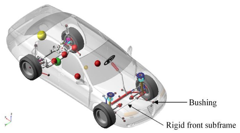
According to the topological relationship, the above subsystems are assembled to obtain the multi-body dynamic model with a rigid front subframe of the whole vehicle, as shown in Figure 9. The flexible body model of the front subframe was imported into the front suspension subsystem and connected with other components through external nodes, replacing the original rigid front subframe to establish the vehicle rigid-flexible coupled model, as shown in Figure 10. The tire model used is the PAC2002 tire model with good stability, and the main parameters of the tire model and the whole vehicle are shown in Table 4.
Rigid model.

Rigid-flexible coupling vehicle model.
Main parameters of tire and vehicle.

Comparison of simulation results between rigid model and rigid-flexible coupled model
Reverse wheel jump simulation
In this paper, the multi-body dynamic model with a rigid front subframe is named as the rigid model as shown in Figure 9, and the multi-body dynamic model with a flexible front subframe is named as the rigid-flexible coupled model, as shown in Figure 10, where the rigid front subframe and flexible front subframe is hinged with the suspension and the body by bushing.
In order to study the influence of the flexible front subframe on the KC (Kinematic and Compliance) characteristics of the suspension and subframe system, ADAMS software is used to perform the reverse wheel hop simulation and force simulation under the same conditions for the rigid model and the rigid-flexible coupled model. The evaluated indexes include: toe angle, camber angle and roll stiffness.
In the simulation test, the right and left wheels beat in the opposite direction, and the up and down beating volume of the wheel center is 80 mm, in order to simulate the rolling condition of the body relative to the road when the vehicle turns. In the force simulation of the suspension and subframe system, a maximum lateral force of 3000N and a minimum lateral force of −3000N are applied to the left and right wheels respectively.
Figures 11–13 shows the curves of the toe angle, camber angle and suspension system roll stiffness with wheel jump for the rigid model and the rigid-flexible coupled model in the reverse wheel jump condition. From Figures 11 to 13, it can be seen that the flexible front subframe affects the suspension K-characteristics, and the toe angle, camber angle and suspension system roll stiffness change when the vehicle jumps up and down after the front subframe is changed from rigid to flexible, which is in line with the conclusion in Section 2 that the front subframe affects the displacement of the suspension system and thus affects the suspension K-characteristics.

Toe angle variation curve with wheel jump.

Camber angle variation curve with wheel jump.

The roll stiffness of suspension system varies with wheel jump.
Figures 14–16 show the curves of the toe angle, camber angle and suspension system roll stiffness with lateral force for the rigid model and rigid-flexible coupled model force simulation conditions.

Toe angle variation curve with lateral force.

Camber angle variation curve with lateral force.

The roll stiffness of suspension system varies with lateral force.
From Figures 14 to 16, it can be seen that the flexible front subframe also affects the suspension C characteristics, and the toe angle, camber angle and suspension system roll stiffness of the rigid-flexible coupled model show a tendency to decrease relative to that of the rigid model when the same amount of lateral force is applied to the wheels. Combined with the theoretical analysis in Section 2, it can be seen that the elastic deformation of the flexible front subframe will change the force on the bushing at the articulation with the suspension lower arm and the body, which will change the force on the suspension system, and then affect the C characteristics of the suspension.
Sine-swept steering input simulation
In this paper, in order to study the frequency response characteristics of vehicles, sine swept steering input simulation of rigid model and rigid-flexible coupled model are compared and analyzed to study the effect of flexible front subframe on the simulation of vehicle handling stability. The evaluation indexes of vehicle handling stability are: the gain of steering wheel angle from yaw rate f1, the gain of lateral acceleration from roll angle f2, and the delay time of steering wheel angle from lateral acceleration f3, respectively.
For the frequency characteristics, only the range from

Sine swept steering simulation results: (a) f1, (b) f2, and (c) f3.
Figure 17(a) shows the comparison curves of different models f1 in the sinusoidal swept steering simulation in the frequency range of 0–1.5 Hz. From the Figure 17(a), the flexible front subframe will make the evaluation index f1 decrease and the vehicle handling stability is improved. Combining the theoretical and simulation analyses in Sections 3 and 5.1, it can be seen that the elastic deformation of the flexible front subframe will make the suspension KC characteristics change, and the changes in the toe angle and the suspension system roll stiffness will affect the
Figure 17(b) shows the comparison curves of different models f2 in sine swept steering simulation in the frequency range of 0–1.5 Hz. From Figure 17(b), the flexible front subframe will make the evaluation index f2 increase and the vehicle handling stability decrease. This is mainly because the flexible front subframe will cause a change in the roll stiffness, and the simulation results of the evaluation metric f2 are changed as a result, which is also verified in Section 5.1, indicating that the reduction of roll stiffness in the suspension system will lead to an increase in the roll angle gain f2.
Figure 17(c) shows the comparison curves of different models f3 in the sinusoidal swept steering simulation in the frequency range of 0–1.5 Hz. From Figure 17(c), the flexible front subframe will make the absolute value of the evaluation metric f3 lower, the vehicle can better respond to the driver’s commands, and the vehicle handling stability is improved.
Optimization of vehicle handling stability
Sensitivity analysis of the influence of front subframe bushing stiffness on handling stability
As shown in Figure 6, the front subframe is connected to the body through bushings A and B, and at the same time connected to the lower arm of the double-wishbone suspension through bushings C and D. There are eight bushings on the left and right, denoted by L and R. Each bushing has translational stiffness and rotational stiffness in three directions of x, y, and z respectively. Taking bushing A as an example, the three translational stiffnesses are denoted as
The flexible front subframe will change the handling stability of the vehicle. However, as it is subject to the forces and moments of a total of eight left and right bushings, there are 48 stiffness values which do not all have the same degree of influence on maneuvering stability, so a sensitivity analysis of the bushing stiffness is required before the optimization analysis can be performed.
In this paper, the DOE method of parametric testing is used for sensitivity analysis.
20
The right and left bushings of the front subframe are in a symmetrical relationship, therefore a total of 24 stiffness values of the four right side bushings

(a) Effect of bushing stiffness on f1, (b) effect of bushing stiffness on f2, and (c) effect of bushing stiffness on f3.
Figure 18(a) demonstrates the results of the sensitivity analysis of the stiffness of the right bushing of the front subframe to f1. The translational stiffnesses of the bushings A, B, C in the y-direction and their quadratic terms have a greater effect on f1.
Figure 18(b) demonstrates the results of the sensitivity analysis of the bushing stiffness on the right side of the front subframe to f2. The torsional stiffness of the bushing C, D in its z-direction has a large effect on f2.
Figure 18(c) shows the results of the sensitivity analysis of the bushing stiffness on the right side of the front subframe to f3. The translational stiffnesses of bushing A, B, C, D in the y-direction and their quadratic terms have a large effect on f3.
Considering the above sensitivity analysis results comprehensively, the translational stiffness of bushings A, B, and C in the y direction and the torsional stiffness of bushings C, D in the z direction is selected as design variables to optimize the handling stability.
Optimization mathematical model
The lateral stiffness of the bushing contributes significantly to the suspension stiffness, which affects the f1 and f3. The torsional stiffness of the bushing contributes significantly to the roll stiffness, which is used to investigate the f2. In order to achieve the purpose of improving the vehicle handling stability characteristics, the bushing stiffness at the articulation of the front subframe with the body and the lower control arm of the suspension, which has a greater influence on the vehicle handling stability characteristics, has been selected as an optimization variable through sensitivity analysis in the previous subsection.
The evaluation indicators f1 and f3 reflect the transient understeer of the vehicle and the speed of vehicle response, respectively. In general, a smaller f1 favors vehicle stability and a smaller f3 favors vehicle maneuverability. Therefore, f1 and f3 should be optimized in the smaller direction. While f2 reflects the vehicle transient anti-roll performance and should be optimized in the smaller direction. Therefore, in this paper, the handling stability evaluation indexes f1, f2, and f3 when the driver’s operating frequency is 0.5 Hz are selected as the optimization objectives, and the multi-objective optimization problem of the bushing stiffness at the connection between the front subframe and the body and the lower control arm of the suspension can be expressed as:

Optimization algorithm
The NSGA-II algorithm proposed by K. Deb is one of the multi-objective evolutionary algorithms.21,22 Compared with the traditional genetic algorithm, NSGA-II has greatly improved the iteration convergence speed, ensured the diversity of the population and reduced the complexity of iteration. Figure 19 shows the procedure of NSGA-II algorithm, the steps are as follows.
Step 1. Randomly generate an initial population Pt of size N (t = 0) according to the problem range and constraints, where t represents evolutionary algebra. Generate a population of offspring Qt (t = 0) from Pt using binary tournament selection, recombination, and mutation operators.
Step 2. Merge populations Pt and Qt to form a new population Rt of size 2N. Sort the population Rt according to non-domination, and divide it into several frontiers (F1, F2, F3, …), and then calculate the crowding distance of a group of individuals.
Step 3. The new population Pt+1 selects the optimal solution in F1. If the size of F1 is smaller than Rt, all members of the set F1 are selected, and the remaining members are selected in the order of crowding distance and nondominated fronts ranking.
Step 4. Selection, crossover, and mutation on population Pt+1 to create a new population Qt+1 with size N.
Step 5. If the termination condition is not satisfied, repeat the steps in step 2. Otherwise, stop and output the non-dominated solution set.

NSGA-II procedure.
Optimization result
The NSGA-II algorithm is used to perform multi-objective optimization for rigid and rigid-flexible coupled models respectively, and the pareto solution set and projection results are shown in Figure 20. From Figure 20, it can be seen that the Pareto front trends of the rigid model and the rigid-flexible coupled model are similar, but the Pareto solution of the rigid-flexible coupled model is less than that of the rigid model, which is because the flexible front subframe in the rigid-flexible coupled model will be elastically deformed, and the force and displacement of the bushing will become more complicated, and part of the pareto solution of the rigid model will be non-existent, which will make the pareto solution of the rigid-flexible coupled model decrease.
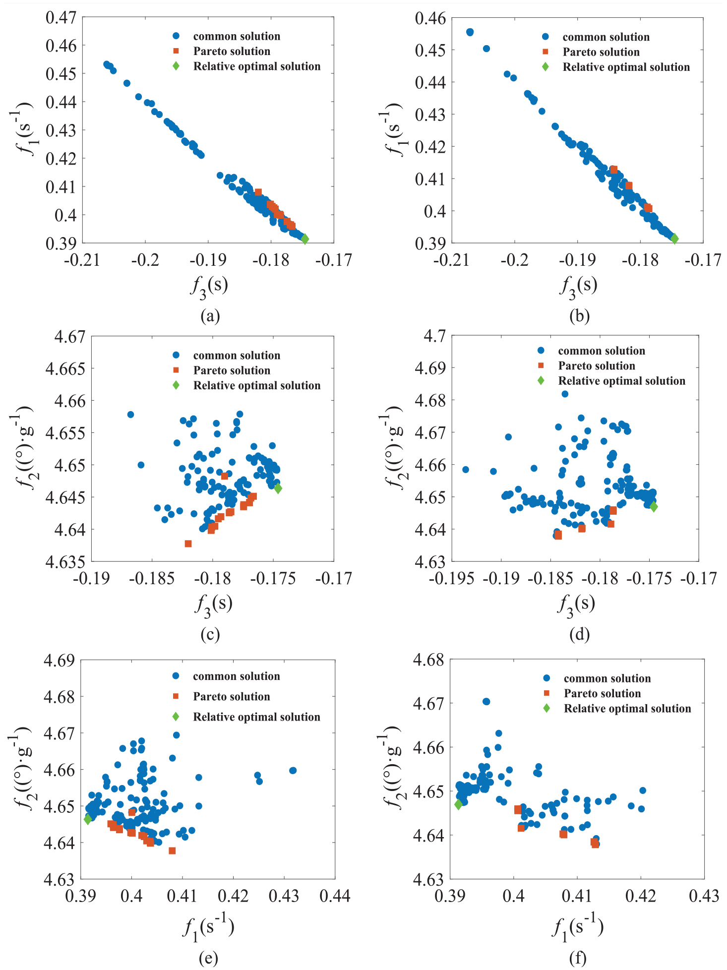
Pareto solution set: (a) f1 and f3 for the rigid model, (b) f1 and f3 for the rigid-flexible coupled model, (c) f1 and f2 for the rigid model, (d) f1 and f2 for the rigid-flexible coupled model, (e) f2 and f3 for the rigid model, and (f) f2 and f3 for the rigid-flexible coupled model.
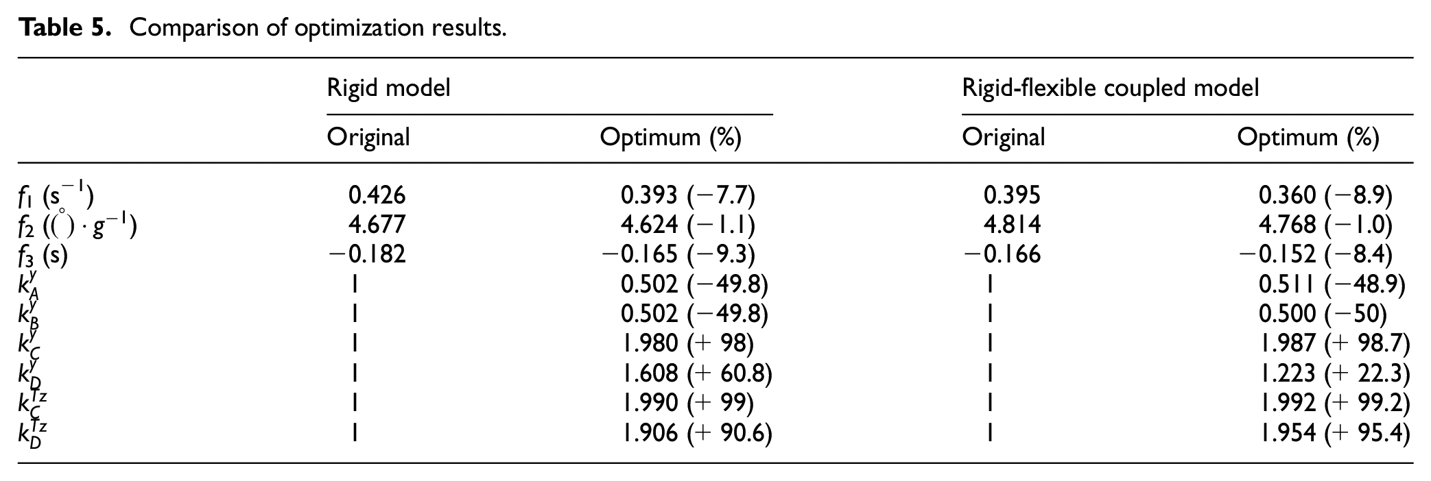
A comparison of the results before and after the optimization of the design variables and evaluation indicators is shown in Table 5. The values of the bushing stiffness refer to the measured values of a real vehicle, in which, considering the bushing as non-linear, the values of the bushing stiffness parameters in the optimized design are set as the scale factor.
Comparison of optimization results.
The optimized bushing stiffness was varied in the same proportion according to the value of the scaling factor, and the optimization results were verified by ADAMS dynamics simulation, and the variations and comparisons of f1, f2, and f3 before and after optimization of the rigid model and the rigid-flexible coupled model were obtained as shown in Figure 21.

Optimization comparison results: (a) yaw rate gain, (b) roll angle gain, and (c) delay time of acceleration.
Figure 21(a) compares the results before and after optimization for f1. The optimized f1 values are all decreased. However, the optimization results for the rigid-flexible coupled model are smaller compared to those of the rigid model.
Therefore, it is recommended to utilize the rigid-flexible coupled model for handling stability optimization to better approximate real-world vehicle behavior. Combining with Table 5, it can be observed that the optimized f1 values are reduced by 7.7% and 8.9%, respectively.
Figure 21(b) compares the results before and after optimization for f2. In the case of f2, the optimized values are reduced with similar magnitudes, and the difference between them is not significant. Combining with Table 5, it can be observed that the optimized f2 values are reduced by 1.1% and 1.0% respectively.
Figure 21(c) illustrates the comparison of results before and after optimization for f3. The optimized values for f3 are all reduced. Combining with Table 5, it can be observed that the optimized f3 values are reduced by 13.4% and 12.2% respectively.
The results show that the handling stability of the vehicle is improved.
Conclusion
This paper establishes the static equilibrium equations of the suspension and subframe system and the three-degree-of-freedom dynamics equations of the vehicle to theoretically explain the influence of the flexible front subframe on the handling stability of the vehicle, and establishes the rigid-flexible coupled model of the vehicle with flexible front subframe to analyses the specific influence of the flexible front subframe on the handling stability of the vehicle by means of the KC simulation of the suspension and sine swept steering input simulation. Then the NSGA-II algorithm is selected to optimize the rigidity of the bushing at the articulation of the flexible front subframe with the body and the suspension to optimize the handling stability characteristics of the whole vehicle. The specific conclusions are as follows:
The elastic deformation of the flexible front subframe changes the displacement of the bushing, resulting in a change in the reaction force exerted by the bushing on the suspension and in the displacement of the suspension, which in turn leads to a change in the KC characteristics of the suspension. The toe angle, camber angle, and roll stiffness of the suspension system are reduced.
The changes in suspension KC characteristics caused by the flexible front subframe will cause changes in front wheel roll steering angle
Sensitivity of front subframe bushing stiffness parameters on handling stability is analyzed. f1 and f3 are mainly affected by the translational stiffnesses
Using the NSGA-II algorithm for multi-objective optimization has effectively enhanced the vehicle’s handling stability. The optimization results demonstrate reductions of 7.7% and 8.9% for f1, 1.1% and 1.0% for f2, and 13.4% and 12.2% for f3, respectively. The optimization results of the rigid-flexible coupled model tend to obtain a better f1.
Footnotes
Appendix
Handling Editor: Sharmili Pandian
Declaration of conflicting interests
The author(s) declared no potential conflicts of interest with respect to the research, authorship, and/or publication of this article.
Funding
The author(s) disclosed receipt of the following financial support for the research, authorship, and/or publication of this article: This work was supported by the National Natural Science Foundation of China (NSFC) (No. 51965026). The authors are greatly appreciated for the financial support.