
Abstract
As an important load-bearing part of the automobile chassis, the subframe is connected to the body and suspension system, and it is of great significance to perform the research on subframe lightweighting to improve the ride comfort and handling stability of the automobile. In order to comprehensively reflect the influence of operating conditions on the subframe, and at the same time consider the performance requirements such as strength and modal, the lightweight design of the subframe was performed with the combination of multi-condition topology optimization and multi-objective optimization methods. A rigid-flexible coupled multibody dynamic model of the front suspension was constructed to extract the loads at each articulation point of the subframe under multiple working conditions. Furthermore, the subframe was optimized for multi-condition topology in combination with the compromise programing method. Subsequently, the subframe was reconstructed based on the topology optimization results and a radial basis function (RBF) neural network approximation model was constructed using the optimal Latin hypercube tests. Then, the NSGA-II algorithm was adopted for multi-objective optimization of the reconstructed subframe. The optimized front subframe satisfies the performance requirements with the first-order frequency increased by 4 Hz, a weight reduction of 2.5 kg, the lightweight rate reaches 9.1%.
Keywords
Introduction
With the emergence of global energy crisis and climate warming, automobile lightweighting has become a hot research topic. As a crucial part of the vehicle chassis, the subframe has a significant function in connecting the suspension with the body. Additionally, the suspension system, steering system, powertrain, etc. are usually connected to it. Therefore, the performance of the subframe, in terms of stiffness, modal, and other aspects, has a crucial impact on the comfort and stability of the whole vehicle. 1 In addition, under the guidance of the trend of vehicle lightweighting, it is also imperative to research subframe lightweighting.
In terms of structural lightweighting, based on the NSGA-II algorithm, Wang et al. 2 used Isight software to establish a multi-objective optimization model for wheels and a 29.42% weight reduction was achieved. Shreeshail et al. 3 optimized a subframe using the optimal criterion method to investigate the effects of subframe geometry and thickness variations on stresses and modes, the optimization results were effective and weight reduction was 9%. The conceptual design envelope of the subframe was established by Liao et al. 4 The ICM hybrid modeling method was introduced to obtain transmission paths of the conceptual design subframe, and the parametric model of the subframe was established based on the conceptual optimization results. NLPQL (Non-Linear Programing by Quadratic Lagrangian) algorithm was employed to optimize the shape of the parametric model of the subframe. The optimized structural performance meets the design requirements with a 10 Hz improvement in the first-order bending modal and a weight reduction of 1.84 kg. To improve the efficiency of structural optimization, an approximate model was typically constructed by collecting sample points through the design of experiments approach, and then a lightweight design of the structure was performed utilizing a certain algorithm based on the approximate model. The accuracy of the approximation model and the adoption of the algorithm directly affect the optimization results, so the fitting accuracy of the approximation model and the adaptability of the algorithm should be further investigated.
In terms of structural optimization research, Lan et al. 5 defined a comprehensive objective function, which regards the maximization of the vibration frequency and maximum static stiffness of the body structure. After determining the optimal weight coefficient for each loading condition, the topology optimization was carried out and the results showed that the dynamic frequency characteristics of the structure were enhanced. Lim et al. 6 proposed a method of parameterizing the spaceframe through its constituent unit cells, while a genetic algorithm was used for structure multi-objective optimization and the study showed the superiority of the periodic space framework. Li et al. 7 adopted the multi-material topology optimization algorithm to solve the flexibility minimization problem. It was shown that the optimization results were more accurate than the standard single-material topology optimization. Optimization of structural performance is not only an engineering problem but also involves various disciplinary fields such as material science, mechanical design, manufacturing engineering, and system dynamics. The comprehensive performance and durability reliability of optimized structures need to be further studied.
Multi-condition and multi-objective topology optimization studies are helpful for guiding the optimal design of subframes. Given the complex working environment of the automotive subframe, a rigid-flexible coupled multibody dynamics model of the front suspension was constructed to extract the loads at each articulation point under multiple operating conditions. Based on the compromise programing method, 8 a multi-condition topology optimization function was applied to minimize the structural strain energy, taking into account the multi-operating conditions. Then, a subframe parametric model was constructed based on the topology results. An RBF neural network approximation model was established through the optimal Latin hypercube tests, and the NSGA-II genetic algorithm was employed for multi-objective optimization. 9 The optimized subframe has achieved a significant lightweight effect while meeting the performance design requirements, providing a reference for the structural design of other products.
Multi-body dynamics model construction and finite element analysis of subframe
Multi-body dynamics model construction and load extraction
McPherson suspension is the object of this paper, Table 1 shows the key technical parameters of the suspension and some of the vehicle parameters. First, the subsystems of the front suspension system were abstracted and simplified. Then the simplified subsystems were modeled and assembled according to the connection relationship between the components. Finally, the corresponding physical parameters and mechanical properties were applied to the suspension system assembly model. Considering that the lateral stabilizer bar and subframe of the front suspension system are flexible bodies, a rigid-flexible coupled multi-body dynamic model of the front suspension was established. A rigid-flexible coupled multibody dynamics model of the front suspension, and the six-component force schematic of Table 3 are shown in Figure 1.
Parameters of the target vehicle.


A rigid-flexible coupled multibody dynamics model of the front suspension and six-component force schematic.
Combined with the multi-condition topology optimization method, the effects of typical operating conditions on the subframe structure were considered fully in the design and exploitation procedure of the subframe. In this paper, five typical working conditions, named forward braking, vertical impact, right steering, forward acceleration, and backward braking, were selected for static analysis. The specific acceleration values for each condition are shown in Table 2.
Acceleration parameter for static analysis conditions.

According to the working acceleration table and the technical parameters of the vehicle, the wheel loads were calculated and applied to the multibody dynamics model for simulation. Multi-body dynamic analysis was performed by the Adams/car software to obtain the load information for general operating conditions. Due to space constraints, Table 3 illustrates partial load information, where the six-component force schematic is shown in Figure 1.
Partial load information of the subframe under typical operating conditions.

Where LFL is the front mounting point of the left swing arm, LRR is the rear mounting point of the right swing arm, ARBL is the mounting point of the left stabilizer bar, and ER is the rear engine mounting point.
Finite element analysis of the front subframe
The subframe is welded from hydroformed tubes and press-formed steel plates, specifically made of S550MC cold-rolled high-strength steel. The material properties are shown in Table 4. Furthermore, the subframe is connected to the body by four axial vertical rubber bushings, and the geometric model of the front subframe is shown in Figure 2.
Subframe material parameters.


Geometric model of the front subframe.
Considering the structural complexity of the real subframe, the original geometric model was geometrically simplified and repaired for simulation calculations. The forward braking condition with large stresses on the subframe was selected for the mesh-independence verification, different sizes of elements were used to divide the mesh to investigate the maximum stress change, and the validation results are shown in Figure 3. In principle, the finer the meshing, the higher the accuracy of the solution results, but in the design and application of practical engineering, the sharp increase in the number of meshes will lead to a significant increase in the time of calculation. Therefore, to ensure the calculation accuracy and improve the simulation efficiency, the subframe was gridded employing quadrilateral and trilateral shell elements of 3 mm. The number of grids is about 170,000, with 3% trilateral cells, which all comply with the grid quality requirements. 10 In addition, weld seams and weld joints were simulated with rigid elements. Figure 4 shows the grid model of the front subframe.

Mesh-independent verification.

Grid model of the front subframe.
Modal analysis revealed that the first six-order non-rigid frequencies of the subframe were significantly higher than the excitation frequency typically experienced in general road conditions (typically below 25 Hz). Table 5 shows the modal frequencies, while Figure 5 illustrates the mode shapes for the first and second order, respectively. In addition, it is observed that the four-cylinder petrol engine, which is connected to the subframe, operates within a frequency range of 20–100 Hz (corresponding to engine speeds of 600–3000 rpm). The first-order frequency of the front subframe is 109.27 Hz, exceeding the resonance range of the ground and the engine.
The front sixth-order modal of the subframe.


The first two orders of non-rigid modal graphs: (a) the first-order modal graph and (b) the second-order modal graph.
Strength analysis of the original subframe is a prerequisite for carrying out topology optimization. The boundary conditions were set based on the load excitation values at each articulation point of the subframe, and the stress distribution under forward braking, vertical impact, right steering, forward acceleration, and backward braking conditions were solved, as shown in Figure 6. Under the forward braking, forward acceleration, and backward braking, the stresses were concentrated at the front end of the right longitudinal beam and near the swing arm mounting point, reaching maximum values of 394.295, 78.376, and 153.516 MPa, respectively. During the vertical impact, stress concentration was observed near the middle of the subframe rear cross beam, with a maximum stress of 135.743 MPa. Under the right steering, the subframe stress was concentrated near the connection between the rear cross beam and the left longitudinal beam, with a maximum stress of 192.965 MPa. Importantly, all these maximum stress values were below the yield limit of S550MC cold-rolled high-strength steel, ensuring that the subframe met the required strength performance standard.
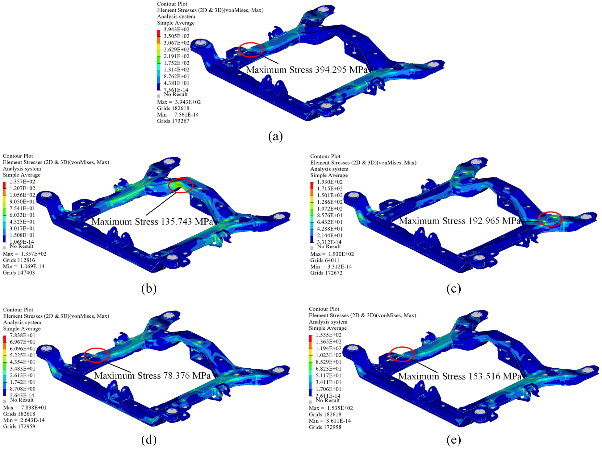
Stress cloud graphs of five typical loading conditions: (a) forward braking, (b) vertical impact, (c) right steering, (d) forward acceleration, and (e) backward braking.
Multi-condition optimization of the front subframe
According to the aforementioned results of the strength and modal analysis, the subframe stresses were predominantly concentrated at the mounting and connection points under various loading conditions. The maximum stress experienced by the subframe is 394.295 MPa, which was below the yield strength of the material. This indicates that there is potential for weight reduction without compromising structural integrity. To focus on the topology optimization, the main beams of the subframe were selected as the design domain, while other parts such as the swing arm and engine mounting bracket were classified as the non-design domain.
Multi-condition topology optimization
Topology optimization for maximizing stiffness aims to determine the optimal material distribution that enhances the structural stiffness, 11 and the optimized structure with maximum stiffness can provide better handling stability of the whole vehicle. However, it should be noted that different loading conditions usually result in different topology optimization structures. Therefore, the stiffness topology optimization problem under the above five typical conditions clearly belongs to multi-objective optimization. The variable density method (SIMP) was adopted for topology optimization, where the multi-objective topology optimization problem was transformed into a single-objective topology optimization problem 12 through the compromise programing method. In addition, the stiffness maximization problem is usually studied equivalently as a flexibility minimization problem, where the minimum structural flexibility that is, the minimum overall strain energy. The dynamic frequency of the subframe, which affects ride comfort, can be further constrained in the multi-objective optimization design of Section 3.1.
The optimization often involves multiple objectives in practical problems, and the compromise programing method performs multi-objective optimization by defining an ideal solution, which implies that each objective reaches its optimal value. A distance metric was employed to evaluate the distance between the current solution and the ideal solution, commonly used distance metrics include Euclidean distance and Manhattan distance. An optimal solution was found for each objective by minimizing the distance between the current solution and the ideal solution. Considering the different importance of each objective, a weight coefficient was introduced in the compromise programing method.
The main objective of this study was to minimize the structural strain energy denoted as

Where
Concerning the multi-condition topology optimization, the weight coefficient of each loading condition will directly affect the material distribution of the optimized subframe. In general, the setting of the weight coefficients depended on the characteristics and importance of each loading condition, the value was assigned based on a combination of literature 14 and experience. Considering the loaded acceleration as well as the importance of forward braking and vertical impact conditions, the weight coefficients were set to 0.25. The weight coefficients of the conditions are shown in Table 6.
Weighting values for typical working conditions.

To ensure the practical guidance of topology optimization results for subframe lightweight design, a left-right symmetry constraint was incorporated into the mathematical model. Additionally, the constrained maximum and minimum mesh member sizes were imposed at 15 and 30 mm, respectively, to guarantee homogeneity and manufacturability of the optimization results. 15
Multi-condition topology optimization is essentially a method to optimize the structural performance by adjusting the material distribution in the structure under the given constraints. The linear weighting method is utilized in OptiStruct software to deal with multi-objective topology optimization, but this method has the disadvantage of not ensuring that all Pareto optimal solutions are obtained for non-convex optimization. The compromise programing method (CPM) has been proven to overcome some of the drawbacks of the linear weighting method, and the CPM can find a solution on the non-convex region of the Pareto boundary. Fan et al. 16 used CPM with weights to optimize a three-section passenger car frame. Therefore, the custom equation provided in OptiStruct software was utilized to define the function C(ρ) of the CPM proposed in this paper, and then the defined function was set as the response, finally the response was used as the objective function for topology optimization. The specific optimization flow is shown in Figure 7.

Optimization flowchart for this study.
Reconstruction of the subframe
The lightweight design of the subframe was guided by the results of the multi-condition topology optimization to set up weight-saving holes and remove unnecessary materials. Figure 8 displays the topology optimization outcomes obtained after 12 iterations of the objective function, and the iteration history of the objective function

Multi-case topology optimization cloud diagram.

Iterative history of the objective function

Geometric model of the optimized subframe: (a) top view and (b) bottom view.
Multi-objective optimization of the front subframe
Establishment of an optimization mathematical model
With the functions of batch processing of the HyperMesh software, the model of the front subframe can be changed automatically according to the designated requirements. The intelligent lightweighting study of the front subframe in this paper focused on the beam thickness, the range of values for each variable was determined by the available design space of the front subframe, and the parametric model is shown in Figure 11. The parametric model was established based on the reconstructed subframe, laying the foundation for the subsequent multi-objective optimization design.

Parametric model of the reconstructed subframe.
The subframe was further optimized based on the parametric model, while the multi-objective optimization design requires to satisfy the performance requirements of multiple disciplines such as strength, modal, and fatigue durability. The optimization design of the subframe was performed by applying the Isight multi-objective optimization platform. The internal optimization problem of Isight software was characterized by parameters, focusing on the mass objective, so the weight factor of the mass objective was set to be 5, and other objectives were set to be 1. In addition, the strength and modal of the structure in the optimization process were constrained, and the specific optimization mathematical model is as follows:

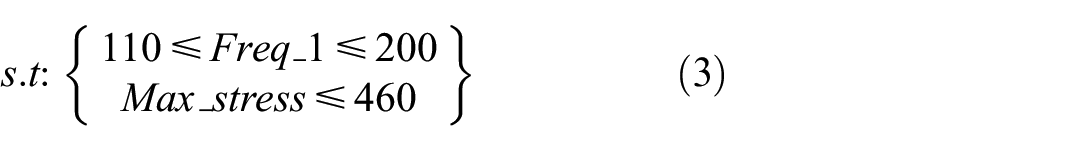

Where
Experimental design and development of an approximate model
Design of experiments (DOE) is the basis of structural optimization, with the following main roles: screening key design variables through sensitivity analysis, determining the optimal combination of design variable parameters, and obtaining sufficient samples to construct an approximate model. For the complex and numerous design variables, the sensitivity analysis can be applied to screen the key design variables and determine the optimal combination of design variables, which is conducive to reducing the computational intensity and improving the optimization efficiency. In this paper, only the thickness variables of the subframe will be optimized, and the computational intensity is moderate. Therefore, the sensitivity analysis was not performed and all eight thickness variables were taken as design variables. The optimal Latin hypercube test method with good comprehensive homogeneity, fewer samples, and strong space-filling ability was employed to collect 240 sample points. Each sample point typically includes a set of input parameters and their corresponding outputs parameters.
An approximation model was established to improve the efficiency of optimization. Furthermore, the RBF neural network model was used to fit the responses due to the high degree of nonlinearity between the design variables and the responses. To verify the accuracy of the established approximation model, 240 sample points were randomly divided into two parts, in which 180 sample points were used to construct the RBF approximation model and the remaining 60 sample points were used to verify the accuracy of the established approximation model.
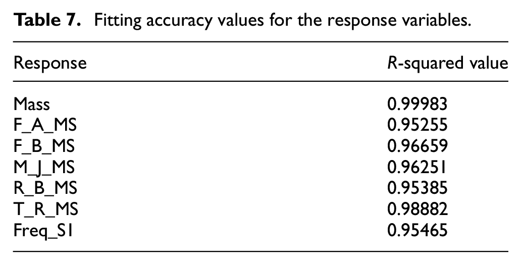
The R-squared coefficient was employed to evaluate the fitting accuracy of the approximate model. 17 Generally, the R-squared above 0.9 is acceptable, the closer to 1 the better. The accuracy of the RBF network approximation model was observed through the response fitness plots. Table 7 illustrates the fitting accuracy values of the front subframe response variables. The partial response fitness is displayed in Figure 12, where the horizontal coordinate is the predicted value, the vertical coordinate is the actual value, and the horizontal blue line represents the average response value.
Fitting accuracy values for the response variables.

Partial response variable fitting results for the approximate model: (a) Freq_S1, (b) Mass, (c) F_B_MS, and (d) M_J_MS.
Where Mass is the mass, F_A_MS is the maximum stress for forward acceleration condition, F_B_MS is the maximum stress for forward braking condition, M_J_MS is the maximum stress for vertical impact condition, R_B_MS is the maximum stress for backward braking condition, T_R_MS is the maximum stress for right steering condition, and Freq_S1 is the first order nonrigid frequency.
Multi-objective optimization based on approximate model
Since the NSGA-II algorithm has the advantages of low computational complexity, advanced and reasonable method of population arrangement, and high computational efficiency, this algorithm was chosen to optimize the front subframe. Define the optimization mathematical model of Section 3.1. The parameters of the NSGA-II algorithm were set as follows: the population size is 12, the total number of generations evolved is 20, the crossover probability is 0.9, the maximum number of computational failures permitted is 5, and the penalty value and target value for failed runs are both 1.0 × 1030.
The multi-objective optimization design based on the RBF network approximation model was completed after 241 iterations. The iterative curve of the mass response is shown in Figure 13, where the red points indicate the solution that does not satisfy the constraints, the blue points indicate the feasible solution and the green point indicates the recommended optimization solution. Therefore, the 235th optimized solution satisfied the design objectives best. The optimal solutions for variables are shown in Table 8.

Iteration curve of mass response.
Comparison of design variables before and after optimization.

Performance validation of the optimized subframe
Based on the fourth strength theory, the optimized subframe was calibrated for strength. Considering the subframe was subjected to larger stress under the forward braking condition, this condition was selected to verify its strength performance. The maximum stress of the subframe under the forward braking condition is 363.3 MPa, which is below the yield strength of the material. Evaluating the strength performance of the subframe by the safety factor

Optimized subframe stress cloud graphs: (a) forward braking and (b) right steering.
To verify the vibration frequency and stability of the subframe under the design requirements, carrying out modal analysis of the optimized subframe and determining the characteristics of the subframe under vibration such as the intrinsic frequency, vibration pattern, and amplitude. Figure 15 illustrates the first-order modal frequency of the optimized subframe, which was measured to be 113.20 Hz. Table 9 presents a comparison of the structural performance parameters before and after the optimization process. The modes of all orders were above the frequency of ground and engine excitation while meeting the design objectives.

First two orders of modal shapes after subframe optimization: (a) the first-order frequency graph and (b) the second-order frequency graph.
Performance parameters of the subframe before and after optimization.

The road surface produces excitation to the chassis suspension and body structure when the car is traveling on the actual road surface. The excitation will produce alternating cyclic stresses in the chassis and body structure, during which fatigue damage gradually accumulates. 18 For the constant amplitude loading cyclic process, when the stress in a component is higher than the fatigue limit of the corresponding material, the damage caused by one cycle is 1/N, and then the damage caused by n cycles is n/N. Due to the limitation of experimental conditions, a sinusoidal loading spectrum was employed in this paper to simulate the loading, which was a constant amplitude cyclic loading. The front subframe will be subjected to high-frequency stress alternations from ground and engine excitation during use. A high-cycle fatigue analysis was employed, which known as the stress-life (S-N) fatigue analysis method. In general, the stress and fatigue life of a component can be expressed by the Basquin equation as:

Where
Based on the stress-life (S-N) fatigue analysis method, the fatigue life analysis of the optimized subframe was performed in the Ansys/nCode software. The fatigue life analysis was performed by choosing the forward braking condition with higher stress, where the fatigue life of the optimized subframe is shown in Figure 16. The minimum fatigue life of the optimized subframe is 3.568 × 10⁵, which meets the safety life requirement (105).

Fatigue life of the optimized subframe.
Conclusion
A rigid-flexible coupled multi-body dynamic model of automobile front suspension was constructed to simulate typical working conditions and extract loads. Subsequently, the front subframe was optimized by combining with the compromise programing method, and the subframe was redesigned according to the topology results. Then, an RBF network approximation model was constructed employing the optimal Latin hypercube test method, and the NSGA-II algorithm was adopted to perform the multi-objective optimization design of the reconstructed subframe. The conclusions of the study are as follows:
(1) The structural performance was determined through strength and modal performance analysis, which provided a reference for the lightweight design of the subframe. The front subframe was optimized for multiple operating conditions by combining the compromise programing method, and the weight coefficients were set according to the characteristics and importance of each operating condition.
(2) The parametric model of the subframe can be coupled with other analysis software to automatically complete the optimization of the structure according to the design requirements, which can effectively shorten the lightweight design cycle and improve the competitiveness of the product. The RBF network approximation model was established by the optimal Latin hypercubic experimental test method, and the R-squared coefficients of each response were above 0.95. Therefore, the approximation model has high credibility.
(3) The NSGA-II algorithm was adopted for the multi-objective optimization design of the front subframe. The maximum stress of the optimized front subframe corresponds to the forward braking condition with a value of 363.3 MPa. The first-order nonrigid modal has been enhanced by 4 Hz, and the weight has been reduced by 2.5 kg, with a lightweighting rate of 9.1%. While achieving good lightweighting effects, it provides guidance for the structural optimization of other products.
Footnotes
Acknowledgements
The authors also acknowledge that many specialists’ guidance and comments on this article.
Handling Editor: Divyam Semwal
Declaration of conflicting interests
The author(s) declared no potential conflicts of interest with respect to the research, authorship, and/or publication of this article.
Funding
The author(s) disclosed receipt of the following financial support for the research, authorship, and/or publication of this article: This research was funded by the National Natural Science Foundation of China (Grant No. 52105260), Changzhou Sci & Tech Program (Grant No. CE20225049), Natural Science Research Project of Higher Education Institutions in Jiangsu Province (Grant No. 24KJA580003, 22KJA580002), Qinglan Engineering Project of Jiangsu Universities, Postgraduate Practice Innovation Program of Jiangsu University Of Technology (Grant No. XSJCX23_73).