
Abstract
Based on the velocity similarity theory, a test system for sediment wear flow around Francis turbine runner blades was established. The sediment wear test was carried out on the surface of Francis turbine runner blades with severe sediment wear before and after tungsten carbide spraying. The wear rate prediction model was established, and the effect of tungsten carbide spraying on the wear resistance of runner blades was analyzed. The results show that the serious wear position of Francis turbine runner blade by sediment appears in the head and tail, and the greater the load, the more serious the wear; after tungsten carbide spraying treatment, the sediment wear of runner blades is reduced by more than 90%, and the wear life is greatly improved. The sprayed tungsten carbide coating treatment is effective in reducing the effects of sediment wear.
Introduction
Hydraulic turbines operating on rivers with a lot of sediment are inevitably subject to the attack of sediment wear. Sediment wear will require overhaul and maintenance of the turbine in the case of mild abrasion, and will bring about major safety hazards and economic losses in the power station in the case of serious abrasion. Therefore, improving the anti-wear performance of hydraulic turbine can help to stabilize the operation of hydropower station, prolong the overhaul period and increase the economic benefits.
In recent years, scholars at home and abroad have paid more and more attention to the problems of sand water flow and sediment wear of hydraulic turbine. Noon and Kim 1 investigated the wear rate of Francis turbine affected by the concentration, size, and shape of sediment particles, and carried out numerical calculations by using ANSYS CFX, and compared and analyzed the results with the actual field data, which verified the accuracy of numerical calculations, and concluded the law of influence that the concentration, size, and shape of sand particles impact the wear rate. Acharya et al. 2 numerically analyzed the B-III HEP guide vane and observed the abrasion pattern originating from the leakage flow, the wear rate density, and the nature of the vortex. Chitrakar et al. 3 carried out a fully coupled Fluid-Structure Interaction (FSI) analysis using a multi-field solver to obtain the optimum angular distribution of the runner blades of a Francis turbine, provided that the efficiency and structural integrity of the turbine are not affected. Koirala et al.4–6 experimentally predicted the effect of wear in a 3GV vane grid system and found that the pressure on both sides of the blade and at the outlet of the blade increased with deeper wear, which in turn enhanced the flow friction leading to a further deepening of the wear, thus affecting the performance of the Francis turbine. Thapa et al.7,8 found that after the occurrence of abrasion in a low specific speed Francis turbine, the gap between the guide vanes and the panels increases and thus cross flow occurs further disturbing the velocity distribution at the inlet of the flow channel and the effect of leakage flow between the guide vanes and their walls was analyzed through experimental studies to determine the optimum turbine design. Based on the principle of velocity similarity, Pang et al. 9 designed a sediment wear test bench for Francis turbine runner with single runner bypass, obtained the motion mechanism of sand particles in the runner, and fitted the equation of sediment wear rate of Francis turbine runner in Minjiang river basin. Sugiyama et al. 10 found that the volume loss rate of all the materials tested for jet abrasion was essentially unchanged when the flow rate was less than 40 m/s and the attack angle was between 60° and 90°, and the volume loss was negatively correlated with the attack angle by investigating the relationship and the law of different materials as well as the surface hardness of the coatings and the attack angle with the abrasion. Ren et al. 11 compared and analyzed the basic properties as well as the corrosion and friction erosion characteristics of two coatings, alumina and tungsten carbide coatings. Maharajan et al. 12 used a thermal coating technique of plasma spraying, where 50 μm of tungsten carbide was sprayed in the form of powder on the surface of an austenitic stainless steel (SS316), to form a tungsten carbide coating and to improve the performance of the surface topography. Casteletti et al. 13 used HVOF (High Velocity Oxygen Fuel) process to prepare tungsten carbide coatings and the coatings from this thermal spray process were characterized by high erosion and corrosion resistance. Knapp and Nitta 14 studied the surface degradation of tungsten carbide coatings by fine grain abrasion. Grinding of 0.15 mm thermal spray coatings, using diamond polishing and selecting high quality bonding agents can improve the wear performance of tungsten carbide coatings by fine grain abrasives. Schwarz et al. 15 studied the wear performance of tungsten carbide reinforced and non-reinforced coatings, wear tests and scratch tests were performed on the coatings. Shchegolev et al. 16 investigated the process, structure, and properties of a new Fe-Cr-C abrasion-resistant coatings, introduced tungsten carbide to improve the original coatings to increase the coatings abrasion resistance.
To improve wear prediction and account for the pit morphology on overflow walls caused by wear, Messa and Malavasi 17 proposed a wear prediction model based on the Eulerian-Eulerian model for particle trajectories and wear morphology. Chen et al. 18 introduced a stochastic rebound model for predicting both the wear rate and wear morphology of a tee. Mansouri et al. 19 employed computational fluid dynamics (CFD) simulations to characterize the velocity, angle, and frequency of particle impacts at specific locations within a specimen. They then correlated this particle impact data with measured wear depth to derive wear equations for impact wear experiments. Due to the small size of the clearance, the internal water flow is mainly a jet, which can lead to the SE at the wall, increasing clearance leakage and reducing unit efficiency finally. 20 Shen et al., 21 focusing on a doublesuction centrifugal pump operating in rivers with high sediment concentrations, conducted experiments using a multi-layer coating method to study the patterns of sediment erosion on its blades during normal operation. Through this function, the development of erosion area on the blades during long-term operation can be effectively predicted. By using Euler-Lagrange method and erosion model, Wang et al. 22 studied the influence of sand mixing characteristics on the erosion characteristics of centrifugal pump flow wall. Khullar et al. 23 used the erosion-induced geometric deformation method to study the erosion sensitivity of the guide vane and the intake plate of a Francis turbine. Based on the velocity triangle change in the guide apparatus and the flow similarity principle, a flow-around wear test device for the guide apparatus of the reaction turbine was designed. 24
At the same time, the influence of hydraulic turbine mechanical structure materials and sediment particles on wear is also gradually developed. Rehan et al. 25 used five Pelton buckets made of aluminum, carbon steel, stainless steel, polylactic acid (PLA), and acrylonitrile butadiene styrene (ABS) to perform erosion experiments under two-phase, solid-liquid flow conditions. Yang et al. 26 used a rotating disk device to conduct cavitation erosion and powder erosion tests on three materials (06Cr16Ni5Mo, Q355B, 06Cr20Ni11) at different sand content and impact velocity, and observed the cavitation erosion and powder corrosion characteristics of the materials by scanning electron microscopy (SEM). Li et al. 27 used numerical simulation to study the sediment erosion characteristics of a full-size impact turbine runner under rated operating conditions. The main purpose is to study the influence of different sediment content (0.6%, 0.45%, 0.15%) and diameter (1, 0.1, 0.01, 0.001 mm) on the runner of impact turbine. Padhy and Saini 28 determined that the size of sediment particles played a crucial role in material wear and damage through experimental investigations.
This paper focuses on the experimental study of sediment wear of tungsten carbide spray treatment before and after the runner blade of Francis turbine in Minjiang river basin Yingxiuwan power station. According to the data of sediment wear test results, the formula of turbine runner blade abrasion rate is determined, and the abrasion situation of tungsten carbide sprayed runner blade and uncoated blade is analyzed, and the life span of runner blade is predicted, so as to put forward the operation strategy of the power station.
Basic parameters of hydraulic turbine and power station
Yingxiuwan power station is located in the Minjiang river basin in the eastern part of the Tibetan Plateau of China, which has no reservoir to store water and adopts the runoff diversion method. The basic parameters of hydraulic turbine are shown in Table 1.
Basic design parameters of hydraulic turbine.
The landscape of the Minjiang river basin is mostly characterized by high mountains and valleys, with frequent geological disasters such as long-term earthquakes and landslides. After the Wenchuan earthquake and the natural disaster of huge mudslide in 2008 and 2010, the sand transport of Minjiang river basin rivers increased dramatically, with a 76% increase in sand content compared to the past, and the sediment particles in the water flow are hard and complex. 9 The power stations operating on the Minjiang river have been severely damaged by sediment wear, resulting in lower operational stability and shorter service life of the units. The sand passing through hydro-turbine parameters of the power station are shown in Table 2.
Sediment parameters.
Sediment wear test conditions and parameters are shown in Table 3.
Sediment wear test parameters.

Test method for sediment wear of hydraulic turbines
Test principle
Due to the limitation of test conditions, it is not possible to conduct the test on the real-size hydraulic turbine. Therefore, the bypassing test method is considered to be used to carry out the bypassing wear test of a single flow channel under a certain system pressure, based on the numerical calculation results of the sand water flow of the test condition, and the specimens including the runner blades are extracted from the sand water flow line according to the principle of similarity of the flow conditions. According to the relevant research results, 24 the wear of sediment particles on the solid wall is mainly affected by the sediment velocity and sediment concentration. It is ensured that the design of the test device and the real device maintain kinematic and geometric similarity. The numerical calculation method is used to compare and analyze the velocity and concentration distribution near the wall of the test device and the real device. The design of the test model is kept similar to the flow conditions of the real overflow channel, so as to ensure that the test results coincide with the real results.
The Superview W1 optical 3D surface profiler (which has an accuracy of 0.1 μm) was utilized to read the profile heights Zb and Zr of the surface test at the same location before and after the test of the test piece, and the difference, that is, ΔZ = Zb−Zr, is the depth of wear of the test piece. Figure 1(a) shows an example of the test data at the test position of a runner blade specimen, with the surface heights before and after wear as black and red curves, respectively. Due to the test process along the leaf height direction, the runner blade specimen upper and lower end surfaces of the box side wall effect exists, in order to avoid the test section of the box in the sand water flow on the runner blade specimen wear effects, to avoid affecting the accuracy of the measurement data. In order to get more accurate wear depth of the runner blade specimen, the surface measurement value near the height of 1/2 runner blade specimen is taken, that is, the range of 40–60 mm (40%–60% of the blade height) in Figure 1(b).

Extraction method of the surface wear depth of the specimen: (a) relative depth of reference surface and (b) wear loss.
Test system
The sediment wear test system consists of a test setup, a dynamic system, a sand-water mixing system, and a cooling pool, as shown in Figures 2 and 3. The system has a maximum power of 630 kW, a maximum head of 376 m water column, and a maximum flow rate of 482 m3/h. The cooling pool adopts a serpentine pipe to extract underground water for cooling. The river sand particles of the power station are collected, and the sand and water are proportioned according to the test concentration, and the sand-water mixing system uses the stir method to complete the uniform mixing of sand and water. 29

Schematic diagram of the sediment wear test system.

Physical drawing of the test device system.
Design and fabrication of specimen and work piece
Design of experimental blade
According to the numerical calculation results of the sand water flow inside the hydraulic turbine of this power station, the relative velocity of the hydraulic turbine runner blade near the band area is large, and the local sediment concentration is also high, and based on the hydraulic turbine sediment wear mechanism and modeling, it can be presumed that its abrasion will also be more serious near the band area. In order to simplify the sediment wear working device and specimen, this study takes the flow surface of the runner near the lower ring as the focus of the study, as shown in Figure 4(a), based on the results of numerical calculations of the flow and the extraction of the sand water flow lines of the hydraulic turbine runner blades, as shown in Figure 4(b). According to the principle of geometric similarity and velocity similarity, the sand flow field characteristics of the test device and the real machine are ensured to be consistent. 30

The schematic diagram of the band surface and the sand flow line of the runner: (a) runner near the band surface and (b) runner blade single channel sand flow line.
According to the conditions of the test system, especially the dynamic system, the test work section and blade specimens are made according to the single-flow channel design, and the runner blade sand water flow line extension is designed as the test blade, and the bone line extension of its neighboring blade is designed as the wall of the test work section flow channel, and the inlet and outlet area ratio of the test section is the same as the inlet and outlet area ratio of the real machine runner. Single line design of the test section for two conditions of this runner blade sediment wear test, as shown in Figure 5.

Dimensional drawing of the test section of the runner blade: (a) P = 11.8 MW and (b) P = 42.8 MW.
Test blade fabrication and tungsten carbide spraying treatment on blade surface
The runner blade specimen is made by CNC machining process, the length of the blade specimen is 272 mm, and the base material is ZG06Cr13Ni4Mo alloy steel.
Tungsten carbide spraying is a common metal surface coating technology that improves the hardness, erosion, and corrosion resistance of materials. 31 The tungsten carbide spraying process includes surface treatment, spray preparation, spray operation, drying, curing, and inspection. When spraying tungsten carbide on hydraulic turbine runner blades, the spray quality and coating thickness need to be controlled to ensure the coating quality and performance, and to ensure that the tungsten carbide spraying technology will not affect the flow characteristics of the flow field inside the runner. The molecular structure and physical form of tungsten carbide are shown in Figure 6.

Tungsten carbide physical morphology and molecular structure: (a) tungsten carbide molecular structure and (b) tungsten carbide powder.
Tungsten carbide is a compound composed of tungsten and carbon, with molecular formula WC and molecular weight 195.85. The basic form is black hexagonal crystal with metallic luster, hardness similar to that of diamond, and is a good conductor of electricity and heat. 32 The parameters of physical properties of tungsten carbide are shown in Table 4.
Physical properties of tungsten carbide.
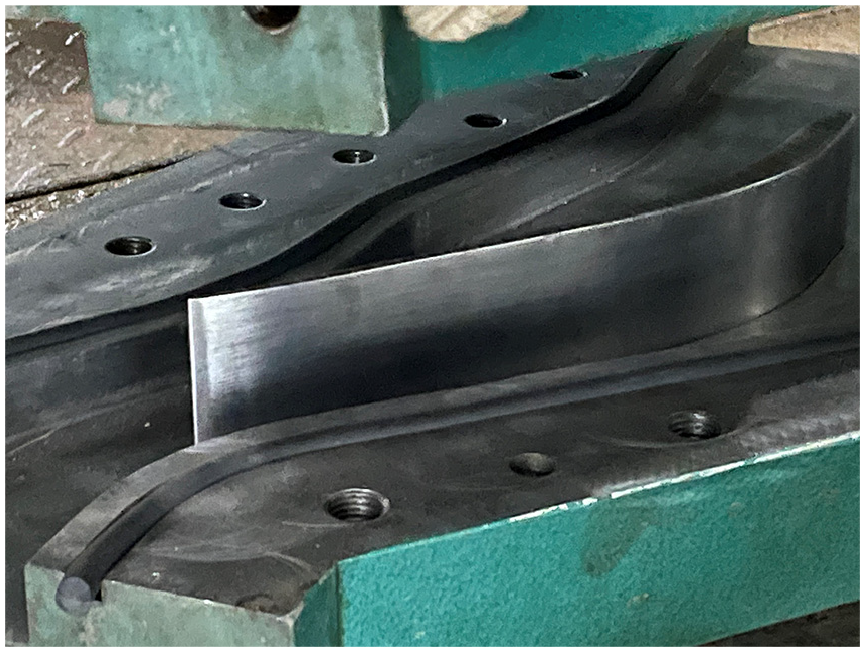
The author sent the runner blade test specimen to the metal material processing factory during the study, and required the processing factory to uniformly spray the surface of the blade test specimen with a thickness of 0.3 mm. Tungsten carbide sprayed specimen (after surface polishing), as shown in Figure 7.

Runner blade specimen after tungsten carbide spraying.
Design and production of experimental work
According to the single line diagram design test working section, as shown in Figure 8. The material of the is made of Q345B carbon steel, which is produced by CNC machining process, and the installation slots of the runner blade specimen and the test section are reserved, and the depth of the installation slots are 15 and 5 mm, with clearance fit.
Test working section.
Runner blade sediment wear test and result analysis
Test conditions and analysis of results
Sediment for testing was collected at Yingxiuwan power station, and sediment wear test was carried out on hydraulic turbine runner blades with sediment concentration of 3.27 kg/m3 and two guide openings (outputs) operating conditions. The materials were ZG06Cr13Ni4Mo alloy steel and tungsten carbide specimen with 0.3 mm thickness sprayed on the surface, and the test wear time was 96 h. and a total of 43 lines were tested on the front and back of a set of experimental blades.
The comparison of the runner blades sprayed with tungsten carbide before and after the wear of the specimens under the operating condition of P = 42.8 MW is shown in Figure 9.

Comparison diagram of runner blade before and after test under P = 42.8 MW working condition: (a) before wear test (suction side), (b) after wear test (suction side), (c) before wear test (pressure side), and (d) after wear test (pressure side).
The suction side and pressure side wear loss of the runner blade specimens for two conditions were obtained using Superview W1 optical 3D surface profiler. The total wear on the head and tail of the tungsten carbide sprayed runner blade specimen is more serious, and the wear loss shows a trend of decreasing and then increasing, in which the maximum wear loss is about 4.5 μm on the tail, 4.1 μm on the head, and the wear loss in the middle part is relatively small, with the minimum wear loss of about 2.4 μm. The combined wear of the pressure and suction sides of a data line equals the total wear for that line. The maximum total wear on the tail of the specimen is about 8.2 μm, and the total wear on the head is about 7.4 μm, and the smallest total wear loss in the middle of the specimen was about 5.0 μm, as shown in Figure 10. Through data analysis and processing, the erosion loss in the chordwise direction of different airfoils were obtained, and the relative velocities and local sediment volume fractions of the pressure side and suction side of the blade specimens were obtained from numerical calculations and test data. The average and standard deviation of the wear amount at each point were processed based on three sets of measured results, and error lines were added in Figure 10.

Runner blade chord erosion: (a) P = 11.4 MW and (b) P = 42.8 MW.
Establishment of wear rate prediction model
The expression for the sediment wear rate of the turbine overflow components is given as:

Where: E is the wear rate (wear depth of the surface material on flow passage components in unit time), μm/h; ks and km are the sand particle characteristics and the material characteristic coefficients of the turbine flow passage components, respectively; k0 is the coefficient of influence of the attack angle of the sand particles; ϕp is the volume fraction of the localized sediments on the surface of the turbine flow passage components; the index m is 1 in general; W is the relative velocity of the sand on the surface of flow passage components, m/s; and n is the velocity index.
For a practical study of the hydropower station, the turbine overboard sand characteristics, blade material characteristics are determined, also, can make k = kskm, in addition, k0 can be expressed by a polynomial attack angle (sand attack on the surface of the overboard components) function, or, k0 = f(α) = Aα + Bα2 +Cα3 + Dα4 + Eα5 + Fα6, A, B, C, D, E, F are coefficients.
In this way, the expression for the sediment wear rate of the turbine flow passage components can be further written as:

With the results of the sediment wear rate test, and based on the results of numerical calculations of sand water flow in the hydraulic turbine, it is possible to rate the turbine wear rate formula (2) based on the data of the wear rate distribution, the distribution of the sand velocity characteristics (magnitude and direction), and the fraction of localized concentration.
According to the results of the hydropower station turbine sediment wear test, combined with the results of sand water flow calculations, a runner blade wear rate prediction model can be established. The parameters of the wear experience formula are shown in Table 5.
The parameters of the wear experience formula.
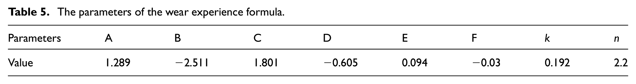
Modeling of wear rate prediction after tungsten carbide sprayed treatment on hydraulic turbine runner blade surface:

Where: α is the impact Angle of sediment particle velocity, °.
Comparative analysis of the wear of sprayed and unsprayed runner
Figure 11 shows the comparative analysis of the wear loss of the runner blade surface with and without tungsten carbide spraying treatment under two working conditions. It can be found that the maximum wear loss of the unsprayed runner blade specimen is 60 μm, while the maximum wear loss of the sprayed runner blade specimen is only 4.5 μm under the working condition of P = 11.4 MW. Under the working condition of P = 42.8 MW, the maximum wear loss of the unsprayed runner blade specimen is 90 μm, while the maximum wear loss of the sprayed runner blade specimen is only 8.2 μm, which shows that the anti-wear ability of the sprayed specimen is greatly improved. It shows that the wear resistance of the specimen after spraying treatment is greatly improved.

Comparison of unsprayed runner blades with sprayed wear of runner blades: (a) P = 11.4 MW and (b) P = 42.8 MW.
According to the hydraulic turbine sediment wear overhaul and maintenance industry standards and test results of the tungsten carbide spray treatment before and after the runner wear life prediction, of course, we should consider that when the hydraulic turbine after a long period of operation, the blade indicates that the protective layer of tungsten carbide spraying is worn out, then it will wear out the base material of the blade, and in the prediction of the wear life of the hydraulic turbine, the wear of the base material should be taken into account. The wear rate of the runner blade is obtained by formula 3, and the operational life of the blade is obtained by comprehensive fitting according to the sediment concentration in different seasons of the actual hydrological data of the power station. The results show that spraying tungsten carbide on the surface of runner blade can effectively improve the abrasion resistance and operating life of runner blade. The results of this study found that tungsten carbide spraying can extend the operating hours of the runner by about 16.5 months under low output conditions and about 8.8 months under high output conditions. The comparative life analysis of the runner blade surface with and without tungsten carbide spraying treatment under two working conditions is shown in Figure 12.

Runner blade unsprayed versus runner blade sprayed life: (a) P = 11.4 MW and (b) P = 42.8 MW.
Conclusion
The blade head is mainly affected by impact wear, while the blade surface is mainly affected by cutting wear. The serious position of the runner blades subject to sediment wear occurs in the head and tail, and the larger the load condition, the more serious the abrasion.
The experimental data and the numerical simulation results of sand-water flow obtained the parameters of the empirical formula of hydraulic machinery sediment wear, and the wear formula of the basin was obtained by nonlinear fitting method.
The wear formula can judge the wear depth of the runner blade when it is subjected to the cutting wear of sand particles, so as to predict the wear life of the runner blade. Tungsten carbide spraying technology can ensure the anti-wear performance of the runner blade is improved, and the working hours of the runner can be extended by about 16.5 months under the low-output condition, and the working hours of the runner can be extended by about 8.8 months under the high-output condition. Therefore, spraying tungsten carbide coating can effectively reduce the effect of sediment wear.
Footnotes
Handling Editor: Aarthy Esakkiappan
Declaration of conflicting interests
The author(s) declared no potential conflicts of interest with respect to the research, authorship, and/or publication of this article.
Funding
The author(s) disclosed receipt of the following financial support for the research, authorship, and/or publication of this article: This study was supported by the National Natural Science Foundation of China-Regional Innovation and Development Joint Fund Project, “Air Doping Corrosion Reduction Mechanism and Control of Cavitation and Wear Coupled Damage of Pump Turbines in High Altitude Areas” (Project No. U23A20669).