
Abstract
The primary advantage of metal injection molding (MIM) is that it can be used to mass-produce complex metal products; however, it requires a few secondary processes. Metal additive manufacturing (MAM) technology is maturing, and conformal cooling channels have been widely used in injection molding. However, plastic injection molding remains the topic most often discussed in the literature. The present study combined MIM with MAM to explore the effect of conformal cooling channels on green parts and molds, which is the novelty of this study. In the design stage, the benefits of the conformal cooling channels were evaluated using the injection molding simulation software Moldex3D. The results revealed that the mold preheating time required when conformal cooling channels were used was 92.8% shorter than that required when conventional cooling channels were used. This study used three-dimensional printing of metal to fabricate the die cores and cavities for conformal cooling channels, and trial runs were conducted to compare the conformal cooling channels with conventional cooling channels. Infrared thermographic imaging revealed that the conformal cooling channels improved cavity temperature uniformity by 15.46% and core temperature uniformity by 3.49%; these improvements are crucial because the quality of green parts is strongly affected by the control of temperature in the mold. When a suitable coolant temperature was applied, the conformal cooling channels removed heat more effectively, resulting in a lower mold temperature and shorter cooling time. During an actual trial run, the cooling efficiency of the adopted conformal cooling channel mold was higher than that of the adopted conventional mold. In addition, the production of green parts remained smooth operation. The dimensions of the green parts obtained using the conformal cooling channels were comparable to those obtained using the conventional cooling channels, which proved that the conformal cooling channel mold yielded green parts with similar dimensional accuracy while reducing the cycle time.
Introduction
In injection molding, the cooling channel directly affects the rate at which the mold cools and the distribution of temperature in the plastic within the mold cavity. When a conventional mold is used, a drilling process is employed to create a linear channel, and achieving a uniform temperature distribution during the cooling stage is difficult. This study adopted computer-aided engineering to design conformal cooling channels and employed metal additive manufacturing (MAM) to fabricate a die core and cavity. The designed conformal cooling channels were expected to stabilize the flow of metal powders distributed in melt polymers and to achieve a uniform powder concentration distribution. In addition, the effect of the conformal cooling channels on bolt catches in metal injection molding (MIM) was explored. The motivation for this study was threefold: to accelerate mold design and fabrication, to improve the temperature uniformity of die cores and cavities, and to reduce the cycle time of injection molding.
In the 2010s, the annual growth rate of global MIM sales, based on the tonnage of powder consumed, was approximately 20%. 1 The global MIM market was worth approximately USD 2.1 billion in 2015 and was anticipated to grow from 2016 to 2025 at a compound annual growth rate of 11.9%. 2 In 2014, 40% of metal powders in the North American market were supplied to the arms industry. MIM can produce components with complex and near-net-shape exteriors. Therefore, MIM technology has the advantages of high accuracy and low cost in the manufacturing of weapon parts, particularly firearm components weighing under 50 g. The MIM process is followed by a secondary process of hot isostatic pressing 3 to fully densify the product. The ratio of metal powder volume to binder volume for MIM feedstock is 60/40; the material properties of such feedstock, particularly its viscosity and thermal conductivity, are thus difficult to measure. Moreover, the rheological properties of the feedstock are complex; the Cross William–Landel–Ferry with Herschel–Bulkley model 4 must be employed to determine its flow behavior during the filling stage and to predict the powder–binder separation region. 5
Technological advances have been achieved in the three-dimensional (3D) printing of metals, and conformal cooling channels that can be created through 3D printing are proving crucial to the development of precision molds, although most molds used in manufacturing and academia are employed for plastic injection molding. In plastic injection molding, conformal cooling channels lead to smaller mold temperature heterogeneity, less warpage, and a shorter cycle time than do conventional cooling channels organized in a linear configuration. A reduction of up to 50% in cooling time can result in an increase of up to 20% in productivity.6–8 Additive manufacturing (AM) involves layer-by-layer formation and is different from conventional subtractive manufacturing. AM can thus produce finished objects with a complex shape. Therefore, MAM is considered to be the best technology for producing conformal cooling channels. The current study evaluated whether applying conformal cooling channels in MIM mold design has the same advantages as it does in plastic injection molding and further explored the effect of mold temperature on green parts.
Conformal cooling channels are typically meandering and located close to the mold wall. The guideline 9 provides a design specification for the layout of conformal cooling channels. The key purpose of conformal cooling channels is to improve cooling efficiency. Die cores and cavities are mainly manufactured using MAM. Electro-Optical Systems GmbH developed the first direct metal laser sintering (DMLS) machine for metal 3D printers in 1994 and commercialized it in 1995. 10 In 2000, Sachs et al. 11 noted that conventional baffles and bubbler cooling channels make the internal structure of core insert fragile, and they used 3D printing to fabricate conformal cooling channels, which enabled more precise control of the mold’s temperature than did conventional cooling channels. Conformal cooling channels can also stabilize a mold’s temperature within a short period. In 2010, Ilyas et al. 12 used indirect selective laser sintering to fabricate a die core and cavity with conformal cooling channels and employed the cut-out volume technique to remove excess metal powder to ensure that the conformal cooling channels were smooth. In addition, injection molding simulation software (Moldex3D) was used in the mold design stage to ensure an appropriate channel design, which ensured high productivity and relatively low energy usage. Ahn et al. 13 combined laser-aided direct metal tooling processes with computer-aided engineering analysis to fabricate molds with conformal cooling channels and investigated the molding conditions of products with different cooling times. Their results revealed that in addition to reducing cooling time, use of conformal cooling channels rather than linear cooling channels resulted in a more uniform temperature distribution.
With the development of Industry 4.0, sensors are being used to collect real-time temperature data in the cavity of molds containing MAM-fabricated conformal cooling channels. 14 Moreover, alternative materials such as silicone rubber and epoxy resin were used in one study to fabricate a mold with conformal cooling channels, and other technologies associated with Industry 4.0 were reviewed. 15 The Reynolds number is a crucial index of flow behavior in conformal cooling channels, and optimizing the Reynolds number is recommended for maintaining the coolant in a turbulent state, which results in favorable heat transfer and cooling efficiency. 16
The aforementioned studies6–8,11–14 have discussed the application of conformal cooling channels in thin plastic shell parts. To the best of our knowledge, the present study is the first to investigate the relationship between conformal cooling channels and MIM, and the molded piece was the thick component under MIM processes. This study demonstrated how the temperature uniformity of thick green parts can be improved through the appropriate design of conformal cooling channels. By performing injection molding simulations and actual trial runs, this study compared the effects of conformal cooling channels and conventional cooling channels on mold temperature; cycle time; and the temperature, dimensions, and shape of green parts. The results of this study are expected to be useful in the MIM industry, and the analysis and design techniques outlined in this paper for the fabrication of conformal cooling channels are expected to have considerable benefits in terms of reducing the cooling time and improving manufacturing quality.
Injection molding simulations
Conventional and conformal cooling channels
The two-plate mold used in this study had a one-mold, four-cavity design. The Reynolds number distribution inside the cooling channel is directly related to a cooling channel’s diameter. The diameter of the conventional cooling channels considered in this study was 8 mm to achieve turbulent flow. Because mechanisms such as ejector pins, angle pins, and slides were located around the mold cavity, to stay away from these mechanisms, the conventional cooling channels could only enter and exit in a straight line far from the mold cavity (Figure 1). The runner and cavity of the adopted conformal cooling channel mold were exactly the same as those of the adopted conventional mold—only the cooling channels were different (Figure 2). The channel design was modified on the basis of the results of injection molding simulations, and the minimum distance between the channels or between the channel and mold wall had to adhere to the channel design specifications of laser AM technology.9,17 The diameter of the cooling channels at the mold base and core cavity was 8 and 3 mm, respectively. An O-ring seal had to be installed at the junction of the two different-diameter channels. Once the design was completed, a die core and cavity were manufactured through 3D metal printing; the complete mold assembly is shown in Figure 3.

Configuration of conventional cooling channels inside a mold. The electronic Supplemental Material includes an engineering drawing showing the detailed mold dimensions.

Configuration of conformal cooling channels inside a mold. The blue and purple components represent the conformal cooling channels and runner–gate system, respectively.
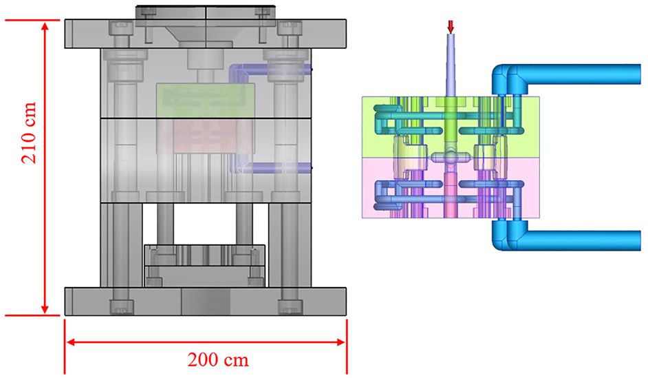
Conformal cooling channel mold. The green and pink components represent the cavity of the fixed plate and the core of the movable plate, respectively.
Process parameter setting
The shape of conformal cooling channels is relatively complex, and laser AM is expensive. Therefore, injection mold simulations were employed to assist with mold design and process parameter tuning to reduce costs. In Moldex3D, the machine mode was selected for setting the injection mold conditions; the melt temperature was 118°C, the initial mold temperature and ambient temperature were both 20°C, the coolant temperature was 36°C, and the mold preheating time was 10 min. Because the temperature of the coolant was higher than the mold’s initial temperature and ambient temperature, the cooling channels had a cooling effect on the mold in the filling and packing stages but heated the mold in the cooling and mold-opening stages. The injection speed was 30 cm3/s, and the injection pressure applied was 930 and 1100 bar for two steps, respectively. The packing stage was divided into four steps, with respective step times of 1.0, 1.0, 1.5, and 0.3 s (total time of 3.8 s), and the respective pressure applied during these steps was 800, 400, 250, and 50 bar. Because this study wished to strictly test the conformal cooling channels’ cooling efficiency, the cooling time settings differed for the two cooling channel molds (8 and 5 s for the conventional and conformal cooling channels, respectively).
Experiment
Material
The feedstock used in this study was created by kneading and granulating SKD11 metal powder (Sandvik AB, Sweden) and a wax-based binder; the binder contained polyethylene, stearic acid, and paraffin wax. The weight-fraction concentration of the metal powder was 93.6 wt%. The measured viscosity and pressure-specific volume–temperature relationship of the feedstock 18 had to be input as material properties in the injection mold simulations.
Facility
The injection molding machine used in this experiment was Arburg Allrounder 270C Golden Edition (Arburg GmbH Co., Lossburg, Germany), and the JSW-1012E controller (Jieshen Machinery Co., Ltd, Taipei, Taiwan) was used for heating and maintaining the mold temperature. The temperature distribution on a mold’s surface was measured using the FLIR A615 infrared thermography camera (FLIR Systems, Inc., OR, USA). Computed tomography (CT) scans were performed using the TomoScope XS (Werth Messtechnik GmbH, Germany) X-ray inspection instrument under a voltage of 145 kV and a magnification of 25×. The scans had high resolution, having an average of 2940 × 2304 pixels and a voxel size of 50 µm.
AM of a core and cavity with conformal cooling channels
In this study, a die core and cavity with conformal cooling channels were fabricated through MAM. The adopted 3D printing machine was the Sodick OPM250L instrument (Sodick Co., Ltd., Kanagawa, Japan), which performed DMLS and emitted high-energy laser radiation through ytterbium fibers on SS420J2 (stainless steel) powder. The metal powder was heated and sintered for solidification and formation under a laser power of 400 W, a laser scanning speed of 700 mm/s, and a laser spot diameter of 0.1 mm. After the die core and cavity were 3D-printed, low-temperature secondary tempering was performed to eliminate residual stress, and a hardness of the die core and cavity reached HRC 51 ± 1. Because the surfaces of the die core and cavity were still rough (Figure 4), a 0.5-mm-spare space was reserved for cutting, electric discharge machining, and grinding. Finally, computer numerical control (CNC) was employed to achieve a surface roughness of Ra < 0.8 μm. Figure 5 depicts a flowchart of the methods adopted in the present study.

Die core and cavity of the conformal cooling channels manufactured through MAM. The AM-fabricated core and cavity must be heat-treated through tempering to eliminate residual stress.

Flowchart of the mold design and manufacturing process for MIM green parts.
Size measurement of green parts
The dimensional differences (in the X-, Y-, and Z-direction) in the green parts produced with the conventional and conformal cooling channel molds were determined. In principle, the three dimensions of the two mold cavities should be identical (Figure 6). The product investigated in this study was a bolt catch. The dimensions of its green parts formed by these two types of molds were measured manually by using a JTVMS-2515 (Dongguan Jaten Precision Instrument Co., Ltd, China) 2.5D noncontact vision measuring machine to test the accuracy of the dimensions.

Mold cavity dimensions.
Results and discussion
At the end of the mold preheating stage, the average temperature of the mold cavity surface for the conventional and conformal cooling channels had increased from 20°C to 32.88°C and 35.28°C, respectively (Figure 7). The conformal cooling channels were closer to the mold cavity surface than were the conventional cooling channels; thus, the average temperature of the mold cavity for the conformal cooling channels was 2.4°C (7.3%) higher than that for the conventional cooling channels. Consequently, energy savings can be achieved if an appropriate heating rate is used. The average temperature of the mold cavity surface for the conventional cooling channels was 32.88°C at the end of the 10-min mold preheating stage; however, the mold cavity surface for the conformal cooling channels was heated to this temperature within only 43 s, corresponding to a reduction of the mold preheating time by 92.8%. This result indicates that the mold temperature control efficiency of the conformal cooling channels was higher that of the conventional cooling channels for both cooling and heating. Concerning environmental issues, green manufacturing is important. Conformal cooling channels could thus be a useful green molding solution because they consume less energy and thus result in less carbon emissions than do conventional cooling channels.
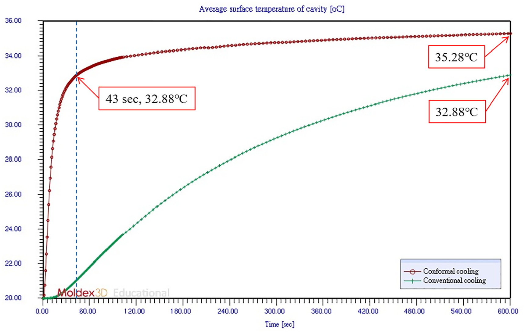
Average temperature of the mold cavity surface in the mold preheating stage for conformal (red) and conventional (green) cooling channels.
During mold opening and part ejection, the mold temperature was measured using an infrared thermography camera, and the results obtained were similar to the observations from the injection molding simulations. Figure 8 depicts the simulation results and actual thermal images for the core of the movable plate with the conventional cooling channels and conformal cooling channels, whereas Figure 9 presents the simulation results and actual thermal images for the cavity of the fixed plate. In actual measurements, the temperature difference for the core of the movable plate was 8.6°C and 8.3°C when the conventional and conformal cooling channels were used, respectively. The conformal cooling channels thus reduced this temperature difference by 0.3°C, a 3.49% improvement. The actual temperature difference for the cavity of the fixed plate was 9.7°C and 8.2°C when the conventional and conformal cooling channels were used, respectively. The conformal cooling channels thus reduced this temperature difference by 1.5°C, a 15.46% improvement. The aforementioned results indicate that the conformal cooling channel design, which followed the contour shape of the parts and enhanced cooling in the region where heat accumulated, reduced the mold temperature difference for the die core and cavity and improved the uniformity of the temperature within the mold. These factors helped optimize product quality.

(a, b) Simulation results and (c, d) actual thermal images for the core side when the (a, c) conventional cooling channels and (b, d) conformal cooling channels were used.
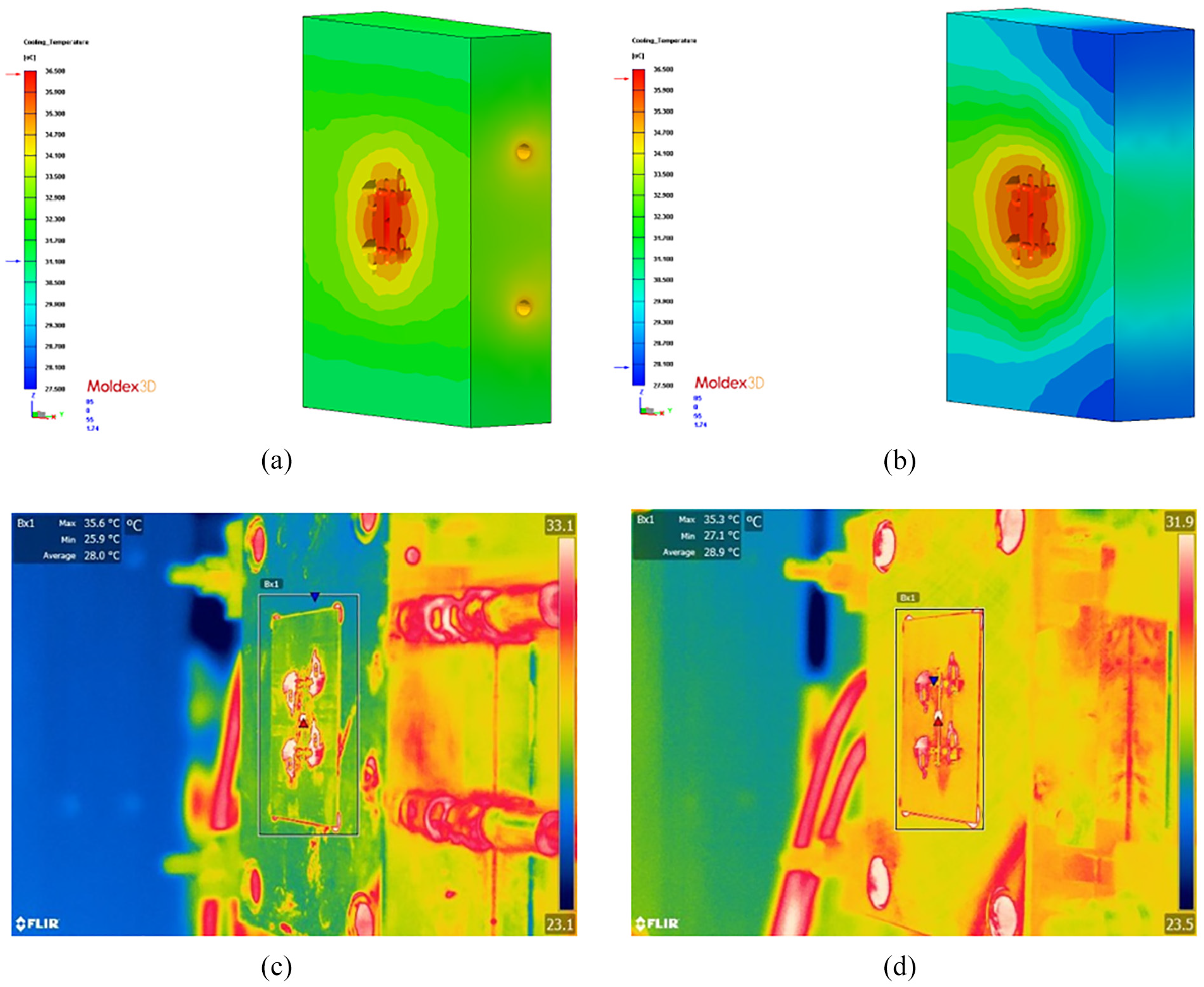
(a, b) Simulation results and (c, d) actual thermal images for the cavity side when the (a, c) conventional cooling channels and (b, d) conformal cooling channels were used.
Conformal cooling channels can increase the temperature uniformity of green parts. Because the green parts investigated in this study were thick, the central region of the parts cooled slower than the outer regions, indicating heat accumulation. The difference in the maximum temperature between the two types of cooling channels was only 0.593°C (Figure 10), indicating that the temperature in the central region of the part was not notably affected by the type of cooling channel. Because the mold temperature distribution for the conformal cooling channels was more uniform than that for the conventional cooling channels, the sink mark displacement was 2.38% lower for the conformal cooling channels (Figure 11).

Maximum temperature of green parts produced using conventional and conformal cooling channels.

Sink mark displacement of green parts produced using conventional and conformal cooling channels.
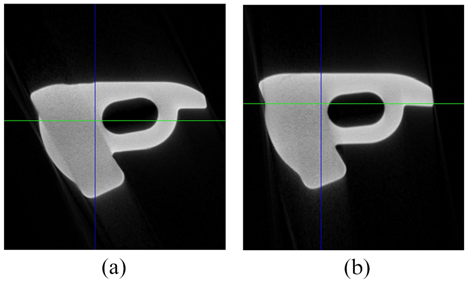
The dimensions of the green parts were measured. Because the die core and cavity with the conformal cooling channels had not been polished, the surface of the parts produced with these channels (Figure 12(b)) was rougher than that of the parts produced with the conventional cooling channels (Figure 12(a)). Surface finishing after de-binding, sintering, and heat treatment can reduce the surface roughness of sintered parts. CT was used to visualize the parts’ void defects and internal features (Figure 13). None of the green parts were found to have pores or holes, regardless of whether the cooling channels were conventional or conformal. In the future, posttreatments such as electroplating, carbon doping, and chemical grinding can be conducted for finished parts after sintering. The present study compared the three green parts created using the conventional and conformal cooling channels through three-dimensional measurements. The results presented in Table 1 indicate that the maximum difference was observed in the X-direction; using the conformal cooling channels led to a 0.11% smaller difference than did using the conventional cooling channels. No difference was identified in the Y-direction. Regarding the Z-direction, the conformal cooling channels led to a 0.04% larger difference than did the conventional cooling channels. The results revealed that when the cooling time used with the conformal cooling channels was shortened by 3 s, the dimensional accuracy of the green parts remained comparable to that achieved with the conventional cooling channels. The results also indicated that this shortening in the cooling time resulted in the dimensional difference in the X-direction being reduced by 0.11%. Therefore, using a conformal cooling channel mold can shorten the cycle time and improve the dimensional stability of green parts.
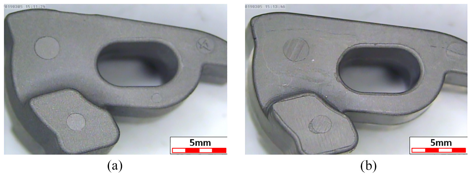
Surface roughness and shape of green parts obtained using (a) conventional cooling channels and (b) conformal cooling channels (observed under an optical microscope).
CT images of the internal morphology of green parts obtained using (a) conventional cooling channels and (b) conformal cooling channels.
Precision measurements of the dimensions of the fabricated green parts (unit: mm).

Conclusions
This study employed 3D printing of metal to manufacture die core and cavity prototypes with conformal cooling channels. The core and cavity were secondary-processed through CNC cutting, electric discharge machining, and grinding. However, secondary processes such as milling and polishing were not implemented to fine-tune the surface quality of the die core and cavity. Trial runs were conducted using die cores and cavities with conformal and conventional cooling channels, and the mold temperature was compared for these two types of cooling channels. Finally, the differences in the dimensions of green parts produced with the two types of cooling channels were determined. According to the simulation and experimental results, the conventional and conformal cooling channels had differing cooling efficiency. Because of the design limitations of conventional cooling channels, heat accumulated in the product and could not be easily discharged from the mold. Consequently, the cooling efficiency and mold temperature uniformity were not as high for the conventional cooling channels as for the conformal cooling channels. Mold temperature uniformity is crucial because it reduces the degree of uneven shrinkage of the part, thereby reducing warpage.
Compared with the conventional cooling channels, the conformal cooling channels increased the average temperature of the mold cavity surface during the mold preheating stage and shortened the time required for preheating. The conformal cooling channels effectively improved mold temperature uniformity because they were closer to the surface of the part; thus, they could effectively reduce the heat generated during molding. The maximum temperature of the green parts under the conformal cooling configuration was 0.5% lower than that under the conventional cooling configuration. The conformal cooling channels resulted in more uniform volume shrinkage of the green parts, reducing the surface sink mark displacement and warpage displacement. According to the literature, 19 the degree to which green parts deform is proportional to the warping deformation of final sintered parts. In the present experiment, the dimensional accuracy of the green parts obtained using the conformal cooling channels was comparable to that obtained using the conventional cooling channels. In addition, the cycle time was successfully shortened using the conformal cooling channels.
This study did not investigate the effects of process parameters on the mechanical properties of a mold fabricated through laser AM. However, the laser spot size is a crucial process parameter and strongly influences the microstructure, roughness, hardness, density, and residual stress of AM-built specimens. As the laser spot size increases, the residual stress decreases. 20 The scanning strategy also affects the residual stress, which causes deformation and crack initiation in the builds. 21 Therefore, a possible future research direction is to optimize the process parameters and scanning strategy for laser AM. Such optimization would require a numerical model 22 to identify suitable scanning strategies for reducing residual stress and deformation in an AM-fabricated mold. Overall, the results of this study indicate that integrating injection molding simulation with MAM to fabricate conformal cooling channels inside MIM molds is feasible in industrial applications.
Supplemental Material
sj-docx-1-ade-10.1177_16878132241282210 – Supplemental material for Metal additive manufacturing of conformal cooling channels for improving the quality of metal injection–molded products
Supplemental material, sj-docx-1-ade-10.1177_16878132241282210 for Metal additive manufacturing of conformal cooling channels for improving the quality of metal injection–molded products by Chen-Yuan Chung and Chuan-Jen Liu in Advances in Mechanical Engineering
Footnotes
Handling Editor: Sharmili Pandian
Declaration of conflicting interests
The author(s) declared no potential conflicts of interest with respect to the research, authorship, and/or publication of this article.
Funding
The author(s) disclosed receipt of the following financial support for the research, authorship, and/or publication of this article: This research was partially supported by grant NSTC 112-2622-E-008-016 from the National Science and Technology Council in Taiwan. This work was also supported by LioHo Machine Works, Ltd. The injection molding simulation software Moldex3D was run under academic license with the serial number 29769.
Supplemental material
Supplemental material for this article is available online.
References
Supplementary Material
Please find the following supplemental material available below.
For Open Access articles published under a Creative Commons License, all supplemental material carries the same license as the article it is associated with.
For non-Open Access articles published, all supplemental material carries a non-exclusive license, and permission requests for re-use of supplemental material or any part of supplemental material shall be sent directly to the copyright owner as specified in the copyright notice associated with the article.