
Abstract
This study focuses on novel design and evaluation of Elastic 50A (EL50) mechanical metamaterials with open-cell patterns for its potential application to lower limb residuum/socket interfaces, specifically that of a transtibial (TT) amputee. Mechanical characteristics, that is, effective Young’s modulus (E), was tuned by altering metamaterial porosity, which was experimentally verified. Specifically, pore radius of the unit cell was varied to achieve a range of E-values (0.05–1.71 MPa) for these 3D printed metamaterials. Finite Element Analysis (FEA) was conducted to evaluate pressure distribution across key load-bearing anatomical sites of a TT residuum. Using designed metamaterials for homogeneous liners, pressure profiles were studied and compared with a silicone liner case. Additionally, a custom metamaterial liner was designed by assigning appropriate metamaterials to four load-sensitive and tolerant anatomical sites of the TT residuum. The results suggest that lowest pressure variation (PV), as a measure of pressure distribution levels and potential comfort for amputees, was achieved by the custom metamaterial liner compared to any of the homogeneous liners included in this study. It is envisaged that this work may aid future design and development of custom liners using now commonly available 3D printing technologies and available elastomer materials to maximise comfort, tissue safety and overall rehabilitation outcomes for lower limb amputees.
Keywords
Introduction
The interface between the lower limb residuum and the prosthetic socket is critical to facilitate effective load transfer and ensure user stability and comfort during activities of daily living. 1 Residuum tissues are not biologically accustomed to endure prolonged exposure to multidirectional forces. The presence of scar tissue can further compromise its tolerance to external loading. Prosthetic liners, typically made of silicone or polyethylene foam, are often worn by amputees to provide cushioning and protection to residua tissue from the hard socket wall. 1
Mechanically compliant liners help distribute load across the residuum/socket interface. Even pressure distribution is known to be desirable for socket comfort and thus overall rehabilitation outcomes. 2 Even pressure distribution is also the underlying principle for hydrostatic sockets2,3 which have been widely used for transtibial (TT) amputees. However, achieving relatively even load distribution through liner designs has proved challenging, particularly for TT amputees due to the existence of bony prominences (e.g., tibial end, fibula head and tibial tuberosities). 4 Consequently, interface stresses can vary significantly across different TT residuum anatomical sites. 5 For instance, Sanders et al. 4 reported interface pressure of up to 224 kPa at anterior-distal sites (contains a bony prominence) compared to 115 kPa at the popliteal fossa (PF) site (no bony prominence). Laing et al. 6 also reported pressure of up to 173 kPa at anterior-distal and 86 kPa at PF sites. The uneven distribution of these stresses, especially elevated loading at load-sensitive bony prominence sites, is known to affect comfort and may increase the risk of tissue injury (e.g., ulceration).3,7,8
Although prosthetic sockets are usually bespokely made to accommodate user-specific characteristics (e.g., residuum shape, tissue mechanical properties, painful sites), 9 most conventional prosthetic liners are batch-produced. In order to help distribute interface load, thus improve comfort and overall rehabilitation outcomes, custom liners have been reported, 9 though most of them focus on adapting to the shape of the residuum while still using conventional silicone materials. 10 Many studies have been conducted to understand the effect of liner material and geometry on interface load distribution with a view to improve load distribution.11,12 A recent review 9 suggests that changing localised liner material stiffness has proved effective in helping load redistribution. However, current manual approaches to achieve this, for example, cutting out ready-made silicone liners at load-sensitive sites then replacing them with silicone of different thickness,9,10 is an inefficient means of producing patient-specific liners. The sole use of conventional silicone materials also limits material choices, design freedom and manufacturability to achieve an even load distribution for personalised liners.
3D printing has been exploited as a promising means of producing prosthetic sockets 13 and moulds 14 for custom silicone liners, as it can accommodate complex residuum shapes in design and manufacturing to an appropriate level of accuracy. 15 Advancements in additive manufacturing technology means that a more comprehensive range of elastomeric materials exhibiting a wider range of stiffness, as compared with that of silicone, can now be exploited. On the other hand, the inception of elastomeric mechanical metamaterials has attracted significant interest in recent years, as their mechanical properties (e.g., geometry and stiffness) can be tuned by altering the architecture of unit cells and structures while still maintaining usage of the same base material.15,16 3D printed elastomers 17 in particular show great promise for a range of biomedical applications due to high flexibility, strength and variable stiffness for applications involving complex surface contours such as TT residua in this study. Indeed, Brown et al. 18 reported an initial study involving the use of 3D printed TangoPlus 19 metamaterials as interface materials to offload pressure at the residuum/socket interface. However, there lacks systematic studies on the design and evaluation of prosthetic liners, especially custom liners.
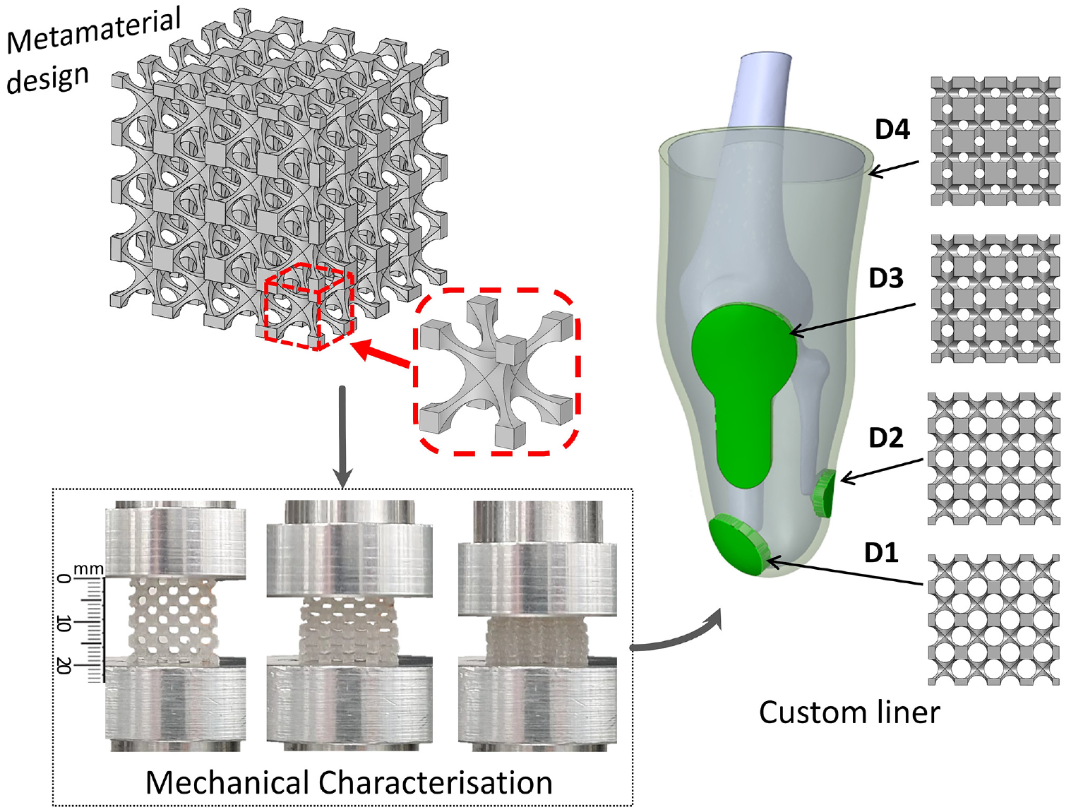
This paper reports a preliminary study focusing on design and development of mechanical metamaterials based on Elastic 50A® (EL50) 20 elastomeric material, which is widely accessible for table-top 3D printers. The specific aim is to improve the distribution of pressure across anatomical sites of a TT residuum. Metamaterials made of elastomeric material were designed based on an open unit cell with varying porosity in order to achieve different stiffnesses. The mechanical properties of the metamaterials were experimentally evaluated. Finite Element Analysis (FEA) was used to assess pressure distribution across the TT socket interface for homogeneous liners. A novel custom liner was subsequently designed to comprise different metamaterials across residuum anatomical sites with a view to improve pressure distribution. It is envisaged that this may help shed light on the means and potential of exploiting table-top 3D printers and associated elastomeric metamaterials for future development of personalised prosthetic liners.
Materials and methods
Design and fabrication of metamaterials
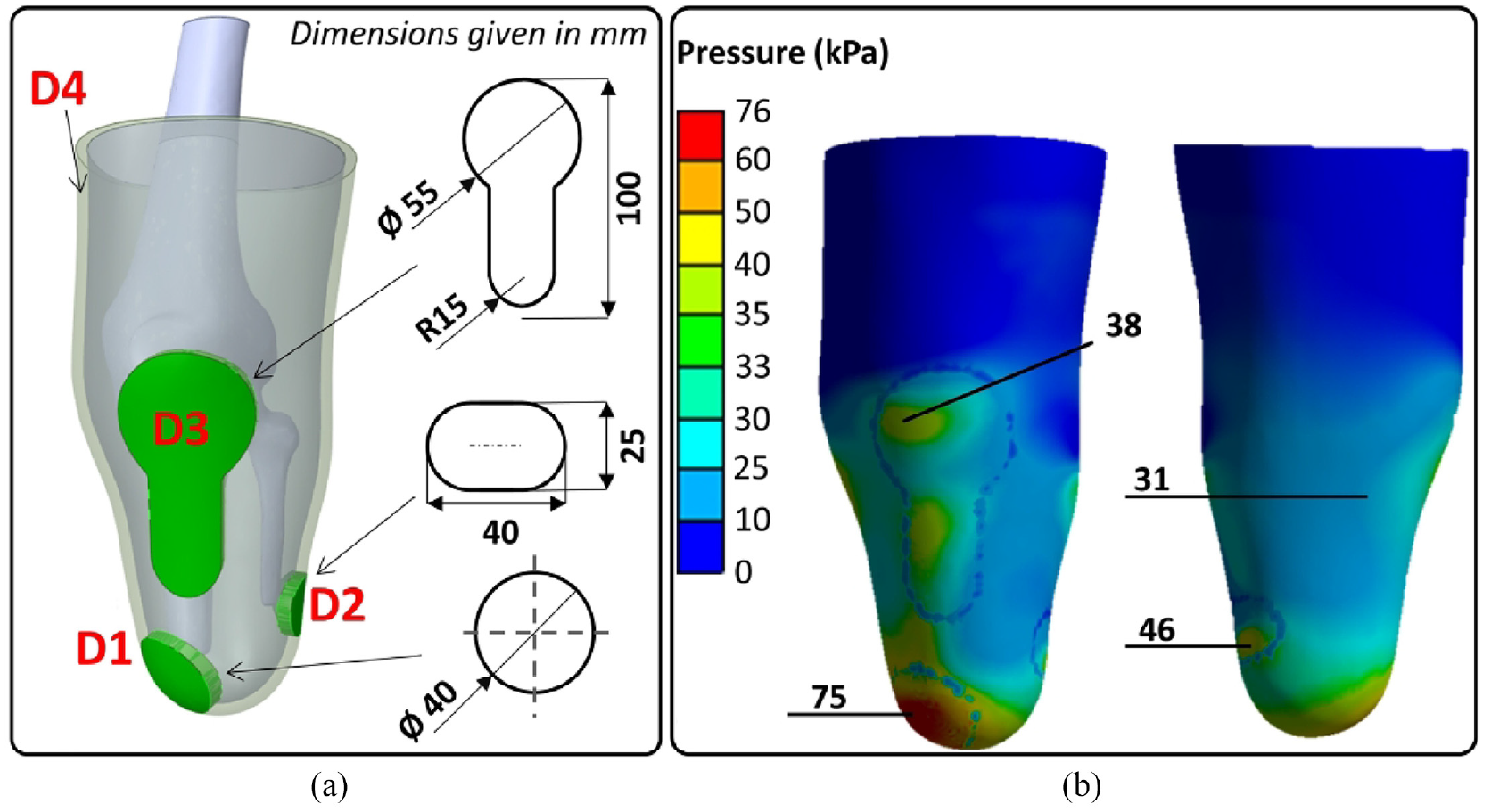
A simplified 3D cellular unit was chosen for the metamaterial design, as shown in Figure 1(a). Such cellular unit is well-known for achieving a wide range of effective Young’s modulus (E) (1–1000 kPa) 21 and therefore have been used for body support applications.7,22,23 The 3D cellular unit is defined by two critical design parameters, that is, the cell size (u) and pore radius (r), as illustrated by the cross-sectional view (Figure 1(b)). Both u and r affect the relative density (ρr) and porosity (φ) of the 3D cellular unit, 24 thus affecting E. In this study, a typical cell size u = 5 mm was chosen. This falls in the range of typical liner thickness of approximately 3–10 mm11,25 while liners of progressive thickness can also reach up to 16 mm distally. 26 Furthermore, it is not uncommon to use cellular materials consisting of a singular or few cell layers. 27 The 3D cellular units were stacked in all directions to produce isotropic metamaterial samples with a dimension of 20 × 20 × 20 mm (Figure 1(c) and (d)). The sample dimensions were chosen based on the consideration of BSI Standards for compression tests of rubber-like materials, 28 whereby an aspect ratio of greater than or equal to one is recommended. Such sample dimensions are also sufficiently larger than the unit cell size (u = 5 mm), which was recommended 27 for experimental evaluation of E for open-cell foams.
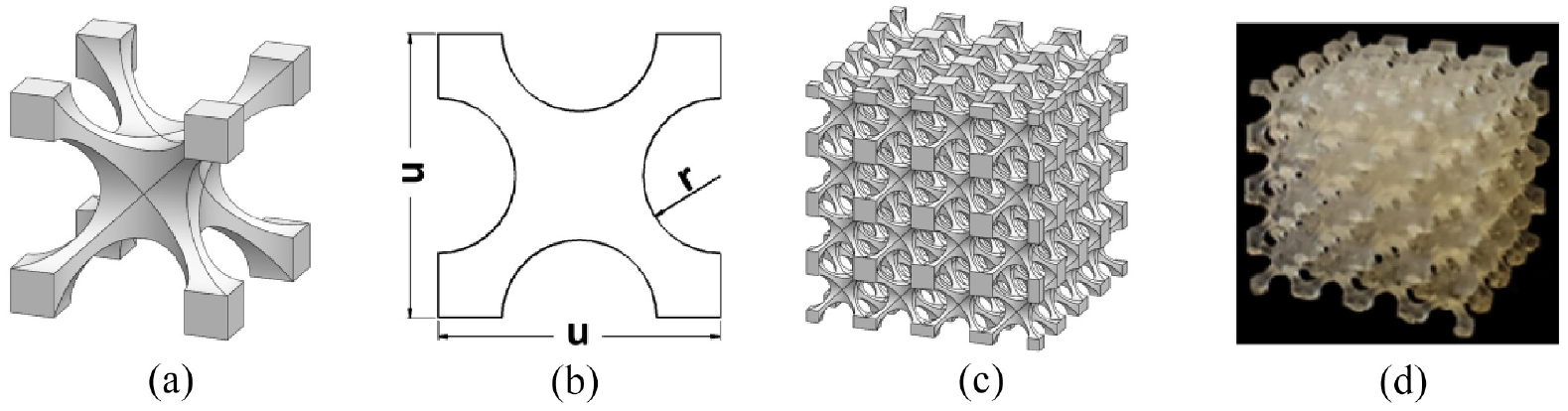
Schematics showing (a) a design of a typical 3D cellular unit, (b) cross-sectional view of the 3D cellular unit and (c) a metamaterial formed by stacking 3D cellular units. (d) A printed metamaterial.
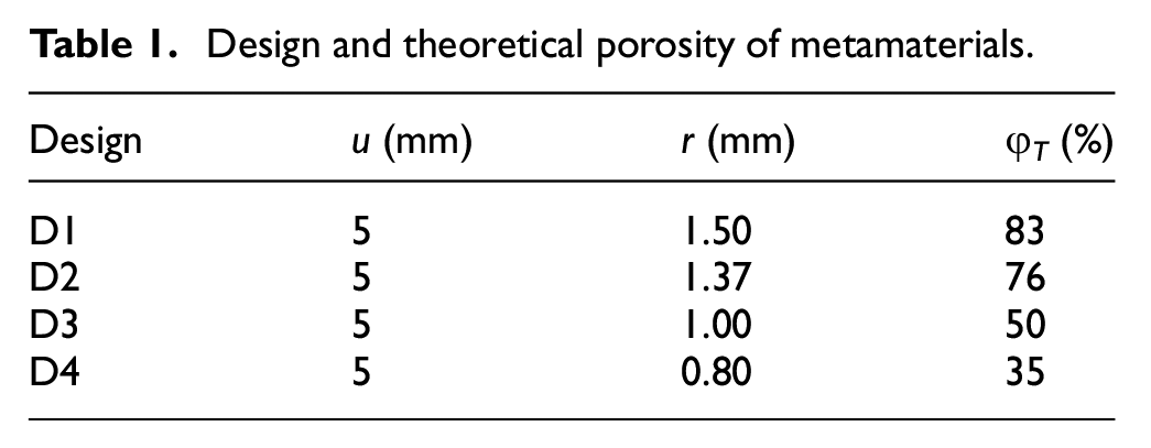
The theoretical porosity (φT) of the metamaterials was evaluated based on equation (1), using SolidWorks 2022 (Dassault Systèmes, France), where Vp represents the volume of pores and Vs is the solid volume.
Table 1 shows that φT changes with the variation of r, while u was held constant at 5 mm. The range of r was selected in such way in order to obtain the appropriate range of metamaterial porosity in this study.
Design and theoretical porosity of metamaterials.
The designed metamaterials along with solid EL50 samples were 3D printed using a stereolithography Form 3 printer (Formlabs Inc., Germany), as shown in Figure 2. The 3D printed samples were then washed using isopropyl alcohol for 20 min and subsequently cured for 20 min at 60°C, as recommended by the manufacturer.
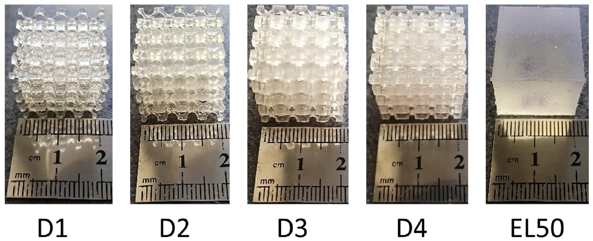
Fabricated samples.
Characterisation of metamaterials
Densities of metamaterials (ρm) and solid EL50 (ρEL50) were obtained from measured volume and mass of the samples. Relative density (ρr) is subsequently defined in equation (2), 29 which is known for cellular structures. φe represents experimentally induced porosity.
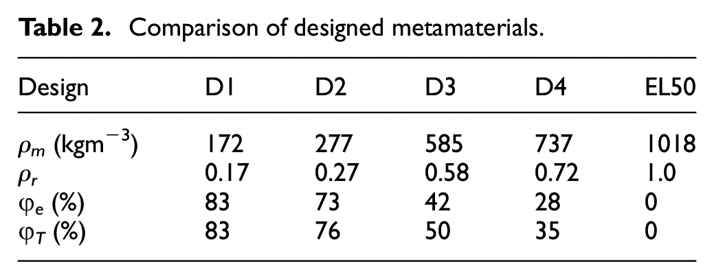
Table 2 shows measured ρm and corresponding ρr and φe which were calculated based on equation (2). The theoretical porosity, that is, φT (equation (1)) is also included and show good alignment with φe. The minor discrepancies may be caused by slight variations in manufacturing (e.g., pore radius slightly differing from theoretical designs).
Comparison of designed metamaterials.
Mechanical compressive loading tests were performed on the samples using a uniaxial material test machine (ElectroPuls E1000, Instron, Illinois Tool Works Inc., US) and a typical test setup is shown in Figure 3. Compressive load of up to 80 N was applied to each sample while corresponding strain was measured simultaneously. This is equivalent to a peak pressure of 200 kPa, which has been commonly reported 4 at TT residuum/socket interfaces. At least four repeated tests were conducted for each sample and the mean of stress-strain curves were produced. E-values were obtained through linear fittings of the stress-strain curves.
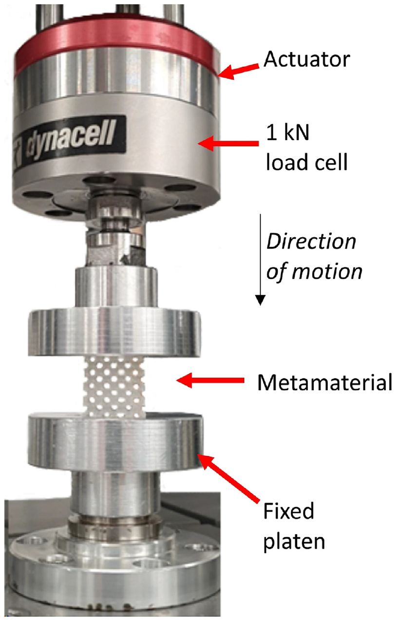
A typical compressive loading test setup.
FEA of the TT residuum/socket interface
FEA was conducted using ANSYS 2021R2 (ANSYS Inc., US) to assess pressure distribution across a residuum/socket interface when liner materials with varied E were assigned. Models were constructed using MeshMixer 3.5 (Autodesk Inc., US) and SolidWorks. A 3D TT residuum model was established by scanning a positive cast of a TT residuum. A truncated TT bone module model was created in accordance with surgical guidelines of TT amputations and a detailed description was reported previously by McGrath et al. 30 Subsequently, a bone cavity was created within the residuum to host the truncated bone model. The solid liner was constructed by extruding the exterior surface of the residuum 18 uniformly by 5 mm in the direction normal to the residuum. This thickness is equivalent to a single layer of the unit cell (u = 5 mm) as shown in Figure 1(a). The socket was constructed likewise, except the exterior liner surface was used as the extrusion reference. This ensured liner/residuum and liner/socket interfaces were flush against each other to emulate in-vivo socket interface interactions. 18 The complete 3D model for FEA is shown in Figure 4.
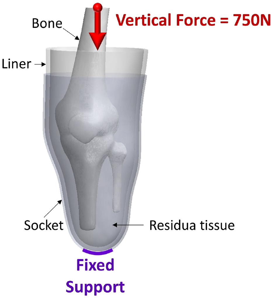
Boundary conditions applied to interface components.
A fixed support was applied to the socket’s distal-end while a vertical load of 750 N was exerted on the bone. This equates to a peak vertical ground reaction force during ambulation from an amputee with an average bodyweight of approximately 70 kg. It was reported 31 that the peak vertical ground reaction force is approximately 110% of that of bodyweight. Bone/residuum and residuum/liner interfaces were assumed bonded and a coefficient of friction of 0.5 was applied to the liner/socket interface to represent a sticky surface between liner and residuum and greater sliding between liner and socket, which are commonly used to simulate elastomeric liners. 31 Table 3 lists material properties,31–33 that is, E and Poisson’s ratio (ν), used in FEA including those for a typical silicone liner. 11
Material properties used in FEA.
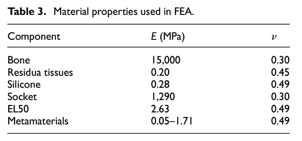
The range of E-values of metamaterials were assigned to the solid liner layer of 5 mm thickness based on experimental data obtained from compressive loading tests on 20 × 20 × 20 mm samples (Figure 2). It is important to note that the stiffness of a single layer of unit cells may vary slightly compared with respective bulk test samples based on a study of the mechanical behaviour of foams with random (Voronoi) pore size and morphology. 27 However, while the distribution of pore size and morphology play a key role in size effects on stiffnesses for Voronoi microstructures, for the unit cell designs adopted in this work (as shown in Table 2), the distribution of pore size and morphology are nominally the same in both single cell and test sample cases. It is thus plausible to assume that there is little size effect on stiffness in this work. Therefore, E obtained from corresponding compression experiments were used as liner stiffnesses in FEA. This also ensures the primary focus to be on the relative comparison across different metamaterial designs, that is, D1–D4. ν of 0.49 was used for metamaterials in this study since isotropic open-cell structures were reported to exhibit ν of close to 0.5 at low densities.29,34 Therefore, ν of 0.49 were assigned for all liner materials in this study as they are all highly elastic materials.
FEA was conducted considering homogenous liner cases first, whereby corresponding E-values of metamaterials, silicone and EL50 were assigned to the entire liner region, respectively. Pressure distribution across anatomical sites of the TT residuum were studied. Based on these comprehensive studies, a novel custom liner was subsequently designed comprising metamaterials with differing E-values at four different anatomical sites of the TT residuum. Specifically, different metamaterials were assigned to four identified liner regions corresponding to the distal tibial-end (DTE), distal fibula-end (DFE), patella tendon (PT) and popliteal fossa (PF) sites, which are known load bearing and sensitive sites for TT residua.32,35 The shapes and geometry of the respective liner regions were chosen based on commercially-available pressure pads 36 that are commonly used in clinics to help improve socket comfort for TT amputees.2,36,37 Pad locations were centred around the pressure concentration point, that is, the highest pressure location in each specific region. Within each liner region, the E-value was kept the same as that of the assigned metamaterial.
Pressure variation (PV) was introduced as a measure of pressure distribution whereby lower PV corresponds to a more evenly distributed profile, as shown in equation (3), where
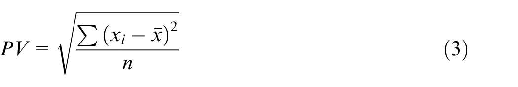
In this work, peak pressure at four anatomical sites, that is, DTE, DFE, PT and PF, were extracted from FEA results in order to obtain PV, thus n = 4 was used. Peak pressure was obtained at the same sites for all FEA studies, ensuring validity of PV comparisons.
Results and discussion
Mechanical characterisation of metamaterials
Figure 5(a) shows stress-strain curves obtained from compressive loading tests including the corresponding linear fittings. Figure 5(b) shows that E increases as ρr increases. Curve fitting indicates a power-law relationship between E and ρr (R2 > 0.973), as shown in equation (4), where n is a constant dependent on the structure.24,29

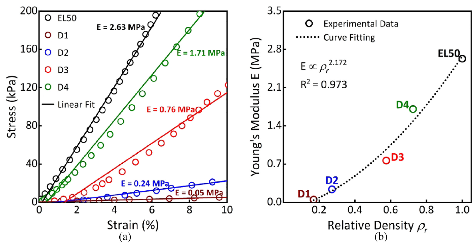
(a) Compressive stress-strain curves. (b) E of different metamaterial designs as a function of ρ r with power-law fitting.
Exponent (n) of close to 2 (n = 2.17) in Figure 5(b) aligns well with those typically observed for open-cell foams, 34 exhibiting bending-dominated deformation mode for these metamaterials. This indicates a significant decrease in E as ρr decreases.24,29 This experimentally validates our metamaterial design and the corresponding E-values that were subsequently used as inputs for FEA in this study. It is also important to note metamaterials were designed such that their E-values are in the approximate range of 0.05–1.71 MPa (Figure 5(a)), which roughly covers the wide range of reported tissue properties (0.05-2 MPa).31,38
Pressure distribution from FEA
Figure 6 shows pressure distribution across the residuum when using homogeneous liners made of different materials, obtained via FEA. For all cases, pressure values were relatively higher at DTE and DFE as compared with those at PT and PF. This is primarily due to the existence of the tibial tuberosity at DTE and truncated fibula bone at DFE, whereby bony prominences are responsible for elevated pressure. 4 In particular, peak pressure at DTE (100–135 kPa) and DFE (55–61 kPa) range across different homogenous liners, which fall in the range of typical values reported at TT residuum/socket interfaces (up to approximately 200 kPa).4,6,8 High DTE pressure was previously linked to pain and increased risk of mechanically-induced tissue breakdown 39 as it is clinically poor at sustaining load. 31 Likewise, the DFE also exhibits a stress “hotspot” due to load transmission down through the fibula shaft towards the truncated fibula, resulting in accumulative pressure. Although comparatively lower than that at DTE, it is equally important to prevent stress accumulating at this site as it too cannot tolerate high loading. 32 In contrast, peak pressure ranges were comparatively lower at PT (37–43 kPa) and PF (30–35 kPa) sites when different homogenous liners were adopted in FEA. PT and PF are known key load-bearing sites whereby pressure of up to approximately 100 kPa 8 and 115 kPa 4 have been reported, respectively. The PF is also known for its ability to redistribute pressure due to the existence of the gastrocnemius muscle (i.e., large tissue presence), 37 which explains why obtained pressure was the lowest of the four sites.
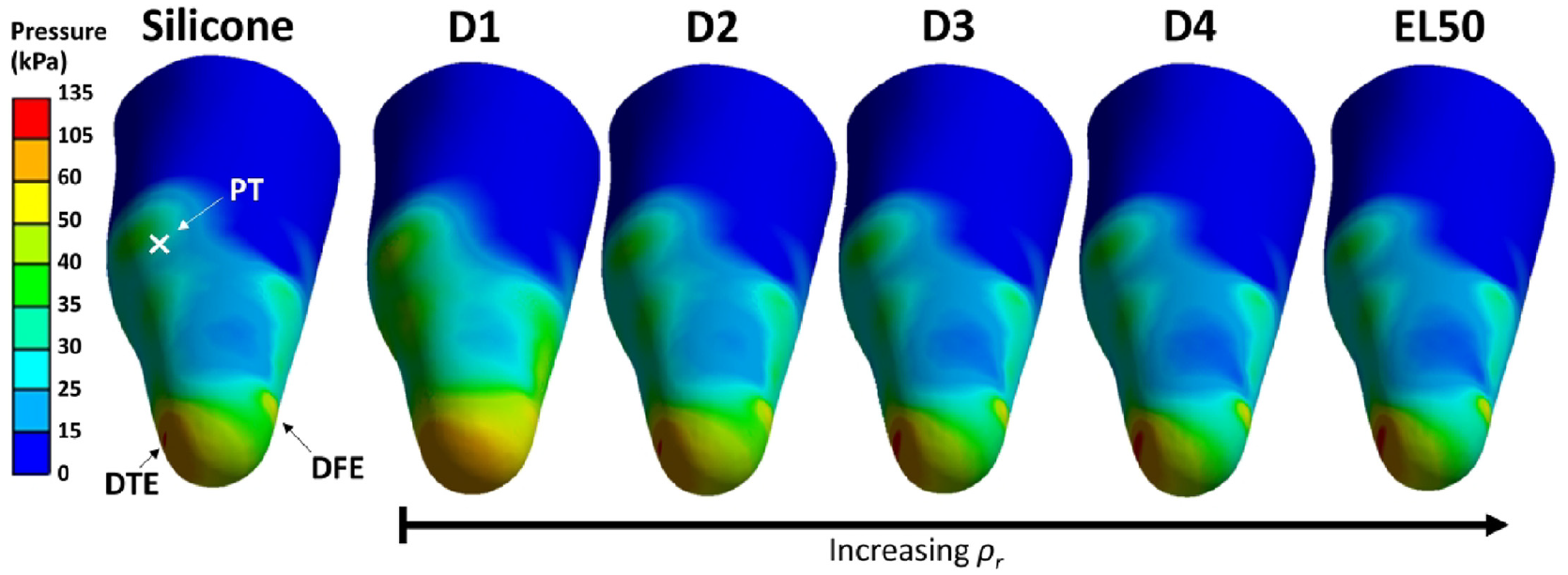
Pressure distribution with homogeneous liners made of silicone, D1, D2, D3, D4 and EL50.
Figure 7 compares peak pressures obtained from FEA using different liner materials. D1 resulted in lowest peak pressure at DTE (100 kPa) but highest at the DFE site (61 kPa). Lower pressure at DTE is expected for D1 liner due to its low stiffness (E = 0.05 MPa), that is, the most compliant material as compared with all other counterparts. The pressure increase observed at DFE, PT and PF further indicates the shift of loading profiles and thus demonstrates the importance of considering pressure distribution across residuum loading sites as a whole.
Peak pressure obtained at the DTE, DFE, PT and PF of the residuum as a function of liner materials.
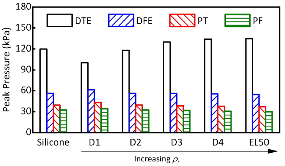
A novel custom liner was thus designed in order to achieve pressure distribution, that is, lowest PV across DTE, DFE, PT and PF sites. Different metamaterials were assigned to four identified liner regions as shown in Figure 8(a). Previous findings suggest9,11 that an ideal liner should possess higher E at sites with greater tissue presence to limit relative motion, and lower E at sites of high stress concentration to alleviate pressure. We thus assigned D1, D2, D3 and D4 to DTE, DFE, PT and PF sites, respectively. In essence, metamaterials with lower E were assigned to anatomical sites associated with relatively higher pressure, with a view of achieving lower PV, that is, improved pressure distribution. In particular, D1 (lowest E of 0.05 MPa) was assigned to DTE (highest pressure concentration site), while D4 (highest E of 1.71 MPa) was assigned to the remaining residuum region, as shown in Figure 8(a), which encompasses the PF (lowest pressure site). Figure 8(b) shows the pressure distribution resulting from FEA for the custom-designed metamaterial liner.
(a) A custom liner with metamaterials applied at the four sites. (b) Pressure distribution across the residuum.
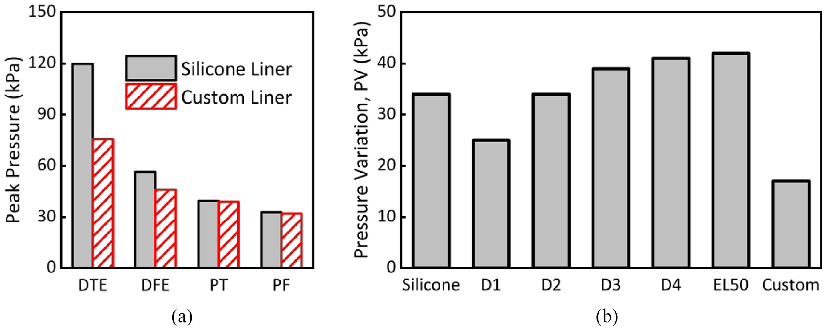
Figure 8(b) shows that peak pressures at DTE (75 kPa), DFE (46 kPa), PT (38 kPa) and PF (up to 31 kPa) were obtained for the custom liner case. In comparison to homogeneous liner cases (Figure 6), pressure decreased substantially at DTE and DFE bony prominence sites, while pressure remained similar at PT and PF load-bearing sites. Figure 9(a) specifically compares FEA peak pressure values between the custom metamaterial liner and its typical silicone counterparts. The custom liner resulted in a reduction in pressure at DTE (75 kPa vs 120 kPa) and DFE (46 kPa vs 56 kPa), with no notable change at PT and PF. Figure 9(b) shows PV for the custom liner compared to that of silicone and other homogenous liner cases. It is important to note that the custom liner revealed the lowest PV (approximately 17 kPa) compared to any other homogeneous liner (Figure 9(b)). In particular, PV is even lower than that of the “softest” liner (D1, E = 0.05 MPa), further demonstrating the need for customised liners. Thus, a custom metamaterial liner could be designed and printed to achieve a more even pressure distribution across the residuum in order to improve socket comfort and tissue safety. 3 This allows effective pressure offloading from load-sensitive (e.g., DTE and DFE) to load-tolerant sites (e.g., PF).
(a) Peak pressure obtained at the four sites for the silicone liner versus the custom liner and (b) PV for the homogeneous liners compared to the custom liner.
Based on this preliminary research, optimisation of metamaterial designs and properties could be conducted to further reduce PV and potentially accommodate a wider range of bespoke residua profiles and tissue properties. This could be potentially achieved at the personalised liner design stage, whereby metamaterials with a wide range of stiffnesses could be achieved by further varying key unit cell design parameters such as pore radius and unit cell size. As such, metamaterials of different stiffness could be allocated at different anatomical regions based on bespoke loading profiles and tissue properties of each individual residuum to form a custom liner. It is envisaged that the entire liner could then be 3D printed to comprise purposely-designed liner sections with varied stiffnesses to minimise overall PV. Moreover, while only vertical load was applied in FEA in this preliminary research, in future work, it would be beneficial to apply multidirectional forces mimicking different loading phases of a gait cycle. This would allow comprehensive assessment of pressure distribution during walking. Further reduction of PV could also be conducted explored by using other 3D printing elastomers or choosing different unit cell designs. Future work is also required to conduct real-world amputee tests, whereby real-time pressure measurements at residuum/socket interfaces and level of comfort can be studied and compared when using custom liners and other homogenous liners, such as habitual silicone liners.
Conclusions
This preliminary study involves design and evaluation of 3D printed mechanical metamaterials based on EL50 elastomer, and their potential applications as liner materials for TT residuum/socket interfaces. Open-cell unit metamaterials were designed with varying porosity to achieve a range of stiffness, that is, E in the range of 0.05–1.71 MPa, which were verified by experimental compressive loading tests. A power-law relationship between ρr and E was identified that aligns well with the predicted relationship for open-cell structures. In the case of homogenous liners, FEA results show pressure was comparably higher at DTE (up to 135 kPa) and DFE (up to 61 kPa) sites than that at the PT (up to 43 kPa) and PF (up to 35 kPa) in all cases. Use of the most compliant material, that is, D1 (E = 0.05 MPa) led to notable pressure reduction at DTE. Furthermore, a novel custom metamaterial liner was designed with selective designation of metamaterials to different anatomical sites. FEA results show that lowest PV can be achieved by the custom liner as compared to use of homogeneous silicone and metamaterial liners. This potentially offers a promising means to design and develop a range of 3D printed custom liners with improved comfort and tissue safety for individual amputees.
Footnotes
Acknowledgements
The authors acknowledge the use of the IRIDIS High Performance Computing Facility, and associated support services at the University of Southampton, in the completion of this work.
Declaration of conflicting interests
The author(s) declared no potential conflicts of interest with respect to the research, authorship, and/or publication of this article.
Funding
The author(s) disclosed receipt of the following financial support for the research, authorship, and/or publication of this article: Kirstie M. Devin acknowledges the support of the UK Engineering and Physical Sciences Research Council (EPSRC) grant EP/S02249X/1 for the Centre for Doctoral Training in Prosthetics and Orthotics to provide PhD studentship.