
Abstract
The existing crisis has accentuated problems related to the energetic perspective which forces the industrial framework to take actions. Natural stone companies are those more deteriorated by the crisis since they depend on the construction sector. While it is true that embedded energy in the natural stone industry includes extraction, transport and processing stages, the abrasive effect of sawing and polishing activities is responsible for the most energy consumption in stone manufacture. For this reason, improving sawing processes could have a major impact on the natural stone sector. This article presents a design of a new thinner diamond segmented circular sawblade for marble sawing, which reduces energy consumption during the sawing process. First of all, a multi-axis force measurement system was employed to determine the cutting conditions of a conventional diamond segmented circular sawblade under a pre-set configuration. Then, the research team defined a digital prototype of a commercial diamond segmented circular sawblade, and the data extracted from experimental measurements were used to configure the simulation. The simulation provided information about the mechanical performance experienced by the circular sawblade (such as stresses, displacements and eigenfrequencies). Subsequently, the geometry of that commercial circular sawblade was optimised seeking to reduce the moment of inertia while keeping the mechanical performance within safe and functional limits. At the end of the research, it was experimentally demonstrated that the new thinner circular sawblade designed reduces energy consumption during a sawing operation compared to the commercial circular sawblade.
Keywords
Introduction
Natural stone can be used in numerous applications related to construction due to its beauty and mechanical–thermal behaviour. Although the natural stone sector has seen its profits fall since it ranks as one of the sectors that have been hit the hardest by the financial crisis. However, this negative effect has made no impact on the energy bill and energy consumption and instead costs kept on growing. Nowadays, energy supply remains an important challenge and that is the reason why this sector needs a significant amount of resources focused on increase productivity and lowering energy utilisation.
Background of the study and statement of the problem
Those companies related to the natural stone sector are widely influenced by the financial crisis. The research centre Aidico, the association Ami and the firm Levantina worked collaboratively. As a result of this collaboration they completed an energy diagnosis and, thus, they had an understanding of the situation. This research has allowed knowing the current energy situation and let recognise significant spots and recommend improvements.
The results of the research presented by González-Penella et al. 1 highlighted the significance of electricity compared to gas, which represents 70%-90% of the total energy consumption (see Figure 1). This research also confirmed that sawing has the highest impact on the electric bill, reaching values higher than 50% of total electrical energy consumption (see Figure 1).

Energy consumption in a representative slab and tile production line in a natural stone company.
After fulfilling the energy analysis, the research group proposed several lines of action to add innovations in locations of the production process where the energy consumption is important. One of them is focused on improving energy efficiency related to cutting tools. This article presents the results of that research line which has led to redesign the geometry of diamond segmented circular sawblades.
Review of related literature
Literature about technological enhancements
Within the last century, stone sawing technologies have changed substantially. In that sense, Carosio and Paspaliaris 2 found that introducing synthetic diamonds provide faster and profitable sawing processes as well as making use of numerical control systems allows precise sawing of stone with almost no restrictions. Along with the above-mentioned, several developments aimed to raise the efficiency of stone machining were released over the past few years. In spite of all these technological enhancements, the main problems associated with the current natural stone production chain include very low efficiency, the huge total waste originated and significant fluctuations in quality and performance during application of the final products.
Literature about diamond segments impact
There are several studies focused on the diamond segmented circular sawblades for natural stone sawing processes. The study of Konstanty 3 described the sawing mechanism and structural properties of those tools and assessed the factors that are supposed to influence the sawing process. Based on this study, other authors studied the selection and utilisation of the diamond segmented circular sawblades. In that sense, some aspects that affect how sawblades work are workpiece properties, functioning conditions, refrigeration, maintenance of the machine, metal core design and so on. While Luo and Liao 4 investigated how the geometry and morphology of the diamond impact on it, Luo 5 researched about behaviour of worn surfaces of the diamond segments in a circular saw; indeed, worn particles taking place at the segment surface make a sawing operation less efficient. Buyuksagis 6 also found a relation between the wear level and the power consumption. Another important finding in this field was presented in the work of Kitkiewicz and Świerzy. 7 Their research resulted in a formulation which relates the influence of the amount of tin in the metal matrix composition of a sintered circular sawblade. This content helps to increase hardness but the relation differs a lot for a difference of 1% in the amount of the matrix composition percentage.
Literature about wearing analysis
Polini and Turchetta 8 decided to investigate deeper in the field related to monitoring of the cutting operation. They developed and experimented with a new sensor system that permitted to study cutting forces and accelerations along the spindle axis. As a result, they concluded that the analysis performed using these kinds of systems leads to accurate conclusions about the wearing performance of the circular sawblade. Other investigation carried out by Yılmaz et al. 9 was centred on the influence that has rock properties on the wear performance. This work indicates that the properties of a rock are not related to the wear of the sawblade segment. 9 Yılmaz 10 also researched about how the rock hardness indexes can affect the abrasive wear. Yılmaz concluded that Vickers and Rosiwal hardness can be used to define the abrasivity of granite.
Literature about the influence of cutting conditions
With regard to the force values involved in a sawing operation, Xu et al. 11 performed an experimental investigation by which researchers studied the characteristics of the cutting forces in a circular sawblade tested on several kinds of granite over a very wide range of cutting conditions. Additionally, Ersoy and Atici 12 tested several rocks that were sliced using three sorts of circular sawblades; the performance of the sawing process depends on the cutting conditions and rock properties. The understanding resulted from those works is important for the design of an optimised sawblade and an appropriate setting of cutting conditions. Yılmaz and Göktan 13 studied the impact that the sawing rate has on both force and energy specifications. Researchers found out that applying higher feed rates (and also cutting rates) leads to a higher efficiency magnitude of the cutting process. Then Turchetta 14 also analysed how cutting forces and power consumption are affected by other variables related to the cutting process. In fact, Turchetta established an empirical model which allows to anticipate these parameters as a function of depth of cut and feed rate. He also defined a formulation that defines how cutting forces are tied to thickness of the chip removed by a single diamond (which is directly related to the width of the teeth).
Literature about feasibility of simulation
Another important phase of this research relates to the simulation study of the sawblade. In that sense, Yaşitli et al. 15 demonstrated that finite element analysis (FEA) could effectively be used for simulating a natural stone sawing process; Yaşitli et al. 15 developed a discrete element model and it was supplemented with various models that evaluated diverse feed rates and spindle speeds while real sawing set-ups were executed simultaneously. At the end, Yaşitli found simulation results to be quite compatible with real tests.
As it can be seen, during the last years, there have been a several works related to analysis of the cutting process (analysing cutting forces, energy consumption, input parameters, etc.), study of the behaviour of the sawblade and also about the characteristics of the diamond segments. However, only a few researches have been focused on the geometrical properties of the circular sawblade. For example, Yılmaz 16 dealt with vibrations of conventional circular sawblade since he worked on improving noise emission using a sandwich-core. This also contributed to enhance the power consumption and the cycle of life of the tool.
Contribution of this research
The reading and analysis of the papers mentioned before bring out that the large majority of those studies are centred on the behaviour of conventional circular sawblades without exploring about how the geometry can be changed to make more efficient circular sawblades. As it has been stated, only few works used simulation tools to optimise the geometry of the tool and also to evaluate the mechanical performance of the tool (principally to analyse noise issues). This has led towards circular sawblades with not optimal geometries. More should be done to improve the mechanical behaviour of conventional circular sawblades. That is why this research has been conducted; in fact, the objective of the present work is comparing the properties of a conventional circular sawblade and a new circular sawblade which geometry has been optimised.
Methodology
The amount of energy required to spin a thinner diamond segmented circular sawblade (from now on, it will be merely referred as a circular sawblade), and much lighter, would be smaller than that needed to move a conventional circular sawblade, and so weightier. In practice, this would mean that a thinner circular sawblade would increase energy efficiency in sawing operations. Since this concept requires clarification, the first part of the paper explains the theoretical formulation about how this reduction of energy consumption is realised.
Once it is clear that changing the geometry may have a significant impact on energy consumption, the following stage of the research starts by designing a multi-axis force measurement system; this system, named as Maltese cross system (MCS), allows the measurement of cutting forces and also mechanical as well as electrical power consumption.
Before starting the design of the thinner circular sawblade, researchers must perform experimental tests to measure parameters of the sawing process; those tests are carried out using a circular sawblade already mounted on the cutting machine available in Aidico. Both the machine display and the MCS provide enough information to analyse in depth the cutting conditions (spindle speed, feed rate, cutting forces, etc.). Those tests also are helpful to determine the effectiveness of the MCS to optimise the parameters of a sawing process. Then, two units of a commercial diamond segmented circular sawblade are acquired which geometry will be the starting point for the optimisation process.
Based on all that information, researchers initiate the design stage by implementing a simulation of the commercial circular sawblade; this simulation helps examine the mechanical performance of that tool (such as information regarding displacements, stresses and eigenfrequencies).
In the second part of the design stage, the geometry of the circular sawblade is optimised seeking to reduce the moment of inertia and hence obtain a thinner profile, and so lighter. This procedure of optimisation is based on changing two dimensions, simulating the new geometry and repeating while the mechanical performance is within the suitable limits (using the appropriate safety factors).
Finally, researchers complete an experimentation process using the optimised tool. Those tests help to obtain experimental data of the improved sawing process; it enables to compare the conventional circular sawblade and the thinner circular sawblade. A scheme summary of the entire methodology is presented in Figure 2.

Explicative scheme of the methodology.
Mathematical formulation of the energy consumption reduction
Is it true that a thinner circular sawblade could help to decrease the consumed energy during the sawing operation? A priori, there is no evidence to support the intuition that the thinner circular sawblade requires less energy to cut the material; that is why it is important to find a relationship between the geometry of a cutting tool and the work necessary to create movement. The branch of classical mechanics is the base of the explanation about how this reduction is realised, which is related to dynamics rotational motion. The application of this formulation helps to demonstrate that changing the geometry of the cutting tool (and, by extension, the energy consumption) may reduce the power consumption required during a cutting operation. The formulation presented by Meriam and Kraige, 17 Tipler and Mosca 18 and Reza 19 may be accessed for fundamentals about this topic.
To start the demonstration, let consider a disc. It has a mass identified as m and a radius identified as R. The disc is mounted on shaft which has no mass (see Figure 3), which gives a good approximation to study the motion of a circular sawblade. The formulation presented below considers the following assumptions:
The tool is considered as a rigid body, that is, system of particles with constant separation.
A rigid body may have translational motion, rotational motion or a combination; it may also roll with or without slipping. In this case, the tool is considered to be subject to rotational motion without slipping.
The massless turning shaft is considered sufficiently rigid so the effect of base movement is neglected.
The spindle speed vector of the disc and the axis of the shaft are collinear, which means that the angle α is equal to zero (see Figure 3).

Scheme of the disc.
Additionally, and to describe the motion of the disc, the following coordinate systems are considered:
X-Y-Z: inertial frame of reference (F0).
x-y-z: frame fixed to the disc and rotating at a generic location (F)
The angular velocity ω from frame F can be expressed as

and the mathematical expression of the mass moment matrix

The general vector form of the equations is

where vector M is the applied torques vector

The body frame orientation coincides with the principal frame and then each Iij is equal to zero (for each i and j that are not equal). In that situation, equation (4) can be expressed as


Without loss of accuracy, this set of equations can be simplified since the value of α is zero and, hence, the values of ωx and ωy are also zero and previous equations lead to

where subindex 1 is the first of the main orientations. Once the values of those parameters are known, the power required to provide motion to the disc can be calculated as follows

The above-mentioned torque may be replaced using equation (11) and now the power consumption can be expressed as follows

Therefore, it is possible to state that the mechanical power required depends on the moment of inertia, the angular velocity and the angular acceleration. Let us now consider two discs with different moments of inertia IA and IB (for the first of the main orientations); under the above expression, clearly if one disc has a lower moment of inertia than the other has (for the same values for angular velocity and acceleration), the mechanical power associated with it will also be inferior. For that reason, the next step will involve the demonstration that a thinner disc will provide a lower moment of inertia.
First of all, we will define the moments of inertia of two basic objects
For a cylinder

For a cone

where

where mA is the mass and RA is the radius of the conventional tool (see Figure 4(a)). If we consider a density ρ and a thickness of the saw body TA, it is possible to express the previous equation as follows

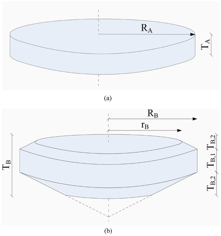
Scheme of an approximation of a conventional circular sawblade (a) and a thinner circular sawblade (b).
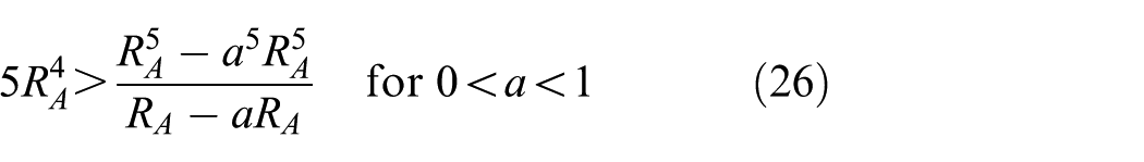
If the geometry of the disc is modified seeking a reduction in the thickness, the moment of inertia can be calculated as the sum of one cylinder and two truncated cones (see Figure 4(b))

where TB,1 and TB,2 are thicknesses of the saw body and RB and rB are the radii (see Figure 4(b)). Without restriction of generality, we will assume that


To demonstrate that a thinner disc will provide a lower moment of inertia, we need to verify the following inequality

which involves demonstrating that

This equation can be simplified as follows

By choosing

we can assume that
which verifies equation (20). This equation can also be simplified by
which can be factorised as follows

It is a trivial verification that equation (28) holds if a is positive and less than 1. Therefore, equation (22) also holds and it has been demonstrated that a thinner disc will provide a lower moment of inertia, and hence, the mechanical power associated with it will be inferior and this means reducing energy consumption.
Based on this formulation, it is possible to make a prediction of the energy consumption gap between a conventional tool and a thinner tool which work under the same cutting conditions. Assume that the conventional tool has a diameter of 356 mm (i.e. RA equal to 178 mm) and a thickness of the saw boy TA of 6 mm. Let us say that we reduce the moment of inertia by reducing the geometry establishing TB,1 of 3 mm (and hence, a value of TB,1 of 1.5 mm) and a diameter for the clamp flange of 328 mm (i.e. RB equal to 164 mm). Using equations (17) and (18), it easy to find that the moment of inertia IA is equal to 0.0738 kg m2 and the moment of inertia IB is equal to 0.0684 kg m2.
In conclusion, it can be said that a reduction of the circumferential thickness of 50.0% together with a reduction of the radius of 7.9% (making a total volume reduction of 26.9%) provides a reduction of the moment of inertia of 7.3% (and hence, a reduction of the energy consumption of 7.3%). This result will be proved experimentally in section ‘Experimental comparison between the commercial and the thinner circular sawblade’.
Explanation of the cutting force reduction
Is it true that a thinner circular sawblade could help to decrease the cutting forces generated during the sawing operation? This question has been studied by Turchetta 14 who initially analysed the relation between the magnitude of cutting forces and chip thickness, which is directly related to thickness of the circular sawblade since using a thinner circular sawblade would provide more space to evacuate sawing swarf and this would result in less friction in the sawing zone. Cutting forces depend on depth of cut, feed speed and width of the cut and this suggests that a thinner circular sawblade would reduce the magnitude of the cutting forces generated during a sawing operation.
Resources employed to conduct the research
The following section describes the available means that researchers employed to perform the investigation. The equipment consists of a cutting machine and the MCS: the cutting machine helped to perform sawing operations, whereas the MCS was used to measure parameters of the sawing process itself. This section also describes the workstation and software used to design the new thinner circular sawblade. Additionally, the characteristics of the samples used for experimentation are shown, and the circular sawblades used for experimentation are described in this section.
Cutting machine AURO 3000-4
This bridge saw machine is suited for one-direction cutting applications and the materials covered are marble, limestone and granite. AURO 3000-4 was selected because it is similar to cutting machines that may be in a natural stone company (see Figure 5).

Cutting machine AURO 3000-4.
This equipment is 4.6 m long, 2.4 m wide and 2.1 m high. The nominal power requirement in operation is 11 kW and the water consumption in operation is 20 L/min (the cutting fluid is important for reduction of cutting forces and to remove heat due to the effect of friction).
This cutting machine is suited for executing three different movements, which are controlled by separate inverter motors: spindle motion (Z-axis), horizontal motion (feed direction, X-axis) and vertical motion (Y-axis). Additionally, this cutting machine is provided with a circular sawblade with 27 teeth, which key characteristics are described in Table 1 and each dimension available in Table 1 is shown in Figure 6.
Geometrical properties of the circular sawblade mounted in the AURO 3000-4.
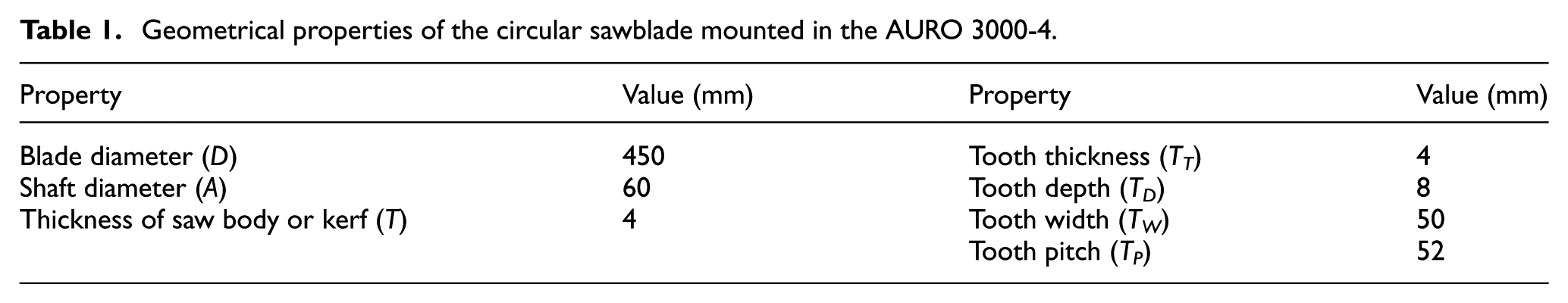
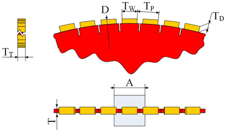
Main dimensions of a circular sawblade.
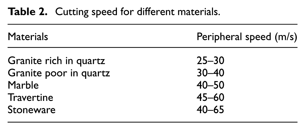
As it is well known, each material has a specific peripheral speed in which best chip removal with fewer cutting forces is obtained. This all-purpose information is available in the documentation of the cutting machine, and it is presented in Table 2.
Cutting speed for different materials.
MCS
The research team designed a multi-axis force measurement system suitable to be set up in a cutting machine (this device can be mounted on any slab/tile cutting machine as long as it has a static baseplate). This system, named MCS, is capable of measuring and monitoring cutting forces generated during a sawing operation, which, combined with other measured parameters such as spindle speed, and cutting time, allows obtaining the total sawing power required; additionally, the MCS also allows measuring parameters directly related to electrical energy consumption. Comparing both energies, researchers are able to calculate the energy efficiency of the sawing. Alongside, that cutting condition data provided by the MCS have helped to study and optimise the circular sawblade. Further information on this device is given in the final degree project carried out by De Paco Soto. 20
How does the MCS work?
As it is shown in Figure 7, this system operates as follows:
During the sawing operation, the sawblade creates cutting forces that act on the stone placed on the platform.
As a result of those forces, the stone puts pressure on the elastic beams connected to the platform which returns results in deformations.
The installed strain gauges change their resistivity depending on the resultant deflections. Basically, the strain gauges transform deformations advent into resistance deviation.
There are two complete Wheatstone bridges installed in each elastic beam that detects changes in the gauges’ resistance (due to voltage unbalance of one of the two legs of the bridge).
Once the bridges notice changes in the voltage in millivolts, a cluster of electronic amplifiers adjusts those quantities into volts. In this manner, the system acquires convenient voltages.
The programmable logic controller (PLC) uses the voltage signals of each electronic amplifier to calculate the cutting forces based on a calibration matrix K.

Explicative scheme of the Maltese cross system functioning.
As a result of the full process, cutting forces are acquired and saved in the storage system of the MCS. Additionally, the MCS has plug-type connections to the frequency converters controlling each inverter motor (spindle, horizontal and vertical motion); these connections provide the MCS with the required information to calculate the parameters related to total sawing and electrical power consumption (spindle speed, cutting time for the sawing component and current, voltage and power factor for the electrical component).
What information does the MCS provide?
The MCS is capable of measuring the following parameters:
Sawing power, PS:
Cutting force, FC; Spindle speed, ω; Feed rate; Cutting time.
Electrical power, PE:
Current output, I; Voltage output, V; Power factor, cos(φ).
The first group of parameters can be used in the above-mentioned equation (12) since the sawing power PS can be expressed as follows

and the radius of the circular sawblade is R which can be introduced as input into the PLC. The second group of parameters allows to calculate the electrical power PE as

Using equation (29) and equation (30) we can obtain the global efficiency η, which can be defined as

Development of the MCS
First of all, a previous design of the MCS is carried out via computer-aided design (CAD) which resulted in a digital prototype provided with dimensions, materials and standard parts (see Figure 8(a)). The MCS consists of a static baseplate with strain gauges arranged in a cross. This configuration allows to acquire deflections generated during the sawing process. Researchers extrapolated the design performed by Kim et al. 21 that proposed a four-beam structure capable of measuring the three components of a force. To summarise, researchers selected a configuration in which a pair of strain gauges is placed in each of the four faces of the elastic beams.
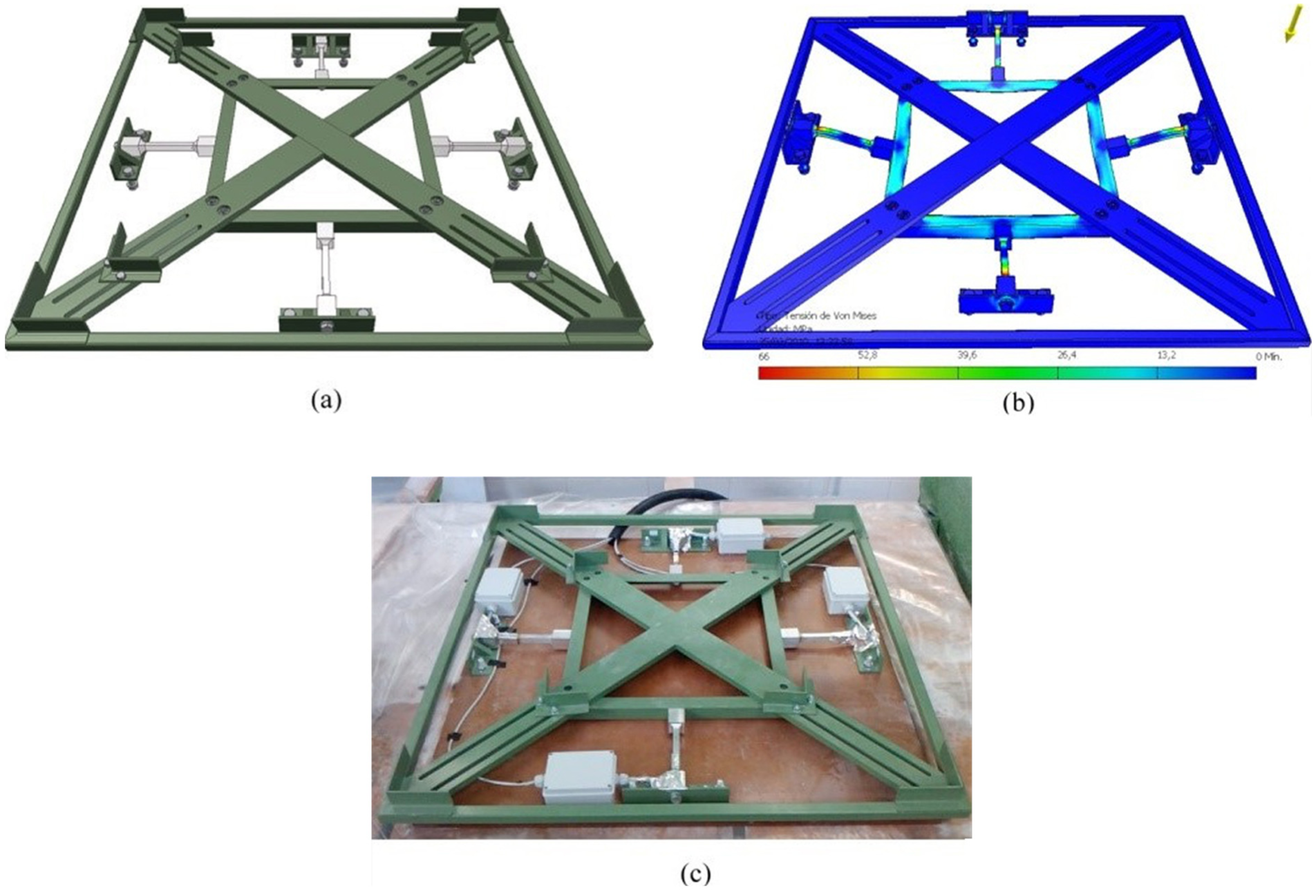
Maltese cross system: (a) digital prototype, (b) Von Mises stresses and (c) installed system.
The digital prototype of the MCS was validated using FEA in order to confirm whether all the elements within the assembly could resist the operation requirements. Figure 8(b) shows an example of the Von Mises stresses detected where a maximum value of 260 MPa appears in the screws connecting the four beams to the static baseplate (this involves a factor of safety of 2.5 which also was the minimum factor of safety detected). Additionally, the system was simulated using FEA with the purpose of verifying the behaviour of the device during a sawing operation and with the intention of virtually calibrating the strain gauges.
The gauges were installed in the elastic beams using Wheatstone Bridge configuration (Figure 9(a) shows the configuration of the strain gauges and how they were installed). The corresponding electrical wiring was also prepared. Once the rest of the components of the system were manufactured, they were also assembled and all the connections of the electronic amplifiers were carried out (see Figures 8(c) and 9(b)). The PLC was programmed using a supervisory control and data acquisition (SCADA) in order to provide a human-machine interface that would allow for monitoring the measuring process. The selected controller (Siemens S7-200) allows reading the analogical signal coming from the strain gauges, to communicate with the control system of the motors and to monitor all the involved variables via SCADA. Finally, the communication architecture required to link all the components was designed and implemented.

Maltese cross system: (a) detail of the strain gauges and (b) detail of the electronic configuration.
Workstation and software
An HP Z400 workstation was the equipment used to perform the design and simulations. The main characteristics are as follows:
Operative system: Microsoft Windows® XP Professional 64 Edition Version 2003 SP 2.
Processors: Intel Xeon W3520, 2.66 GHz, 8 MB cache, Quad-Core, HT, Turbo.
Memory: 6 GB DDR3-1333 ECC Unbuffered RAM 1-CPU.
SolidWorks 2015 was the software package utilised to create the CAD design and SolidWorks 2015 Simulation Premium was the module to simulate the mechanical performance of the cutting phenomenon.
Commercial diamond segmented circular sawblade
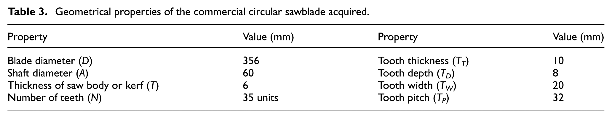
The assessment of the results provided by this research needed to be referenced to a commercial circular sawblade and compatible with the AURO 3000-4. The characteristics of this circular sawblade are described in Table 3. Researchers used this set of values as a starting point for the design process.
Geometrical properties of the commercial circular sawblade acquired.
Samples
The samples are square-shaped slabs of natural stone. The characteristics of the samples are shown in Table 4. The maximum deflection value taken into account was 0.1 mm due to technical specifications of the Crema Marfil Marble.
Properties of the natural stone samples.

Experimentation with the already mounted circular sawblade
Two groups of tests with different cutting conditions were carried out to measure parameters of the sawing process and also determine the effectiveness of the MCS to optimise the parameters of a sawing process (these parameters will be required for simulation). Each sawing operation was performed using the cutting machine AURO 3000-4 equipped with the already mounted circular saw and using the samples described above. An experimental test is shown in Figure 10.
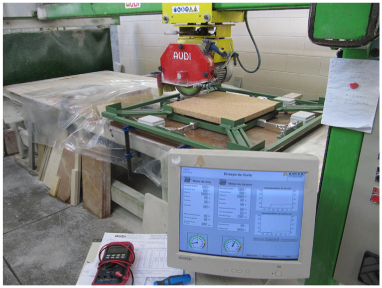
Performing a sawing operation and measuring data using the Maltese cross system.
A group of 10 tests was based on the configuration of parameters recommended by the manufacturer AUDI and another group of 10 tests was performed with a configuration with higher global efficiency η, which was defined by equation (31).
The second group of parameters was obtained as a result of changing feed rate and spindle speed seeking the maximum global efficiency of the sawing operation (both groups of parameters are shown in Table 5).
Cutting conditions used in the two groups of experimental tests.
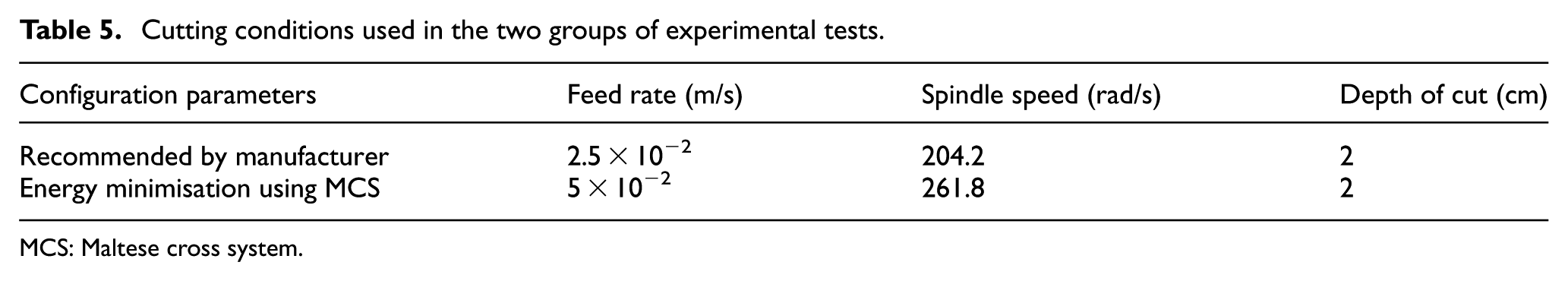
MCS: Maltese cross system.
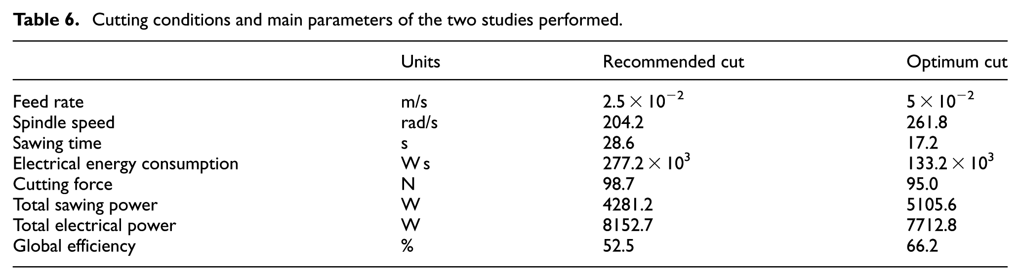
The optimum configuration relative to recommended configuration by the manufacturer increases the global efficiency from 52.5% to 66.2% and reduces electrical energy consumption and sawing time by two.
Consequently, two cutting conditions of the circular sawblade were obtained (see Table 6). From these cutting conditions, the values related to the cutting force and spindle speed were taken into account during the simulation stage.
Cutting conditions and main parameters of the two studies performed.
Simulation design
First, a simulation of the commercial circular sawblade is implemented using the information from the experimental tests. Then, the geometry is optimised seeking to reduce the moment of inertia and to obtain a thinner circular sawblade. This new design was evaluated by simulating it under cutting conditions obtained experimentally and changing the geometry while the mechanical performance was within the suitable functioning limits. As it has been demonstrated theoretically, this design shall overcome efficiency problems.
Simulation of the commercial circular sawblade
This stage begins modelling a digital prototype of the commercial circular sawblade previously acquired (see dimensions and geometry in Table 3 and Figure 6); it is modelled using the CAD module available in SolidWorks (see Figure 11). Once the three-dimensional (3D) model has been created, the next step is analysing its mechanical performance under the cutting conditions already measured; this analysis can be done through a simulation carried out in the FEA module available in SolidWorks.
Digital prototype of the commercial circular sawblade.
At this point, it is necessary to simplify the 3D model and to accelerate the simulation process; that is why only a triangle-shaped portion is taken into account in the simulation study (see Figure 12). Using the cutting conditions and studying the morphology of the problem, it is possible to define material properties, loads and constraints that represent the effect of the environment on the model. Additionally, meshing should also be defined properly in order to provide accurate results.

Triangle-shaped portion of the 3D model including boundary conditions.
Materials properties
Upon request, the manufacturer of the commercial circular sawblade provided its material properties: Young’s modulus of 205 GPa, Poisson ratio of 0.28 and yield strength of 250 MPa.
Restraints
The applied restraints are a fixed geometry (blue faces in Figure 12) and a circular symmetry (green faces in Figure 12). On one hand, the cylindrical face of the circular sawblade related to the rotating shaft has all translational and all rotational degrees of freedom restrained. On the other hand, the symmetry used in the cut faces of the triangle-shaped portion allows simulating as if the tool is complete (in the case of modal analysis, the complete 3D model is used).
External loads
Let us remember that the MCS provides the parameters of the sawing process (available in Table 6). The external loads considered are (lilac and red arrows shown in Figure 12, respectively):
The cutting force is 98.7 N (maximum force value between the recommended cut and the optimum cut, see Table 6).
The spindle speed is 261.8 rad/s (maximum spindle speed value between the recommended cut and the optimum cut, see Table 6); the performance and the deviation of the tool are analysed by variation of the spindle speed.
Meshing
The created mesh is based on curvature and a total number of nodes and elements are 62,408 and 40,828, respectively. The element size is 1.40 mm with a tolerance of 0.07 mm, which results in an average tetrahedron volume of 0.37 mm3. As a result of this mesh configuration, the percentage of elements with an aspect ratio lower than 3 is 99.50% and the percentage of elements with an aspect ratio higher than 10 is 0.04%. So the aspect ratio can be specified as the relation between the edge with longer length and the edge with shorter length. All this information can be found in Table 7 and also graphically represented in Figure 13.
Meshing details and properties.


Mesh used in FEA simulation.
Results
By FEA simulations, different results were obtained by applying a variable spindle speed from 0 to 261.8 rad/s and a cutting force of 98.7 N as external loads. The results described below are stresses, deflections and modal response.
Values of Von Mises stresses are under the yield strength of the material (250 MPa). If the circular sawblade runs under high cutting speed, the stiffness increases (see Figure 14).

Von Mises stresses and spindle speed of the commercial circular sawblade.
Deflection rises by increasing the spindle speed and the absolute value of deflection at approximately 261.8 rad/s is 3.95 µm (see Figure 15) which is lower than the maximum deflection the material can withstand (see Table 4).
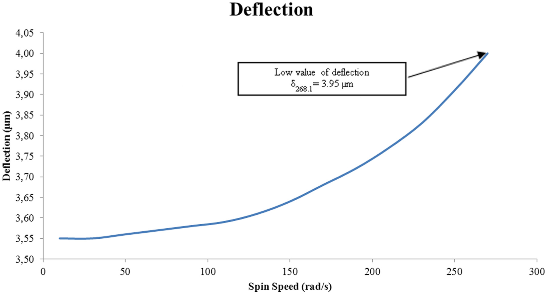
Deflections and spindle speed of the commercial circular sawblade.
The value of the eigenfrequency increases with spindle speed (see Figure 16). The minimum value is 666.4 Hz (4187 rad/s) which is far away from the maximum value settable in the sawing machine. Hence, the cutting machine will not experience resonant effects.

First resonance mode and spindle speed of the commercial circular sawblade.
Design and simulation of the thinner circular sawblade
The next stage consists of analysing the mechanical performance of a thinner circular sawblade. In reference to the simulation configuration parameters, it is worth mentioning the use of increasing factors of 2 applied to external loads and a reduction factor of 1.25 applied to the yield strength. For the decision process, a safety factor of 4 was taken into account, which means a Von Mises stress maximum of 50 MPa. Those factors define the load carrying capacity of the circular sawblade beyond the expected or actual loads.
On the other hand, the parameter slope, S, was defined to assess the change in the geometry circular sawblade (see Figure 17). This parameter may be calculated as
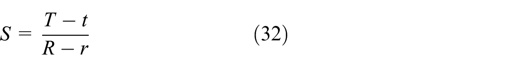
T is the maximum thickness of the plate of the tool (6 mm, see Table 3), t is the minimum thickness of the plate of the tool (6 mm or lower, see Table 3), R is the radius of the tool (356 mm, see Table 3) and r is the radius of the clamping flange (for the AURO 3000-4, this value is 100 mm). Another variable studied was the tooth thickness (10 mm or lower, see Table 3), L. During simulation, values of S and L were changed seeking the optimisation in the geometry.

Representation of the variables associated with the slope.
Materials properties
Since a reduction factor of 1.25 is applied to the yield strength, this leads to a value of 200 MPa. Additionally, a safety factor of 4 is taken into account in order to include the load carrying capacity of a system beyond the expected or actual loads (which means a maximum Von Mises stress of 50 MPa). Both Young’s modulus and Poisson’s ratio are defined as in the previous simulation.
Restraints
The applied restraints are the same as before, a fixed geometry (blue faces in Figure 12) and a circular symmetry (green faces in Figure 12).
External loads
Since an increasing factor of 2 is applied to external loads, the considered values for cutting force and spindle speed are as follows:
The cutting force is 197.4 N.
The spindle speed is 523.6 rad/s.
Meshing
The mesh generated to analyse the thinner circular sawblade has similar properties as before.
Results
After running various simulations, different results were obtained by changing the tooth thickness, L, from 4.0 to 10.0 mm and also the thickness of the plate of the tool, T, from 5.5 to 1.0 mm. In terms of slope, each value gives a value of the slope (see Table 8).
Values for thickness of the plate of the tool and slope.
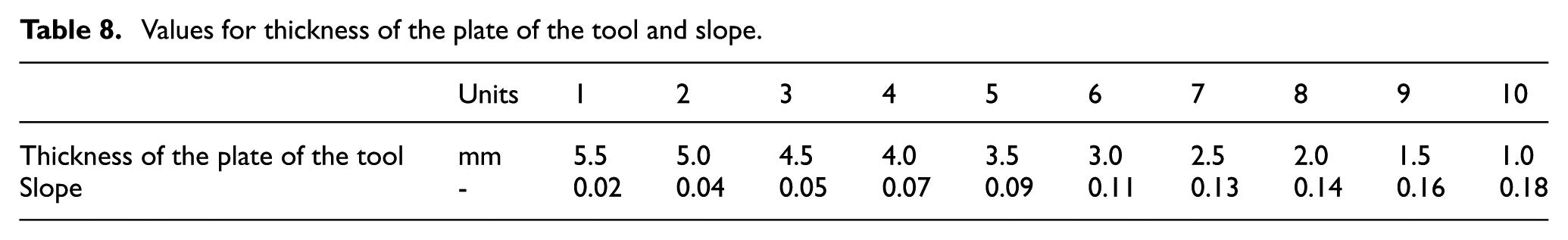
Von Mises stresses increase with slope (see Figure 18). The value of 49.8 MPa appears when t is equal to 3 mm and L is equal to 9 mm (see Figure 18). Von Mises stresses fall by decreasing thickness of the teeth, but the minimum permissible value is 6 mm because the union between the planar face and tooth has to be bigger than 1.5 mm (manufacturer recommendation).

Von Mises stresses with regard to slope and tooth thickness of the thinner circular sawblade.
Deflection rises with slope (see Figure 19). The maximum value of deflection reaches 8.3 µm (see Figure 19) which is below the maximum deflection (see Table 4).

Deflections with regard to slope and tooth thickness of the thinner circular sawblade.
The eigenfrequency decreases by increasing slope but the minimum value is 536.1 Hz (see Figure 20) which is far away from the maximum settable spindle speed value in the sawing machine and, hence, the cutting machine will not experience resonant effects.

First resonance mode with regard to slope and tooth thickness of the thinner circular sawblade.
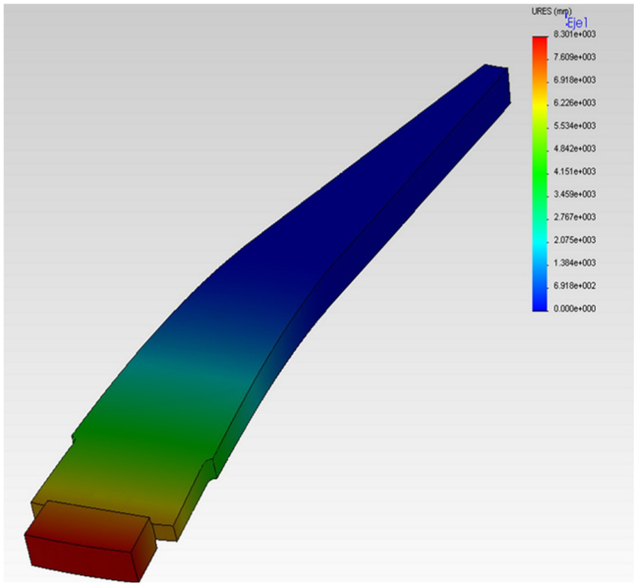
As a result of the simulation process, the thinner circular sawblade selected has T of 6 mm, t of 3 mm and L of 6 mm. The results are as follows: Von Mises stress of 47.3 MPa (see Figure 21), deflection of 5.7 µm (see Figure 22) and eigenfrequency of 728.5 Hz (see Figure 23).

Simulation results: Von Mises stress.
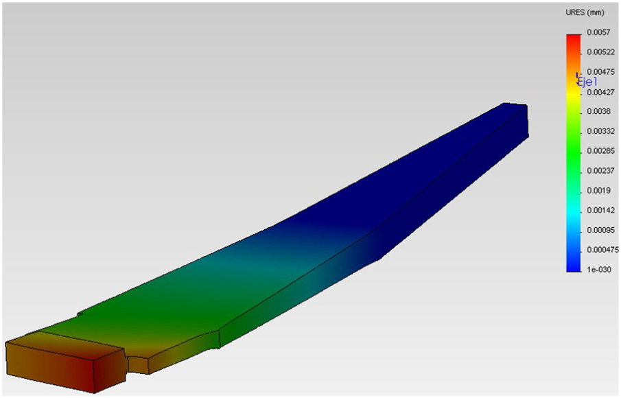
Simulation results: deflection.
Simulation results: the first resonance mode.
Comparison between the commercial and the thinner circular sawblade
The commercial circular sawblade simulated with a cutting force of 98.7 N and a spindle speed of 261.8 rad/s involved a maximum Von Mises stress of 27.9 MPa (lower than 50 MPa) and a maximum deflection of 3.9 µm (lower than 0.1 mm). The new circular sawblade simulated with a cutting force of 197.4 N and a spindle speed of 523.6 rad/s involved a maximum Von Mises stress of 47.3 MPa (lower than 50 MPa) and a maximum deflection of 5.7 µm (lower than 0.1 mm). This issue is summarised in Table 9.
Comparison between the commercial and the thinner circular sawblade.

Experimental comparison between the commercial and the thinner circular sawblade
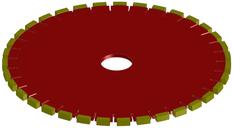
As already stated, two units of a commercial diamond segmented circular sawblade were acquired. Those tools had a maximum thickness of the plate of 6 mm, a radius of 356 mm and a thickness of the tooth of 10 mm (see Figure 24(a)). One of them was manufactured as pointed out in the presented thinner design (see Figure 24(b)).

Commercial circular sawblade (a) and thinner circular sawblade (b).
Once the thinner circular sawblade was mechanised, 30 experiments for each circular sawblade (in this way, 60 experiments would provide the correct repeatability and reliable results) were carried out in order to assess the forces generated during the sawing operation and the power consumption. Tests with the same cutting conditions were carried out. Those tests were based on the configuration of parameters recommended by the manufacturer (sawing depth of 2 cm, feed rate of 2.5 × 10⁻² m/s, spindle speed of 204.2 rad/s and an approximated operating time of 30 s, see Table 5). Those cutting operations were performed in the cutting machine AURO 3000-4 using slabs of Crema Marfil Marble (thickness of 2 cm and length of 60 cm, see Table 4). As a result of the experimentation, two important findings related to forces and consumptions were discovered. This will be presented in the two following points.
Cutting force results
The MCS provided information about the cutting forces required to manufacture the natural stone slabs. During the tests, the variable of interest analysed using this device was the cutting force (see Figure 25).

Average force applied during all the tests using both types of circular sawblades.
The sawing operations performed with the thinner circular sawblade applied 6.20% less force than those executed with the commercial circular sawblade (in average). Since the geometry of the thinner circular sawblade provides more space to evacuate sawing swarf, this results in less friction in the sawing zone which explains the experimental reduction in the cutting forces generated (explained in section ‘Explanation of the cutting force reduction’). As it is shown in Figure 25, the average force for the thinner circular sawblade is 117.88 N and for the commercial circular sawblade is 125.19 N. Based on equation (12) using spindle speed of 204.2 rad/s and a radius of 356 mm, the average in total sawing power in the first case is 4284.66 W and in the second case is 4550.35 W.
Electrical power results
During the tests, several variables of interest were analysed. Among other variables, the total electrical power was studied using the plug-type connections to the frequency converters controlling each motor, and it provided information about voltage values on the terminals of the machine, the amount of current in the electrical circuit, power consumption and power factor.
The sawing operations performed with the thinner circular sawblade consumed 9.87% less electrical energy than those executed with the commercial circular sawblade (in average). As it is shown in Figure 26, the average total electrical power for the thinner disc is 6072.18 W and for the commercial disc is 6737.07 W. Additionally, the global efficiency of the sawing operations performed with the thinner circular sawblade is about 70.6% while those performed using the commercial circular sawblade have a global efficiency of 67.5%.
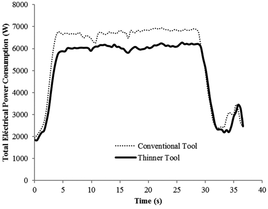
Average total electrical power during all the tests using both types of circular sawblades.
Conclusion
The energy diagnostic confirmed the importance of sawing processes within the natural stone production chain. This finding guided the research in the direction of improving diamond segmented circular sawblades. The energy required to spin a circular sawblade is related to its mass and geometry, so a thinner circular sawblade reduces energy consumption (lower moment of inertia).
The MCS permitted to measure forces generated during the sawing process as well as energy consumption (and hence, global efficiency). Tests conducted with the equipment available provided the cutting conditions for an optimum configuration with feed rate of 5 × 10⁻² m/s, spindle speed of 261.8 rad/s and, therefore, sawing time of about 17.2 s, which involves a global efficiency of 66.2%. The MCS also provided the value for the cutting force of 98.7 N which was also used to configure the simulation to validate the design of a thinner circular sawblade.
Once two units of a commercial diamond segmented circular sawblade were acquired, researchers used the FEA module available in SolidWorks to simulate the mechanical performance of the commercial circular. The results showed that the mechanical performance reached values within appropriate and safe structural limits:
Maximum Von Mises stress: 27.9 MPa;
Maximum deflection: 3.9 µm;
First resonance mode: 666.4 Hz.
A thinner circular sawblade was designed based on the initial geometry seeking to reduce the moment of inertia. In this case, the simulation was configured using more demanding cutting conditions. The simulations helped to find an optimal configuration: thickness of the plate of the tool of 3 mm and tooth thickness of 6 mm. The results showed that the thinner circular sawblade also reached proper values:
Maximum Von Mises stress: 47.3 MPa;
Maximum deflection: 5.7 µm;
First resonance mode: 536.1 Hz.
As a conclusion, the thinner circular sawblade designed is appropriate to operate in worse conditions than the commercial circular sawblade. Even though the thinner disc was subject to severe cutting conditions and presented higher values of maximum Von Mises stress and deflection (and a lower first resonance mode), those parameters were within the suitable limits.
One of the two units of the commercial circular saw was mechanised as the thinner design. Then, several experimental tests were performed using the commercial as well as the thinner circular sawblade and the equipment available. As a result of those tests, two important findings were exposed. The thinner sawblade needed a 6.20% less force than the commercial and, hence, less total sawing force. The sawing operations performed with the thinner circular sawblade consumed 9.87% less energy than those executed with the commercial circular sawblade.
In the first case, the thinner circular sawblade provides a drop in the cutting force. This reduction in the amount of force also involves saving in maintenance costs and extending the life cycle. Moreover, as the thinner circular sawblade is finer than the commercial circular sawblade, the sawing operation can be carried out wasting less material and consuming less amount of energy. In this way, a more efficient sawing operation can be performed using the thinner circular sawblade than the commercial circular sawblade.
In the second case, the thinner circular sawblade provides a drop in total electrical power. This reduces the electrical bill and also the production costs. Requiring less than total electrical power (so that the needed power to move the circular sawblade is smaller by decreasing the weight and the moment of inertia) supports the argument that the thinner circular sawblade will have an impact on environmental issues and embedded energy related to sawing processes in natural stone industries.
Additionally, it is important to mention that a reduction of the moment of inertia of 7.3% should provide a theoretical reduction of the energy consumption of 7.3% which is similar to the value obtained experimentally. Moreover, the reduction is bigger for total electrical power than for total sawing power. This means that the thinner circular sawblade provides higher values for the global efficiency (70.6%) than the commercial circular sawblade (67.5%).
Footnotes
Appendix 1
Handling Editor: Xiao-Jun Yan
Declaration of conflicting interests
The author(s) declared no potential conflicts of interest with respect to the research, authorship, and/or publication of this article.
Funding
The author(s) disclosed receipt of the following financial support for the research, authorship, and/or publication of this article: The authors gratefully acknowledge financial support from the European Commission (project reference LIFE08 ENV/E/000126).