
Abstract
With the increasing demand for metal foil parts with micro-array structures in micro-electromechanical systems (MEMS), it is urgent to explore a novel array micro-forming technology with high efficiency, low cost, and high flexibility. The cavitation water jet uses the high-energy shock wave generated by the collapse of the cavitation bubble group as the loading force. It has the characteristics of large range of action, uniform pressure distribution, and can realize large-area array micro-forming processing. To verify the feasibility of cavitating water jet array micro-forming, this paper performs cavitating water jet array micro-forming on 304 stainless steel foil with a thickness of 80 μm, and analyzes the variation of cavitation bubbles collapse impact zone with target distance. The effects of target distance and impact time on the forming quality of metal foil array micro-holes were studied from the aspects of forming depth, surface roughness, and thickness thinning rate. The results show that the forming depth and uniformity of the array micro-holes located in the cavitation collapse area increase with time. However, with the increase of target distance, the forming depth increases first and then decreases. When the target distance is L = 120 mm, the forming depth reaches the maximum. The surface roughness (Ra) of the array micro hole is Ra = 1.54 μm. The thickness thinning rate of the micro-forming parts is between 2% and 10%, and the maximum thickness thinning rate in the die fillet area is 13.5%. This paper provides a novel processing method for manufacturing metal foil parts with micro array structure.
Introduction
With the rapid development of micro-electro-mechanical systems, metal foil parts with micro-array structures are increasingly utilized in electronic information, aerospace, rail transport, biomedical, and other fields. 1 However, traditional microfabrication technologies, such as microfabrication electric discharge machining, ultra-precision machining, deep reaction ion etching, etc. They face challenges like low efficiency, susceptibility to contamination, process complexity, and high cost, which restrict their widespread application in microfabrication. 2 In contrast, plastic micro-forming technology has the advantages of high efficiency, precise forming, and superior processing quality. Consequently, it has found extensive use in the processing and manufacturing of microfine parts. 3
Plastic micro-forming is a microfabrication technology that utilizes plastic deformation methods to form micro components. Rhim et al. 4 achieved the formation of micro holes with a diameter of 2 μm micro holes in a copper foil with a thickness of 3 μm and a titanium foil with a thickness of 1.5 μm using miniature rigid molds. However, challenges such as difficult mold fabrication, high frictional resistance, and complex positioning due to miniaturization have significantly hindered the industrialization of traditional micro forming technologies.5,6 To address these challenges, numerous researchers have begun to explore the application of flexible media such as laser, electromagnetism, and liquid in micro-forming technology. Justinger et al. 7 utilized laser shock waves as a loading means to fabricate microcap shaped copper parts with a thickness of 15 μm. Li et al. 8 employed laser impact to form micro gear holes on brass foils with thicknesses ranging from 20 to 60 μm and investigated the effects of laser energy and grain size on the quality of the formations. Zhao et al. 9 applied electromagnetic micro-forming to create a microchannel structure on 100 μm T2 Cu foil and investigated the effect of different voltages on forming depth and width. Huang et al. 10 successfully stamped micro-holes with diameters ranging from 2 to 16 mm in 100 μm titanium foil using electromagnetic micro-forming technique and numerically simulated the dynamic process. However, these micro-forming techniques are challenging to adapt to batch and flexible production due to the disadvantages of complex manufacturing processes, long cycle times, significant investment requirements, environmental pollution, poor reproducibility, and the inability to manufacture metal foil parts with large-area micro-array structures. Therefore, there is an urgent need to explore a novel metal foil array micro-forming technique to address the current challenges in the micro-forming field.
When the high-speed water jet passes through the nozzle, it forms a large number of cavitation bubbles carrying cavitation water jets. As the bubble group moves toward the near-wall surface, it collapses intensively, resulting in high temperature, high pressure, shock waves, and micro-jets. 11 Its energy is highly concentrated, capable of generating very high impact pressure in localized areas on the target material surface. Consequently, many scholars have applied cavitation water jet technology to various fields such as workpiece surface strengthening, 12 polishing, 13 and rock breaking. 14 Among them, the study of Soyama 15 is the most representative on cavitation water jet peening of copper, aluminum, and stainless steel. It delves into the influence of nozzle structure, injection pressure, and target distance on the microstructure of materials and achieves highly satisfactory results. Tsuda et al. 16 utilized cavitation water shot peening in combination with quenching treatment to strengthen spiral gears made of carbon steel, forming a 100 μm deep reinforced layer and residual compressive stress of 600 MPa. Conn and Johnson 17 invented submerged cavitation water jet nozzles and used the nozzles for rust removal experiments on iron blocks, effectively removing rust. Soyama and Saito 18 studied the forming process of hard aluminum sheet with a thickness of 3 mm by using cavitation water jet with a pressure of 20 MPa, and obtained a test piece with a radius of curvature of 4.1 mm. Therefore, the application of cavitation water jet technology to micro-forming processing offers the following advantages: (1) The uniform load of the cavitation bubbles on the surface of the foil during the forming process is beneficial to obtain relatively uniform deformation. (2) The area where the cavitation water jet concentrates and collapses near the wall forms an annular area with a broad range of impact force action. (3) This technique has the characteristics of low cost, green, high efficiency, strong applicability, and no need for rigid punch. The above study demonstrates that cavitation water jet can be utilized for array micro-forming processing of metal foils.
Based on the characteristics of large impact range and uniform pressure distribution of cavitating water jet, this paper innovatively loads cavitating water jet on metal foil and studies the feasibility of impacting metal foil array micro forming. Therefore, in this study, an array die with micro-hole structure was designed, and the micro-forming of 304 stainless steel foil array was carried out by using a cavitation jet micro-forming device. The effects of target distance and time on the quality of array micro-hole formation were analyzed from the aspects of forming depth, surface roughness, and thickness thinning rate, and the feasibility of the process was verified. It provides a novel processing method for manufacturing metal foil parts with micro-array structure.
Methodology
Structural parameter design of submerged cavitation water jet nozzle
The nozzle is crucial to producing cavitation for the cavitating water jet. In this paper, the self-excited oscillating organ pipe nozzle is combined with the triangular nozzle, which vastly enhances the shear effect, and the mixed nozzle is designed with a more substantial cavitation effect.
According to the theory of the converging nozzle, the diameter of the mixed throat is

where Q is the inlet flow rate of the nozzle, P is the incident pressure, K is the correction factor of the nozzle, M is the outlet number of the nozzle.
The rated volume flow Q of the pump is 14 L/min, the rated pressure P is 20 MPa, the coefficient K is 0.6, the number of nozzle holes M is 1, and the diameter d of the mixed nozzle throat is 1.6 mm in this experiment.
Natural frequency of the nozzle cavity f depends on the inlet section ratio (DS/D) 2 and the outlet section ratio (D/d) 2 , where DS is the diameter of the inlet cavity and D is the diameter of the resonant cavity:

where KN, L, and a are the modulus coefficient, the length of resonant cavity, and the disturbance wave velocity of the resonant cavity, respectively.
The modulus coefficient KN is

where N is the oscillation modulus of the resonant cavity, N is 1, the inlet section ratio (DS/D) 2 is 3.5–4.5, the outlet section ratio (D/d) 2 is 10–11.
When the natural frequency f of the mixing nozzle cavity is equal to the critical self-excited frequency f*, the strongest resonance will occur. If the nozzle length is not limited, f* is taken as a small critical Strouhal number

where Ma is the Mach number.
The most intense resonance occurs in the mixing nozzle with the strongest resonance, which should meet the following requirements:
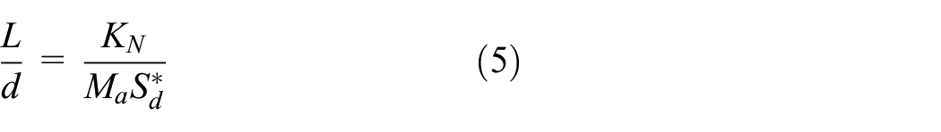
Figure 1 shows the structure of the mixing nozzle used in the experiment, and the expansion angle α of the common triangular nozzle is 40°. The length l of the mixing nozzle is 4 mm and the diameter d of the mixing nozzle is 1.6 mm.

(a) Schematic diagram of nozzle structure and (b) physical drawing of nozzle.
Experimental device of submerged cavitating water-jet impingement
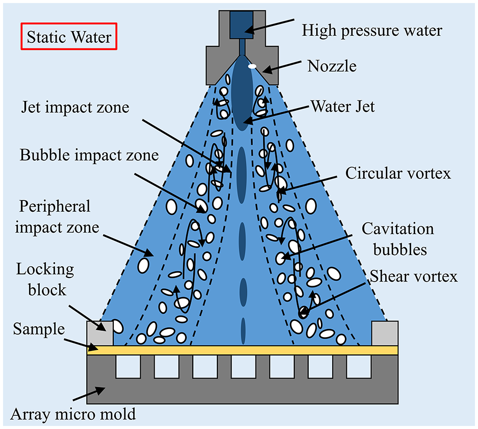
Figure 2 illustrates its working principle according to the theory of cavitation water jet. The cavitation water jet impact zone can be divided into three areas: jet impact zone, cavitation impact zone, and peripheral impact zone. The high-speed jet from the nozzle is blocked by the surrounding liquid, the velocity of jet is decreasing and few vacuoles are found in the middle of the jet due to the small pressure change. The impact pressure on the workpiece in the water jet impact zone is vastly reduced. The external jet and dynamic jet shear strongly with the surrounding static water outside the center. The pressure obviously changes, the number and development of cavitation are abundant. The workpiece in the bubble impact zone will be subjected to the huge impact pressure of the collapse of the cavitation bubble group. Although a few vacuoles are outside the bubble impact zone, it diffuses outwards with the jet flow, and its effect on the material is limited.19,20 Therefore, the impact pressure of the peripheral impact zone is much smaller than that of the bubble impact zone. There is no strict boundary between the three impact zones as the cavitation water jet is affected by nozzle shape, complex conditions, equipment, and target distance.
Schematic diagram of foil array micro-forming impacted by submerged cavitating water jet.
Figure 3 is a schematic diagram of the cavitation water jet impact micro-forming experiments. The system mainly includes the cavitation generation device, external equipment, and forming device. The cavitation generator primarily consists of a high-pressure piston pump, a pressure valve, and a cavitation nozzle; the external equipment mainly consists of a large water tank, a transparent water tank, a workpiece clamping device, and an electrical cabinet. The forming apparatus is a self-designed micro-forming mold assembly, which mainly includes a locking block, mask, workpiece, and micro mold. The forming unit is fixed on a workbench and placed in a transparent water-filled tank. The working process of the cavitation water jet impact micro-forming experimental system is as follows: tap water is delivered to the cavitation nozzle by a high-pressure piston pump and then injected vertically into the transparent tank containing water to produce a cavitation water jet. The main composition of the experimental system is illustrated as shown in Figure 4. TW-5570 ultra-high-pressure plunger pump is used as the high-pressure pump station. The acrylic resin water tank of 1000 L contains purified tap water at 25°C ± 2°C stored for at least 24 h.

Schematic diagram of cavitation water jet experiment.

Water-jet cavitation experimental system.
The array experiment of the micro-forming die is carried out on an annular array blind-hole with a diameter of Φ1.2 mm × 3 mm and made by micro EDM. Its structure is illustrated in Figure 5, and the self-designed array micro-forming fixture structure used in the experiment is presented in Figure 6. To ensure that the submerged cavitating water jet is not disturbed by the free surface, the distance between the vertical downward nozzle and the free surface of the water tank top is set to more than 300 cm. Referring to the previous experience of the cavitation water jet shot peening optimal target distance, 21 the target distance is 100–140 mm, and the impact loading time is 1–5 min. The submerged cavitating water jet impinges on the target in three annular regions, the water jet impact zone within a certain range of the jet center, the adjacent impact zone of cavitation collapse, and the surrounding impact zone. When the incident pressure is 20 MPa, the action time is 5 min and the distribution of three annular regions of 2Al2 aluminum alloy with the change in target distance under the impact of cavitating water jet is roughly distributed as shown in Figure 7.

Shape and dimensions of the micro-mold: (a) Structure size of micro mold, and (b) Three-dimensional model.

Array micro-forming fixture.

Distribution of the impinging area of submerged cavitating water jet with the change in target distance: (a) S = 70 mm, (b) S = 80 mm, (c) S = 90 mm, (d) S = 100 mm, (e) S = 110 mm, (f) S = 120 mm, (e) S = 130 mm, and (h) S = 140 mm.
Experimental results and analysis
Cavitation water jet array micro-forming
The plastic array micro-forming experiment was carried out on a 304 stainless steel foil with a thickness of 80 μm, length of 60 mm, and width of 60 mm under the condition of a 120 mm target distance and 5 min action time. The macroscopic topography of the workpiece was observed by a three-dimensional microscope with super depth of field, which marks and measures the size of the workpiece. The surface roughness of the samples was analyzed by microscope. Its maximum acquisition speed is 100 frames per second, with 3D topography imaging capability, and the scanning resolution can reach 1028 × 1024.
The three-dimensional image of the impact of Figure 8(b) is randomly selected in the impact zone of vacuole collapse in Figure 8(a). Its cross-section shows a smooth profile, and the forming depth is uniform. No crack exists on the surface of the formed hole, and no wrinkle forms around the hole. Figure 8(c) is a two-dimensional profile of all array micro-holes of a–f in the L1 direction in Figure 8(a). The forming depth of micro-holes a and i in the Periphery impact zone and micro-holes e and f in the water jet impact zone is not large. The b–d and g–i micro-holes on the impact zone of cavitation bubbles collapse have suitable shapes, and the uniformity of forming holes and the consistency of the maximum forming depth are good. Good shape and surface quality can be obtained by this method for the foil plastic array micro-forming. In the micro-forming of cavitation water jet array, the forming force of the workpiece comes from the high-energy shock wave of the collapse of the cavitation bubble group. The workpiece located in the bubble impact zone can be affected by a large number of cavitation groups. Therefore, the forming depth of the workpiece in this area is the largest.

Plastic array micro-forming of the 304 stainless steel foil: (a) macroscopic morphology of the sample, (b) three-dimensional topography of hole, and (c) micro-hole contour map in L1.
Effect of impact time on the micro-array forming
The impact time is one of the critical parameters for the metal foil plastic array micro-forming by cavitating water jet. Therefore, the control target distance is 120 mm, and the inlet pressure is 20 MPa. The average depth and depth variance of 304 stainless steel for all holes in the cavitation collapse impact zone is obtained with the curve of changed impact action time.
With the increase in impact action time, the depth of the micro-hole increases, and the variance decreases, as shown in Figure 9. When the impact time was 1 min, the depth of the micro-hole was only 68.5 μm. However, when the impact time reached 5 min, the depth of the array micro-holes was increased to 159 μm. This phenomenon is due to the increase in time. The cavitation collapse and impact at the same position accumulate continuously, with the variation rule of array micro-holes depth increasing and a surfacing variance that decreases with time. When the impact time increased from 1 to 2 min, the array micro-holes depth increased by 34.5 μm. However, considering that the cavitation bubbles collapse impact will produce an impact-strengthening effect on the sample’s surface, the depth of the array micro-holes only increased by 12 μm in the process from 4 to 5 min, with an increased forming difficulty.

Influence of cavitation water-jet impact time on forming depth and variance.
Aiming at the impact time of the array of micro-holes at different positions in the cavitation water-jet cavitation collapse impact zone on the depth and variance of the micro-holes, the arrays of micro-holes b, c, and d in Figure 8(a) are selected as the research objects, and its radii are respectively r = 10.2, 13.6, and 17 mm. Its mean and variance are taken to obtain the variance of array micro-hole depth at different radii in the vacuoles collapse impact region, which varies with the impact time as shown in Table 1.
Average forming depth and standard deviation variation with forming time at the stand-off distance of 120 mm.

Increasing the impact time is also helpful for improving the uniformity of the forming depth of the foil array micro-holes, and the array micro-holes at r = 13.6 mm have immense depth and more uniform forming depth. Because this corresponds to the position of the shear layer cavitation vortex ring, the cavitation moves rapidly downstream. It collapses here, which is consistent with the research results in the literature. 22
Effect of the target distance on the array micro-forming
The target distance of impact is another important parameter for the plastic array micro-forming of metal foil with the cavitating water jet. Therefore, with the control pressure of 20 MPa and the impact time of 5 min, the average depth value and depth variance of all holes formed in the 304 stainless steel foil in the cavitation collapse impact zone are obtained, as shown in Figure 10.

Influence of the standard distance on the forming depth and variance.
With the increase in target distance, the depth of array micro-holes first increases and then decreases, as shown in Figure 10. When the target distance is S = 120 mm, the micro-hole depth is better than other target distances, and the variance of micro-forming depth under different target distances is similar. Still, the variance is slight when the target distance is 120 mm. The main reason is that when the target distance is 120 mm, many cavitation bubbles are in the stage of concentrated collapse. When the target distance exceeds 120 mm, the cavitation will collapse before reaching the target surface. Thus, the depth of the micro-holes of the array decreases rapidly, and the uniformity of array-forming holes is poor.
Aiming at the influence of array micro-hole target distance at different positions in the cavitation collapse impact zone of cavitating water jet on the depth and variance of micro-hole, the arrays of micro-holes on the radii of b, c, and d in Figure 8(a) are r = 10.2, 13.6, and 17 mm are similarly selected as the research objects. Then, the mean and variance are taken. The variation values of the depth and variance of the array micro-hole with target distance at different radii in vacuoles collapse impact zone are obtained as shown in Table 2.
Average forming depth and standard deviation variation with the stand-off distances at 5 min.

The trend in the depth change and its variance of the array micro-hole with the same target distance are known. However, when the target distance is 120 mm, the array micro-hole depth values on all radii are the largest, and the variance is the smallest. The value depth of the array micro-hole at r = 13.6 mm is the largest, reaching 166.2 μm. Furthermore, the minimum variance is only 5.9 μm, which indicates that the quality of the array micro-hole is the best at this position.
Surface roughness analysis of array micro-holes
Surface roughness will affect the corrosion resistance, wear resistance, and dimensional accuracy of micro parts, and have a great impact on the service life of micro parts. The most commonly used contour arithmetic square variance (Ra) is used to characterize the roughness of the bottom of the array micro-hole of the 304 stainless steel. Its Ra is

Firstly, the original surface roughness of 304 stainless steel foils were measured, and then the formed workpieces were measured. Three linear regions, marked 1, 2, 3, are measured as shown in Figure 11(a), and the average value is used to characterize the surface roughness. Figure 11(b) is the line roughness curve of line 1, the length is 132 μm. Table 3 is the detailed measurement data automatically generated by the measurement software. It can be seen from the data table that the original roughness is 0.507 μm.

(a) Measurement of surface roughness and (b) line 1 roughness curve.
Detailed measurement data table automatically generated by the measurement software.

Based on the previous study in the vacuoles collapse impact zone, the pressure of 20 MPa, the target distance of 120 mm, the impact time of 5 min, and the 304 stainless steel material micro-holes are chosen as the object. The micro-holes of different radii are randomly selected, and the surface morphology of the bottom surface is observed, as shown in Figure 12. Compared with the roughness of the original surface, morphology such as an orange peel appeared on the bottom surface of the array micro-holes at all positions, and the rolling trace basically disappeared, and the surface became somewhat coarsened.

Macro morphology of the bottom of micro-holes under different time conditions: (a) initial, (b) r = 10.2 mm, (c) r = 13.6 mm, and (d) r = 17 mm.
To further examine the roughness variation rule of the surface of array micro-holes, the roughness of the surfaces of all the bottom parts of micro-holes with different radii was measured, and the average value was taken to obtain the surface roughness variation curve as shown in Figure 13.

Roughness of the bottom area of the bulging parts with radii.
The mean roughness values of micro-holes of different radii are close to one another, which are all above 1.3 μm. The maximum roughness of micro-holes of radius r = 13.6 mm is 1.54 μm, and the minimum roughness of micro-holes in radius r = 17 mm is 1.36 μm. The arrayed micro-holes surface roughness and forming depth follow the same trend with radius. This consistency arises from the fact that, compared to the jet impact zone and peripheral impact zone, the workpiece within the bubble impact zone experiences the high-energy impact force resulting from the collapse of the cavitation group. This leads to heightened plastic deformation of the micro-formed part, accompanied by a substantial generation of grain dislocations and slips during the plastic deformation process. Consequently, the quality of the forming decreases, and the surface roughness increases. Furthermore, the plastic deformation of the micro-formed part results from the combined action of the cavitation water jet impact pressure and the concave mold. The intensified plastic deformation accentuates the influence of the mold on the roughness of the bottom of the workpiece.
Analysis for the thickness thinning rate of array micro-holes
The thickness distribution of the array of micro-forming holes in the bubble impact zone of the sample was studied. The thickness thinning of the material would lead to the risk of cracking, which would seriously damage the material’s properties. The cavitation bubbles impact zone with the pressure of 20 MPa and the impact time of 5 min at a target distance of 120 mm is taken. A micro-hole of the inner radius r = 13.6 is arbitrarily selected and embedded in epoxy. A digital microscope polished by sandpaper is used to measure the cross-sectional thickness, as shown in Figure 14.

Schematic of the measurement locations of thickness distribution.
Definition of the thinning rate of foil T:
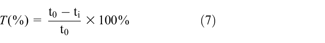
where t0 is the initial thickness of the sample, ti is the thickness of the measuring point of the forming hole.
Fifteen points were selected for the measurement. Owing to the vacuole collapse impact, the material flow was difficult under the rigid contact constraint of the round corners of the micro-die; thus, the minimum thickness is 70.4 μm at the rounded corners of the micro-die. The restriction on the part from the rounded corners of the micro-die to the center of the cavity is lacking under the action of inertia effect, it tends to increase and then decrease. Figure 15 illustrates the thickness distribution of the micro-hole section.

Cross-section thickness distribution of the formed.
Figure 16 shows the variation of thickness thinning rate of array micro-holes in the bubble impact zone of the 304 stainless steel foil under pressure of 20 MPa, target distance of 120 mm, and impact time of 5 min. The thickness thinning rates of the array micro-formed parts in the impact zone of cavitation bubbles collapse are between 2% and 13.5%, and the variation trend of the thickness thinning rate between the micro-formed holes at different positions is the same. However, the overall thickness thinning rate of array micro-holes with radius r = 13.6 mm is larger, and the maximum value is 13.5% at the rounded corner of micro mold. The overall thickness thinning rate of array micro-holes on radius r = 10.2 mm is smaller, but its maximum value also appears at the corner of micro mold, which is 10.75%. In addition, the thickness thinning rates of all the array micro-holes are generally between 2% and 10% except at the fillet, which indicates that the thickness distribution of the samples impacted by cavitating water jet is good.

Cross-section thickness distribution of the formed part.
Compared to the 50% thickness thinning rate achieved by Gao 23 and Li 24 using laser shock micro-forming, the non-uniformity of cavitation water jet micro-formed parts has been significantly reduced. The main reason is that cavitation impact acts as a flexible water hammer impact, with the random impact pressure working on the material surface more uniformly distributed. Additionally, 304 stainless steel has good mechanical strength and is not easily thinned by stretching. Furthermore, this indicates that the uniform distribution of bubble clusters on the foil surface is beneficial for obtaining relatively consistent deformation.
Conclusion
A novel method for the micro-forming of metallic plastic array is researched in this paper, and the feasibility of the technique is verified and an ideal array of 304 stainless steel micro-holes are obtained. The results are as follows:
(1) The impact zone of vacuole collapse is verified as the best micro-forming region of the array. The forming effect is the best when the impact time of array micro-holes is 5 min at the position of radius r = 13.6 mm and the target distance is 120 mm. Its mean deformation depth was up to 166.4 μm, and the variance was only 5.9 μm.
(2) When the shock waves generated by cavitation collapse are applied to the surface of the foil, the surface roughness of the array micro-holes is increased, and the maximum roughness Ra = 1.54 μm. The thickness reduction rates of array micro-forming parts are generally between 2% and 10%. The maximum thinning rate is located at the rounded corner of the micro-die only 13.5% with the thickness of the section distributed evenly.
(3) The method in this paper has the characteristics of low cost, green, high efficiency, strong applicability, and no need for punching. It can realize array micro-forming and automation, mass production. It is a beneficial exploration and attempt for micro-forming of new foil arrays, and has high research value and good application prospects.
(4) This study is a beneficial exploration and attempt for micro-forming of novel foil arrays and has high research value and good application prospects. The latter will also carry out the study of the material microstructure changes, grain size, and phase change organization of the rule of change to further explain the processing mechanism of cavitation water jet array micro forming.
Footnotes
Appendix
Handling Editor: Sharmili Pandian
Declaration of conflicting interests
The author(s) declared no potential conflicts of interest with respect to the research, authorship, and/or publication of this article.
Funding
The author(s) disclosed receipt of the following financial support for the research, authorship, and/or publication of this article: This study was funded by the financial support of the Six Talent Peak Selection and Training Program of Jiangsu (XNYQC-002), Jiangsu University Senior Talent Start-up Funds (16JDG038), Equipment Pre-Research Field Fund Project (80923010201), the opening foundation of the State Key Laboratory of Space Medicine Fundamentals and Application, Chinese Astronaut Research and Training Center (SMFA20K07), and National Natural Science Foundation of China (52105259).