
Abstract
The structural parameters of the first stage impeller have an important influence on the performance of multistage pumps, and the purpose of our study is to find the most significant factors affecting the performance of double-casing multistage pumps, and then to carry out a comprehensive optimization of the hydraulic performance and cavitation performance. With the Plackett-Burman design method, we made a notability analysis on impeller parameters, and the three control variables that are most sensitive to performance of multistage pumps were found. Based on the response surface method, we carried out the central composite design experiments for the sensitive control variables, and established the multiple regression model between the sensitive parameters and the performance parameters. By solving the regression model, the most significant parameters affecting the performance were obtained: impeller outlet angle, outlet diameter and wrap angle. After analyzing the interaction between impeller parameters, it was found that the optimal hydraulic performance and the optimal NPSHr will constrain each other, and the optimal parameter combination with the lowest NPSHr and the hydraulic performance not lower than that of original model is impeller outlet diameter, D21 = 292 mm, the impeller outlet angle, β21 = 19°, and the wrap angle, φ1 = 160°.
Keywords
Introduction
Considering the cavitation problem, the structural parameters of the first stage and secondary impellers of multistage pump are different, and the shape and structural design of first stage impeller determine the cavitation performance. In addition, influenced by the inlet conditions of suction chamber, channel shape of the first stage impeller is also very important to the multistage pump hydraulic performance.
At present, study on multistage pump mainly concentrated in the influence of impeller parameters on pump hydraulic and cavitation performance. Huang and Guan 1 simulated the whole process of bubble formation, developing and condensation in the first stage impeller. Chen et al. 2 improved the multistage pump NPSHr by increasing the inlet diameter and outlet width of first stage impeller. During the simulation of two-phase flow of the first stage impeller and guide vane of centrifugal pump, Guan 3 found that the change in bubble initial position on the back of blade has a certain influence on the spread and the degree of cavitation. Roche-Carrier et al. 4 studied the effect of first stage guide vane inlet diameter, blade number and clearance size on pump head and cavitation performance of a high-capacity multistage pump. Cong et al. 5 studied the effect of clearance size on the flow field and performance of multi-stage pumps. Nagahara and Inoue 6 studied the impact of blade profile of 4-stage centrifugal pump on efficiency and cavitation performance with experimental and numerical methods. Yi et al. 7 studied the impact of blades numbers in the first stage impeller of a multistage pump on flow characteristics inside the pump channel, and found that while the blades number is 4 and 8, the flow in the impeller was disordered. When the blades number is 5, 6, and 7, the impeller inner flow was smooth, and the head and efficiency were higher. Jiang et al. 8 found that the pressure on the back of the first stage impeller blades inlet was the lowest, and cavitation was easy to occur. Adding guide vanes could well reduce the flow rate and remove the rotation components of flowing medium. Mu Jiangang, Wan et al., and Wang et al.9–11 studied the impact of blade wrap angle on the cavitation performance of centrifugal pump and found that there exists an optimum for wrap angle, which can make the cavitation performance best at rated flow rate. Increasing the wrap angle will decrease the inlet cavity volume fraction and improve the flow distribution inside centrifugal pump to some extent. At the same time, it was found that the larger the wrap angle, the better the cavitation corrosion resistance of high specific speed centrifugal pump. Kang, Wang et al.12–15 analyzed the impact of impeller inlet diameter, blade inlet angle, outlet width, wrap angle, attack angle and equivalent diffusion angle of pressure chamber on the cavitation performance by numerical calculation. It was found that the impeller outlet width has little influence on cavitation performance for centrifugal pump, and there is an optimal value for both impeller inlet diameter and inlet angle, which makes the pump cavitation performance reach the best. Kim et al. 16 analyzed the steady flow and transient flow characteristics of the fluid in a 3-stage centrifugal pump under different working conditions, and the research results showed that the transient numerical results were more consistent with the test results. Lee et al. 17 studied the impact of curvature radius of the impeller blades on secondary circulation flow inside the impeller flow channel, and found that reducing the curvature radius can smooth the flow line and reduce the circulation amount of the secondary flow. Yan et al. 18 conducted the full flow channel numerical simulation of the gas-liquid two-phase multistage pump, and analyzed the distribution law of liquid velocity, gas phase, and pressure of the first two stage impellers under different relative blade heights. Then they found that the Euler non-uniform two-phase flow model and discrete particle Population Balance Model (PBM) can capture the gas-liquid flow state inside channel effectively. Suh et al. 19 studied the impact of variable drive systems on performance, pressure, and velocity of multistage pump through experiments and numerical simulation. Zhai et al. 20 studied the relation between the inlet pre-rotation of a 2-stage impeller and head of a multistage pump, and optimized the pump performance by setting a separator in the volute. On the other hand, many scholars have optimized the impeller parameters of centrifugal pumps by optimization algorithms and statistical methods. 21 Ding 22 optimized the guide vane of a multistage pump with genetic algorithm, and the optimized pump head was increased by 7 m. Lin et al. 23 proposed an optimization method based on particle swarm optimization and least squares support vector regression surrogate model. And they have achieved optimization of pump head and efficiency. Li et al. 24 achieved the recognition of cavitation based on the Complete Ensemble Empirical Mode Decomposition with Adaptive Noise and particle swarm optimization support vector machine algorithm. Based on the combination of experimental design method and a radial basis function, Lu et al. 25 established an optimization platform with the goal of improving the hydraulic performance of axial flow pumps. In addition, the response surface method is a statistical method suitable for optimizing hydraulic machinery. 26 Dai et al. 27 screened the parameters with the most significant effect on noise based on sensitivity analysis, and analyzed the interaction between pump efficiency and parameters. Wang et al. 28 achieved the vane optimization for fire pumps based on experimental design and response surface method. Duccio et al. 29 optimized a centrifugal compressor impeller by combining the experimental method, response surface method and multi-objective optimization algorithm.
The above research shows that the shape parameters of the first stage impeller blade have an important effect on hydraulic performance and cavitation performance of multistage pumps, but the interaction between the structural parameters of the first stage impeller on the pump comprehensive performance is rarely reported. In addition, the optimization method combining response surface methodology with CFD technology is feasible.
This paper takes the P101A multistage centrifugal pump, a methyl ethyl ketone raw material pump from a certain company in Lanzhou as the research object. After considering the structural parameters of first stage impeller in a comprehensive manner, combining experimental analysis, response surface methodology and CFD techniques to analyze the primary and secondary factors affecting the NPSHr, efficiency and head. Then the multiple regression model between the multistage pump performance and the control variables is obtained. And the parameters combination of the first stage impeller satisfying the comprehensive performance is found by analyzing the interaction between the different control variables, which provides a foundation for optimizing the first stage impeller and the research of cavitation inhibition of the double-casing multistage pump.
Three-dimensional model and numerical calculation methods
Research object and parameters
The P101A pump is an 11-stage multistage pump with the main parameters under design conditions are as follows: flow rate Q = 128 m3/h, stage number = 11, single-stage head H = 106 m, rotation speed n=2986r/min. The Figure 1 shows structure of the model, and the Table 1 shows the geometric parameters of main overflow components.
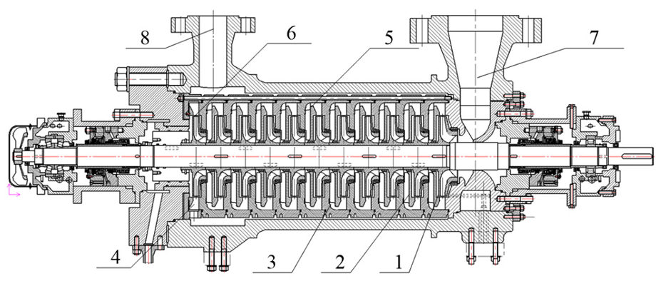
Structure diagram of the multistage pump: 1- First stage impeller, 2- Secondary impeller, 3- Guide vane, 4- Last stage guide vane, 5- Middle section of pump case, 6- Middle section of the last stage, 7- Suction chamber, 8- Pressurized water chamber.
Main parameters of the overflow components of the multistage pump.

Calculating domain and meshing
The calculational domain of multistage pump mainly include the suction chamber, first stage impeller, secondary impeller, guide vane, last stage guide vane, pressurized water chamber. The three-dimensional modeling of multi-stage pump is carried out by software Pro/E 5.0, and the calculation domain is shown in Figure 2.

Calculating domain of the multistage pump: 1- Suction chamber, 2- Front shroud of the first stage impeller, 3- First stage impeller, 4- Rear shroud of the first stage impeller, 5- First stage guide vane, 6- Front shroud of the secondary impeller, 7- Secondary impeller, 8- Rear shroud of the secondary impeller, 9- Last stage guide vane, 10- Pressurized water chamber, 11- Balance drum, 12-Orifice plate, 13-Balance pipe.
The multistage pump calculation domain was divided into hexahedral structured grid by ICEM CFD 16.0. By densifying the grid in the near wall region, the first layer of grid in the near wall region with a dimensionless height of y+ less than 5 was obtained. Figure 3 shows the grid of main overflow components. The pump efficiency and axial force were chosen as the evaluation criterion. As shown in Figure 4, when the grid number was greater than 48.62 million, the variation of efficiency was less than 0.023%, and the variation of axial force was less than 0.35%. Therefore, the grid number of 48.62 million was used for numerical calculation.

Grid diagram of main overflow components: (a) First stage impeller and guide vane and (b) Secondary impeller and last stage guide vane.

Grid independence verification.
Numerical method
In this paper, commercial software ANSYS CFX 18.0 was used to calculate the multistage pump hydraulic performance and cavitation flow field. The SST
Experimental verification of numerical method
The main function of the experimental pump is to transport the feedstock into the reactor for the redox reaction, and the experimental system is shown in Figure 5. The motor of the experimental pump is the AMD400L2RBABM motor, which can satisfy the design velocity of 2986 rpm for pump operation. The pressure at pump inlet and outlet is measured by 7MF403 pressure transducer (error ± 0.075%); AE215 electromagnetic flow meter (error ± 0.5%) was installed at the pump outlet to measure the flow rate; During the measurement process of shaft power, the CTK-38 opening current transformer from Electrolux and the DTS634 three item voltage transformer from Chint Group were used to measure the current and voltage, and finally the shaft power was obtained by matrixing. In order to measure the pressure and flow rate in the balance tube, a MH6150 orifice meter (level 0.5) was installed at the axial position of the balance tube 153 mm away from the pump inlet, and a YB-150 pressure meter (level 0.4) was installed at the axial position of the balance tube 239 mm away from the pump inlet to measure the pressure.

Multistage pump test device diagram.
It can be seen in Figure 6. that the numerical calculation results are almost consistent with the experimental results. But the experimental values were always lower than the computation values, with a maximum error of 4.17% for head and 2.81% for efficiency. The reason for error is that the numerical simulation did not consider the energy losses caused by the friction between mechanical seals and bearings. To verify the accuracy of numerical simulation in predicting the pressure and flow inside the pump, this study measured the pressure and flow rate inside the balance tube and then compared them with the computation results. Compared with the experimental verification of the balance tube flow rate, the predicted results of CFD are relatively larger. The maximum error of flow rate is 4.49%, and the maximum error of pressure is 2.5% under the design flow rate, which is within the permissible range. This indicates that the numerical method chosen in this study can accurately predict the internal and external performance of the multistage pump, and can also provide reliable assurance for this study.
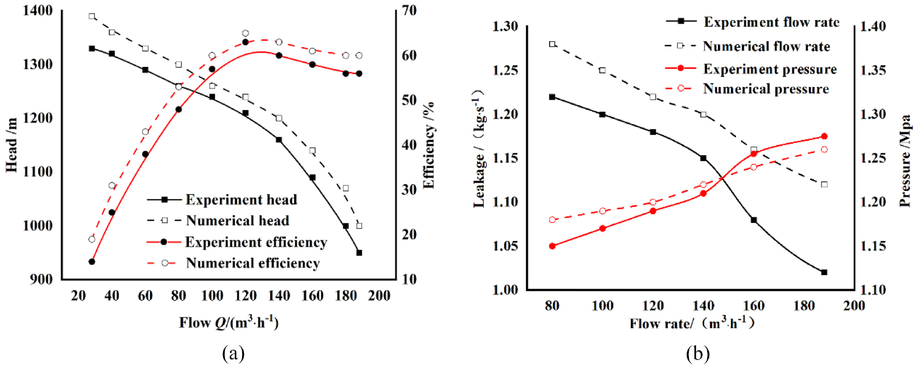
Comparison curve of numerical computation and experimental results: (a) Performance curve of the multistage pump and (b) Pressure and flow rate curve of balance tube.
Experimental design
Variable selection
The geometric parameters of first stage impeller of the multistage pump are taken as the research factors of PB design. And set high and low level for each factor. In this study, the control variables are impeller inlet diameter D11, blade number Z1, impeller wrap angle
The design software Minitable16 was used for experimental design and analysis. In addition to the above six factors, the virtual factors X1, X2, X3, X4, and X5 were added as error references. Table 2 shows the experimental design matrix. The calculation results of the corresponding pump head H, efficiency
Plackeet-Burman experimental design.

Results of Plackeet-Burman experimental design.

According to the experiment results, the least square method in regression analysis was used to estimate the regression coefficients, and conduct the significance tests on regression equation and regression coefficients. As shown in Table 4, T-value means the significance of the corresponding p-value calculated in combination with the degree of freedom. The p-value indicates the possibility that each factor has no effect on performance and NPSHr. That is, the smaller the value, the more significant the effect on performance and NPSHr. Using the Analytic Hierarchy Process (AHP) to determine the weight of each indicator, that is, establish the judgment matrix of six factors level based on the p value, and then calculate the normalized weight vector of single level factor, and the proportion of weight vector values for each level factor is the corresponding weight value of the level.
Significance analysis of influencing factors of performance and NPSHr.
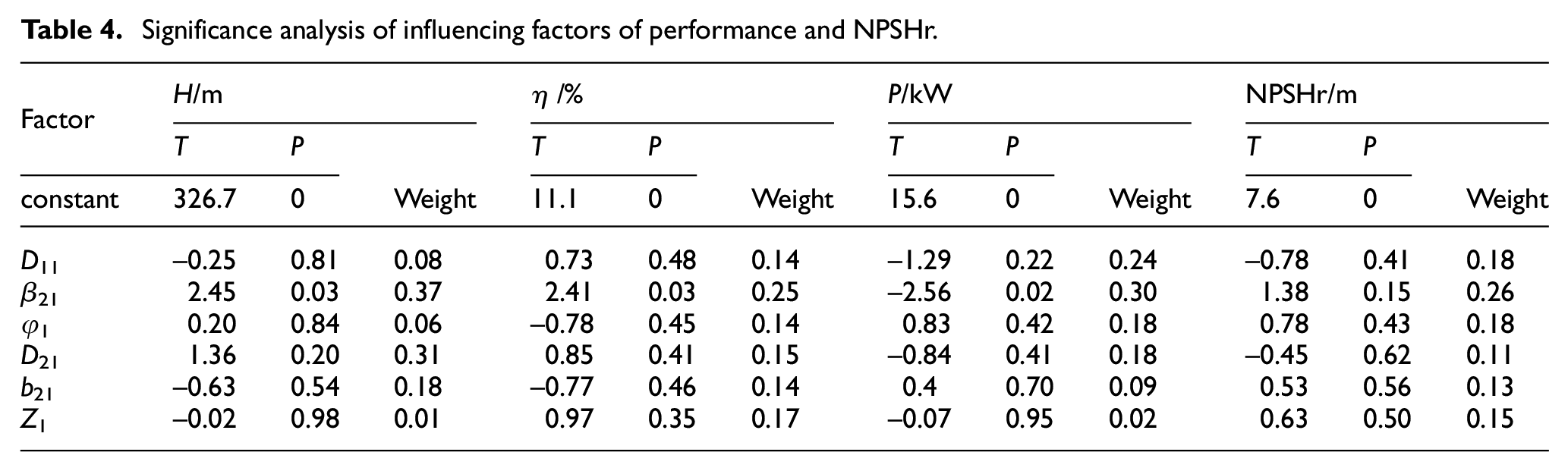
From Table 4, when the head index is investigated, the three most significant influencing factors are the impeller outlet angle β21, outlet diameter D21, and blade outlet width b21, which account for 37%, 31%, and 18%, respectively. When the efficiency index is investigated, the three most significant influencing factors are the impeller outlet angle β21, number of blades Z1 and wrap angle D21, which account for 25%, 17%, and 15%, respectively. When the shaft power index is investigated, the three most significant influencing factors are the impeller outlet angle β21, impeller inlet diameter D11 and impeller outlet diameter D21, which account for 30%, 24%, and 18%, respectively. When the NPSHr index is investigated, the most significant factors are the impeller outlet angle
To further calculate the weight index accurately, the game theory based on comprehensive weighting method
30
was used to fuse the influencing factor weights by using a simple correlation function. Through the combination weighting evaluation method of the game theory, the weights of pump head H, shaft power P, efficiency and NPSHr are assigned respectively, and four index weight sets

Aggregation model of the game theory was used to obtain
Response surface solution design
By the design-Expert software, the Central Composite Design method was selected to conduct the test design on the three significant factors: outlet angle
Level coding of response surface centered composite design factors.

Test scheme and results of first stage impeller.

Text result
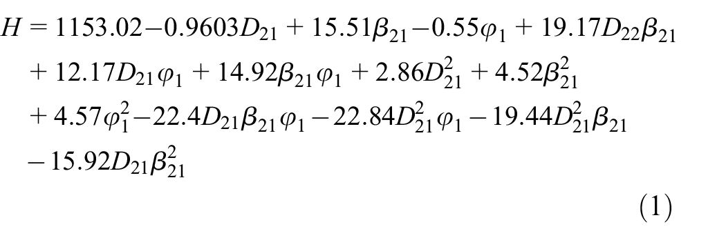
The establishment of the response surface model is performed with third-order polynomials. The quadratic term of each factor is taken and the first-order interaction is considered to obtain the regression equations of each factor of the first stage impeller, which are expressed as below:
Head regression equation:
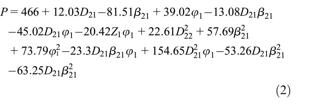
Shaft power regression equation:
Efficiency regression equation:

NPSHr regression equation:

To ensure the adaptability and correctness of the three-order polynomial regression equation obtained by fitting, it is necessary to conduct the significance test on the regression equation, which is usually tested by the difference analysis method and correlation coefficient method. While the correlation analysis method is mainly to test linear relationship of multiple linear regression. Therefore, the multiple correlation coefficient R2 and adjusted coefficient of determination
Analysis result of significance for regression equation.

Results analysis
Interaction between the first stage impeller parameters
The interactions between the impeller parameters of the influence function at the level of control variable 0 is shown in Figures 7 to 10. The parameters are the interactions between the impeller outlet diameter D21, outlet angle

Effect of interaction between first stage impeller parameters on head: (a) blade outlet angle and outlet diameter (b) blade outlet diameter and wrap angle and (c) blade outlet angle and wrap angle.

Effect of interaction between first stage impeller parameters on shaft power: (a) blade outlet angle and outlet diameter (b) outlet diameter and blade wrap angle and (c) outlet setting angle and blade wrap angle.

Effect of interaction between first stage impeller parameters on efficiency: (a) blade outlet angle and outlet diameter (b) outlet diameter and blade wrap angle and (c) blade outlet angle and wrap angle.

Interaction between first stage impeller parameters affecting NPSHr: (a) blade outlet angle and outlet diameter (b) outlet diameter and wrap angle and (c) blade outlet angle and wrap angle.
It can be seen from Figure 7(a) that the variation of impeller outlet angle and the impeller outlet diameter causes a large change in pump head. Larger impeller outlet angle and outlet diameter can improve the pump head, and the head curvature is the smallest while the impeller outlet angle and outlet diameter are near the 0 level. The combination of these two factors has a higher impact on pump head when the blade wrap angle is low. This is because when the blade wrap angle is small, the circumferential distance of the fluid passing through the blade decreases, and the change in impeller outlet diameter has a greater impact on the pump head. While the change in impeller outlet angle will affect the circumferential velocity of the velocity triangle, this affecting the energy exchange of the fluid. Therefore, the above combination has a more significant impact on the head when the blade wrap angle is small. Change of contours density indicates that interaction between the impeller outlet angle and outlet diameter is not obvious. As can be seen from Figure 7(b), as the impeller outlet diameter increases, pump head reduces first and then increases. The head decreases gradually with the reduction of wrap angle. The larger wrap angle and larger impeller outlet diameter can increase the pump head. The change of contours indicates that the interaction between blade wrap angle and impeller outlet diameter is not significant. Figure 7(c) shows that the impeller outlet angle and blade wrap angle slopes are gentle, the pump head increases gradually as the increase of outlet angle and blade wrap angle. Larger wrap angle and larger outlet angle can increase the pump head. These contours present as ellipses with large curvature, which indicates that interaction between the outlet setting angle and wrap angle is obvious.
As shown in Figure 8(a), shaft power of pump model decreases gradually with the decrease of impeller outlet angle, while the shaft power increases first and then reduces as the increasing of impeller outlet diameter. Shaft power is small when the impeller outlet diameter is at a 0 level and outlet angle is at a high level. There is no oval shape in the density of contour line, which indicates that the outlet angle and outlet diameter have no remarkable effect on response to the target shaft power. As shown in Figure 8(b), impact of wrap angle and impeller outlet diameter on shaft power is relatively slow, the shaft power of the two factors is small at a 0 level. The variation of contours density along wrap angle is larger than that of outlet diameter, which expressing that impact of wrap angle on shaft power is bigger than that of outlet diameter. As shown in Figure 8(c), the low level of outlet angle can increase the shaft power. And the outlet angle and wrap angle were near 0 level, resulting in lower shaft power. The contours exhibit an ellipse of greater curvature indicates that the interaction between wrap angle and outlet angle is obvious.
As shown in Figure 9(a), the effect of impeller outlet angle and outlet diameter on pump efficiency is complicated. Efficiency of multistage pump increases gradually with the increase of outlet angle, and increases first and then decreases with increasing of outlet diameter. Pump efficiency is larger while outlet angle is at a higher level and outlet diameter is at a higher or lower level. When the impeller outlet diameter is at the 0 level, pump efficiency is higher when the outlet angle is at a low level. Those two factors which near the 0 level of wrap angle can increase pump efficiency. The variation of contours density on the axis of the impeller outlet angle is greater relative to outlet diameter axis, indicating that outlet setting angle has a huge impact on pump efficiency than outlet diameter. As shown in Figure 9(b), the surface slop of impeller outlet diameter and blade wrap angle is gentle, pump efficiency increases at first and then reduces with the increasing of blade wrap angle and impeller outlet diameter. Pump efficiency is higher near the 0 level of wrap angle and outlet diameter. The contours exhibit an ellipse of greater curvature, which indicates that the interaction between impeller blade wrap angle and outlet diameter is remarkable. As shown in Figure 9(c), impact of wrap angle and impeller outlet angle on pump efficiency shows a convex surface distribution. With the increasing of blade wrap angle and outlet diameter, variation of wrap angle and impeller outlet diameter is first increased and then decreased. The high efficiency area is near the high level of impeller outlet angle and the 0 level of wrap angle. The contours exhibit an ellipse of greater curvature, which indicates that interaction between wrap angle and outlet diameter is remarkable.
As can be seen from Figure 10(a), impact of impeller outlet angle and outlet diameter on NPSHr is complicated. At the low level of outlet angle, NPSHr decreases first and then increases with the increasing of outlet diameter. At the high level of impeller outlet angle, NPSHr increases first and then decreases with the increasing of outlet diameter. When impeller outlet diameter is at a high level or low level, the smaller the impeller outlet angle is, the bigger the NPSHr is. Pump NPSHr decreases with decrease of outlet angle while impeller outlet diameter is near the 0.85 level. The NPSHr of the two factors was small near the impeller wrap angle of the 0.85 level. The contours indicates that interaction between the impeller outlet angle and the outlet diameter on NPSHr is not significant. As shown in Figure 10(b), effect of impeller wrap angle and outlet diameter on NPSHr exhibits surface distribution with a huge curvature concave. The smaller the wrap angle is, the larger the NPSHr is. Pump NPSHr decreases first and then increases with the increasing of outlet diameter while the impeller wrap angle is at a lower level. If the level of blade wrap angle is relatively high, NPSHr shows the tendency of increasing first and then decreasing with the increasing of impeller outlet diameter. As the high level of blade wrap angle and low level of outlet diameter, the pump NPSHr is relatively small. The variation of contours density indicates that impeller outlet diameter and outlet angle are not conspicuous in interaction. As shown in Figure 10(c), the effect of impeller outlet angle and impeller wrap angle on NPSHr exhibits a concave distribution. The NPSHr showed a pattern of rapid decrease followed by slowly increase while the blade wrap angle is small. The NPSHr increases gradually as outlet angle increases. The NPSHr is small when both the blade wrap angle and the outlet angle are all at the low level. The contours exhibit an elliptical distribution with larger curvature, illustrating the obvious interaction between the blade wrap angle and impeller outlet angle.
The above analysis showed a larger impeller outlet angle and a larger outlet diameter can bring the optimization of pump head and efficiency. However, it will also increase the NPSHr of the multistage pump. This is because cavitation in multistage pump often occurs near the inlet on the back of vanes, and the increasing of impeller outlet angle and outlet diameter reduces the twist of vane, which leads to a change in velocity of flow at the impeller inlet. In order to get the optimal hydraulic performance of double-casing multistage pump, the following combinations can be used, a large impeller outlet angle, a large impeller outlet diameter, and a small blade wrap angle. To minimize the NPSHr of double casing multistage pump, each control code should be close to the 0 level, and it can be found that the variation of the first stage impeller parameters has some constraints on optimization of cavitation performance and optimization of multistage pumps’ hydraulic performance.
Cavitation performance and hydraulic performance optimization of multi-stage pump
The NPSHr is taken as the main index of the problem, and the secondary analysis index efficiency is taken as the constraint condition. The regression equations (2) and (3) of the first stage efficiency and the NPSHr are solved simultaneously under the constraint condition. And the 3 factors value that minimize the NPSHr under the condition that efficiency is not less than primitive value can be obtained. The parameters are D21=292 mm, β21 = 19°, φ1 = 160°. The blade profile before and after optimization are shown in Figure 11.

The blade profile of first stage impeller before and after optimization.
Comparison of cavitation performance before and after optimization
Figure 12. shows the pump NPSHr before and after optimization under the design condition. Compared with NPSHr before optimization, NPSHr after optimization decreases by 1.47 m, which is because with the optimization, the flow inside pump channel smoother. Then the inlet loss is reduced, and the NPSHr gradually decreases. The anti-cavitation of first stage impeller is enhances by degrees, which shows that cavitation performance is greatly affected by blade wrap angle.
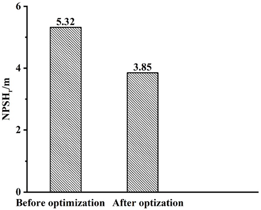
The NPSHr of the first stage impeller before and after optimization.
As shown in Figure 13, the vacuole volume variation of multistage centrifugal pump in one cycle before and after optimization when the NPSHr is 4.53 m. It can be seen that there is a partial vacuole distribution at the back of impeller inlet. The main cause of this phenomenon is that the static pressure and speed distribution in the back area are dominant, and the cavitation nucleus is generated by pressure reduction at the impeller inlet, and the cavitation nucleus shrinks and collapses in the high pressure area. With the increasing of flow rate, the vacuole volume increases by degrees. Under the same flow conditions, vacuole volume at the first stage impeller inlet is significantly reduced after optimization, which indicates that optimized multistage pumps have better anti-cavitation properties.
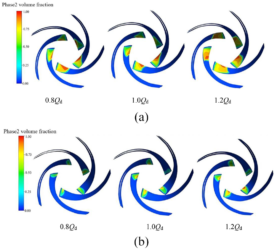
The distribution of vacuole volume fraction of the first stage impeller when NPSHr = 4.53 m before and after optimization.
Comparison of hydraulic performance before and after optimization
The pump axial force and hydraulic performance before and after optimization are shown in Figure 14. It can be seen that with the increase of the flow rate, the pump head decreases gradually, the shaft power increases gradually, and the efficiency increases first and then decreases. Under different working conditions, the hydraulic performance of the optimized pump is improved to a certain extent. Under the design working conditions, the efficiency is increased by 3.07% and the head is increased by 0.16%, which indicating that the multistage pump performance can be significantly increased by optimizing the blade profile with response surface method.

Comparison curve of hydraulic performance before and after optimization.
Comparison of flow field before and after optimization
Under the design flow rate, the streamline diagrams of the first stage impeller before and after optimization are shown in Figure 15. Before the optimization, there are several banded vortex strips in the flow channel, and the distribution of vortex strips spread from the inlet to outlet with a large range. After the optimization, the number of vortex bands is obviously decreased, and the flow of fluid particles in the channel become smoother. Optimization significantly reduces the hydraulic loss.
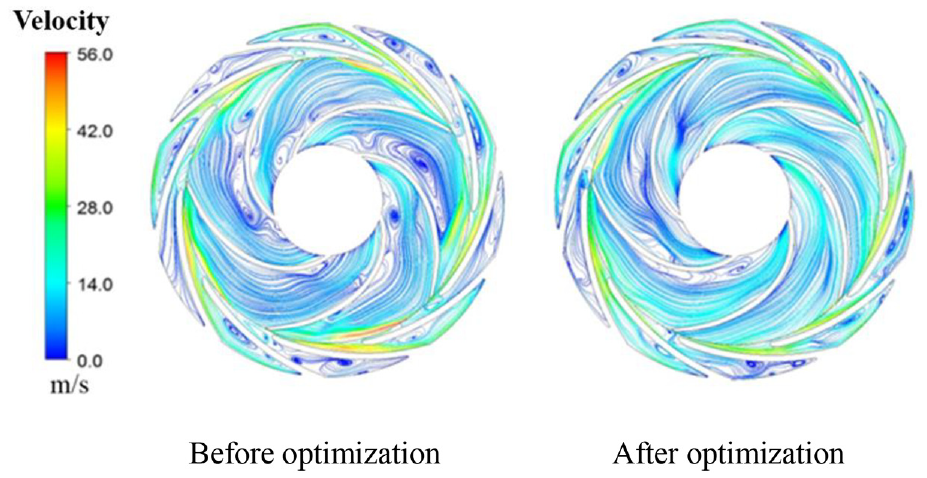
Streamline of the first stage impeller before and after parameter optimization.
To further characterize the unsteady flow characteristics inside the first stage impeller before and after optimization, the periodic changes of grid nodes pressure were calculated by statistical method through the pressure pulsation intensity coefficient
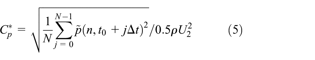
In the formula, n is the grid node; N is the sample number in the rotation period; t0 is the beginning time of rotation period; U2 is the impeller outlet peripheral speed.
Figure 16 shows the pressure pulsation intensity at the center section of first stage impeller under the design flow rate before and after optimization. The pressure pulsation intensity gradually increases from the impeller inlet to the outlet, and the high pulsation area is concentrated at the dynamic-static interface between the impeller outlet and the guide vane inlet. And the pulsation intensity inside impeller is generally greater than that of guide vane. Compared with result before optimization, pressure pulsation intensity inside flow channel of first stage impeller decreases after optimization, and pressure fluctuation at the first stage guide vane inlet increases.

Pressure fluctuation intensity of the first stage impeller before and after parameter optimization.
Conclusion
By combining the Plackett-Burman design method with the game theory method, we obtained the three most significant parameters affecting the hydraulic performance and cavitation performance of the double-casing multistage pump are: the first stage impeller outlet angle, the impeller outlet diameter and the blade wrap angle. The interaction between structural parameters of the first stage impeller has an important effect on the comprehensive performance of multistage pumps, and interactions between the factors have large differences. A large first stage impeller outlet angle and a large outlet diameter can improve the pump head and efficiency, but at the same time, it will increase the multistage pumps of the NPSHr. To achieve optimum hydraulic performance, the parameters combination should be a large impeller outlet angle, a large impeller outlet diameter, and a small blade wrap angle. To minimize the NPSHr, each control code is preferred to be close to the 0 level. This shows that the optimal hydraulic performance and the optimal NPSHr will constrain each other.
To achieve a comprehensive optimization of the hydraulic and cavitation performance, the interaction between the structural parameters should be considered. Based on the solution of multiple regression equations, a parameter combination of impeller outlet diameter D21=292 mm, outlet angle β21 = 19°, and wrap angle φ1 = 160° is obtained. With this parameter combination, the NPSHr can be minimized and the hydraulic performance is guaranteed not to be lower than the previous model. Optimized multistage pump hydraulic performance has significant improvement. Under the design condition, the pump efficiency increased by 3.07%, the volume of bubbles at the inlet of the first stage impeller is significantly reduced, the pump NPSHr reduced by 27.47%. The research results can provide theoretical guidance for improving the hydraulic performance and cavitation performance of double-casing multistage pumps.
Footnotes
Handling Editor: Aarthy Esakkiappan
Declaration of conflicting interests
The author(s) declared no potential conflicts of interest with respect to the research, authorship, and/or publication of this article.
Funding
The author(s) disclosed receipt of the following financial support for the research, authorship, and/or publication of this article: The study is supported by the Gansu Postdoctoral Science Foundation (Number: 23JRRA797).