
Abstract
In this article, performance analysis of a four-stage centrifugal pump is presented and discussed by means of numerical simulation and experimental test methods. Calculation domain in simulation was created based on a four-stage real pump model and meshed with the high density of structured grids according to the grid independence analysis. The numerical simulations under multi-conditions were performed based on standard k-e turbulence and standard wall function. Pump performance curves acquired by numerical simulation and the test are basically coincident; the total head, total power, and efficiency values are similar and changing trend is consistent under the different flow conditions. Flow in first stage is dramatically different compared with other stages. The results present that the four-stage simulation could reflect the real flow more precisely than the two-stage simulation, but also have higher requirements about the computer configuration. To balance the time consuming and numerical accuracy, two-stage simulation is a better choice to predict the pump performance. The results of this study provide the basis and reference for the further improvement of multistage centrifugal pump performance.
Introduction
Multistage centrifugal pumps, the core equipment for increasing the liquid pressure, have been widely used in the field irrigation, urban afforestation, and ground water supply. Multistage centrifugal pumps have more than two stages, up to tens or hundreds stages, which is more complicit than the single-stage centrifugal pumps for the hydraulic design due to the long shaft and high-reliability requirements. 1
Many researchers have focused on the performance improvement for multistage centrifugal pumps.2–4 Head, shaft power, and efficiency are the most important indicators in the pumps’ design; the most ideal design is all the indexes reach the optimal values at the same time, which is a huge challenge and time-consuming work. In the design of multistage centrifugal pump, experimental method has following defects: large investment, long period, limited analysis capacity for the whole flow field, and the subtle flow. Its advantage is that the hydraulic characteristic and performance are more close to the actual situation. Comparatively speaking, numerical simulation have less investment, short research period, and high precision, which is a kind of effective method to study fluid flow and predict the pump performance. Through the simulation methods, not only the optimal design model could be captured but also the design cost and time could be reduced, so this method attracts more and more engineering interests recently.
Many researches have been carried out in recent years about the computational fluid dynamics (CFD) study in pumps.5–10 Shukla et al. 5 carried out numerical experiment using CFD method, and the tested performance matched well with predictions within 3% at best efficiency point as regard to efficiency and head. Deigosha et al. 6 presented the experimental and numerical results at different flow conditions; the results show the ability of the model to simulate the complex three-dimensional development of cavitation in rotating machinery and the associated effects on the performance. Zhou et al. 7 compared the result between CFD and particle imaging velocimetry (PIV) and provided a good dataset for developing as well as evaluating the accuracy of various CFD models for capturing the complex flow field in compact return diffuser used with multistage pumps. However, due to the difficulties of better reproducing the complex geometry configuration of flow domain, most of these studies have been carried out with strong simplifications of the models, either in the geometry or in the flow characteristics. The calculation model selected only one or two stages to simulating the performance and flow field distribution. Since the flow field is more complex and the flow characteristics are different from signal-stage centrifugal pump, selecting the stages’ number is particularly important in the numerical simulation of multistage centrifugal pump. 11
In this article, in order to study the performance characteristics of the multistage centrifugal pump with variable operation state, a four-stage pump was investigated by test and numerical methods. Both experimental and numerical approaches were adopted to enhance the understanding of the complex flow characteristics that occur in a multistage centrifugal pump.
Numerical methods
Calculation model
A typical four-stage centrifugal pump was chosen as research model. Its main design parameters are summarized in Table 1. The impeller blades were designed as the cylindrical type, and the main geometric parameters of impeller and diffuser are shown in Table 2. To ensure the compact machining process and lower roughness, the impeller and diffuser are made by plastic material. Three-dimensional solid models of impeller and diffuser are shown in Figures 1 and 2.
Design parameters of research model.

Main parameters of impeller and diffuser.

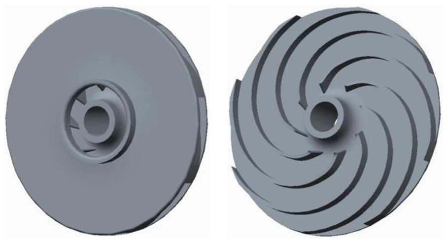
Solid model of impeller.

Solid model of diffuser.
Calculated domain
To ensure the accuracy and reliability of numerical simulation, four-stage whole flow fields were adopted to create the calculation domain. Generally speaking, impeller wear-ring causes volumetric leakage losses, pump cavity between the impeller and the diffuser causes friction losses of disks, both of them should be included in the calculation model. Creo3.0 software was used for the modeling of whole flow field of four-stage multistage centrifugal pump, which consists of eight components, namely, inlet section, inlet cover, wear-ring, impeller, pump cavity, diffuser, outlet cover, and outlet section. In order to improve the convergence precision and avoid backflow, inlet section and outlet section were extended. The final calculation domain was shown in Figure 3, each stages include wear-ring, impeller, pump cavity, and diffuser.

Calculation domains of four-stage centrifugal pump.
Numerical methods
Mesh generation and grid independence analysis
The whole mesh generation process was carried out in ANSYS-ICEM14.5 software. Inlet section, wear-ring, and outlet section, having simple structure, are meshed with structured grid. Impeller, diffuser, and pump cavity have complex structure, also have great influence on the internal flow field, so these parts were meshed with structured grid, too. The inlet cover and outlet cover have relatively complex geometry, but little influence on the internal flow field, so they were meshed with unstructured grid. Meshes on each parts of the whole calculated domain are shown in Figure 4.

Grids in fluid domains: (a) inlet section, (b) outlet section, (c) wear-ring, (d) pump cavity, (e) impeller, (f) diffuser, (g) inlet cover, and (h) outlet cover.
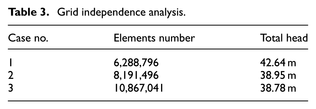
Grid independence analysis was carried out to choose appropriate mesh. Three cases with different grid numbers were simulated under the design flow (4.8 m3/h), and the predicted results of head are shown in Table 3. We could find that the case 1 has too coarse grid, leading to higher head compared with the other two cases. Comparing cases 2 and 3, the relative error is only 0.44%, which means case 2 has enough fine mesh to carry out the following simulation. The detailed grid and node number of case 2 are listed in Table 4, and the total mesh number is about 8.2 million. Meanwhile, in the mesh process, we ensure that 30 < y+ < 60 in the entire computational domain, which indicates that the near wall mesh nodes are located in log-law layer. 12
Grid independence analysis.
Final grid information.

Boundary conditions
After generating grid, the whole flow field is set to three-dimensional incompressible steady turbulent flow field in solver of ANSYS-CFX 14.5 using standard k-epsilon turbulence model. Setting impeller as rotating component, other sub-domains are set as stationary components. Interfaces contacting with the impeller were set to “Frozen Rotor”. Inlet of calculated domain is set as velocity inlet, and outlet is set as opening with relative static pressure according to design head of four-stage centrifugal pump. 13 Impeller and diffuser are molded by polyphenylene oxide (PPO) plastic material, which has high quality surface, so nonslip wall function was used, and the roughness of wall was set as 10 µm according to the real plastic surface. To ensure the accuracy and reliability of numerical simulation, high-order format discrete difference equation is adopted and the convergence precision is set as 10−5 in the solving process.
Performance test and comparison analysis
Performance test
Performance test of multistage centrifugal pump is performed at the laboratory of National Research Center of Pumps. The schematic arrangement of the test rig facility and test equipment are shown in Figure 5, which has the identification from the technology department of China. The test facilities and measure methods abide by the measurement requirements described in ISO 9906:1999 14 and also meet the requirements of Chinese standard GB/T 3216-2005. In the experiment, electricity measure method is used to measure the pump shaft power. Inlet pressure value is measured by vacuum gauge and outlet pressure value is measured by pressure gauge. Both vacuum gauge and pressure gauge have 0.3% measurement error. The volumetric flow rate of the pump was measured by a turbine flow meter, and its systematic measurement uncertainty is 0.2%.

Pump performance test rig.
Comparison between test and simulation
Four-stage multistage centrifugal pump was tested and simulated under different flow rates. The total head, power, and efficiency curves acquired by numerical simulation and performance test under different working conditions are compared and analyzed, as shown in Figure 6.
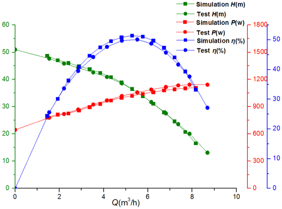
Comparison of predicted and measured performance curves.
As shown in Figure 6, the performance curves acquired by numerical simulation and the test have a very good agreement. The total head, total power, and efficiency values are similar and changing trend is consistent under different flow conditions. At the part-loading flow condition, the head of numerical simulation is higher and the power value is slightly higher than experimental values. With the increase in flow rate, total power is lower than experimental values; the efficiency of the numerical simulation is higher than the experimental values gradually. At the conditions of large flow rate, the total head value acquired by numerical simulation is close to the experimental values. With the increase in flow rate, the total head values are lower than experimental values, and the total power of the numerical simulation is always lower than experimental values. Therefore, the efficiency variation of the numerical simulation is faster than the test results at the large flow rate condition, the efficiency values of numerical simulation is higher than that of experiment first, and then it declines lower than the experiment value. Near the design flow rate, the total head values of numerical simulation are similar to the test results; the total power values and efficiency values are higher than the experimental values. At the design flow point 4.8 m3/h, four-stage total head and the efficiency acquired by numerical simulation are 38.95 m and 50.86%, respectively, comparing with the test values that total head is 38.66 m and the efficiency is 49.68%, the relative errors are 0.74% and 2.32%, respectively.
According to the above analysis, performance test results of multistage centrifugal pump are coincident with numerical simulation results; it proves the correctness and reliability of the numerical methods used in this article. Numerical simulation could become a convenient and effective method to predict pump performance, and it provides effective reference for the hydraulic optimization design.
Internal flow analysis and discussion
Performance comparison of different stages
For multistage centrifugal pump, each stage consists of impeller and diffuser, correspondingly having single-stage head and single-stage power. In order to analyze the difference of each stage, the predicted heads and powers of first stage, second stage, third stage, and fourth stage are compared, as shown in Figures 7 and 8.
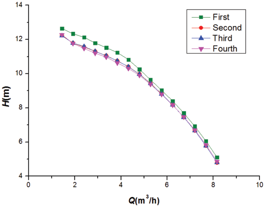
Head comparison of different stages.

Power comparison of different stages.
From above comparisons, we could find that the head and power of first stage is significantly higher than other stages. Especially, the maximum difference value occurs at the low flow rate condition. The reason is that flow at first-stage impeller inlet is irrotational associating with lower energy losses, so the single-stage head is higher than others. Heads and powers of second, third, and fourth stages are almost the same. Under the part-loading flow condition, the power of fourth stage is slightly higher than that of second and third stages, which may be caused by the inner severe turbulence flow or the computational error under strong off-design flow rates. At the design flow rate 4.8 m3/h, the head of first stage is 10.25 m and power is 252.80 W, increasing 3.5% and 1.6% at most compared with others.
To summarize, the flow state of first stage has larger difference with others, so predicting performance of multistage centrifugal pump cannot be simplified to a single-stage numerical simulation. But flow states of other stages are approximately same, multistage centrifugal pump can be simplified to a two-stage numerical simulation if we only consider predicting hydraulic performance, which could greatly reduce the calculated time consumption and cost.
Static pressure distribution
Static pressure distribution in pump meridian plane under 0.8 Q d, 1.0 Q d, and 1.2 Q d were compared in Figure 9. From the inlet to outlet section, kinetic energy is converted to pressure energy constantly, the general increasing trend of static pressure is presented. In the region of the impeller and the diffuser, static pressure gradient changes obviously due to impeller rotation.

Static pressure distribution at pump meridian plane: (a) 0.8 Q d, (b) 1.0 Q d, and (c) 1.2 Q d.
The difference in static pressure at outlet section is small under above three flow conditions, but the static pressure at inlet section is becoming lower and the difference value between inlet and outlet section is larger under the smaller flow, so head is becoming higher, that is coincident with changing trend of performance curves. 15 Pressure gradient variation of first-stage impeller is faster than others due to the irrotational flow at the inlet of the first-stage impeller.
Turbulent energy distribution
Turbulent kinetic energy value, reflecting the relationship of energy loss, is the important indicator to identify the turbulence evolution and variation. Turbulent energy distribution in pump meridian plane was compared under three different flow conditions, as shown in Figure 10.

Turbulent energy distribution in pump meridian plane: (a) 0.8 Q d, (b) 1.0 Q d, and (c) 1.2 Q d.
There are no obvious backflow in the entire flow passage, energy losses mainly occurs at the area between impeller and diffuser. It explains that the impeller and the diffuser are important hydraulic parts of multistage centrifugal pumps, and their structure variations have a great influence on the hydraulic performance. 16 Comparing these three flow conditions, turbulence kinetic energy of first-stage impeller is relatively larger compared with others; because the fluid has just entered the impeller, the blade power capability is weak and static pressure variation is unsteady. Consequently, the first-stage impeller of multistage centrifugal pump can be designed separately to further improve hydraulic performance. At 0.8 Q d, energy losses are concentrated in the interference area between impeller and diffuser compared with other two flow conditions.
Conclusion
In this study, numerical simulation and experimental test on a four-stage centrifugal pump was carried out. The pump performance and the internal flow field were discussed for each stage under different flow conditions. Through the comparisons and discussions about these results, conclusions could be drawn as follows:
There is a good agreement of the pump performance between the predicted simulation results and test results. Numerical results could provide effective reference for the hydraulic optimization design. The head and power of first stage are obviously higher than others.
Flow state of first stage has larger difference with others, so multistage centrifugal pump can be simplified to a two-stage numerical simulation if we only consider predicting hydraulic performance, which will greatly reduce the time consumption and cost of the numerical calculation.
Flow in first-stage impeller inlet is irrotational and obviously different compared with others, occurring large pressure gradient variation and turbulence kinetic energy. Pressure gradient and turbulent kinetic energy in rotor–stator interaction area of impeller and diffuser are larger, which has important influence on the hydraulic performance.
Footnotes
Academic Editor: Oronzio Manca
Declaration of conflicting interests
The author(s) declared no potential conflicts of interest with respect to the research, authorship, and/or publication of this article.
Funding
The author(s) disclosed receipt of the following financial support for the research, authorship, and/or publication of this article: This work was supported by the National Natural Science Foundation of China (Grant No. 51609106), Natural Science Foundation of Jiangsu Province (Grant No. BK20141302, BK20150508), Jiangsu Province Universities Natural Sciences Foundation (Grant No. 15KJB570001), National Science and Technology Small and Medium-sized Enterprise Technology Innovation Fund (Grant No. 14C26213201080), Key Research and Development Program of Jiangsu Province (Grant No. BE2015001-2, BE2015119), Policy Guidance Program in Jiangsu Province (Grant No. BY2015064-06) and the funding for the Construction of Dominant Disciplines in Colleges and Universities in Jiangsu (PAPD).