
Abstract
This work presents a study of wear on the clearance face of turning tools. This study will contribute to the development of improved machining precision and efficiency while extending tool life and also ensuring the surface quality produced, despite wear and edge deposition phenomena. A tool flank wear model is developed as a function of the cutting conditions, including the cutting speed, depth of cut, feed rate, and machining time. Factors influencing tool clearance face wear are determined through experimental testing. We also investigate the edge phenomenon reported on the tool cutting face by plotting a curve of the edge variation versus the machining time. Tool wear and built-up edge phenomena both affect the quality of the surface finish produced. Additionally, the edge phenomenon degrades the geometric quality of the tool and generates wear on the tool clearance face. Therefore, models are developed to aid in selection of appropriate cutting conditions that ensure the expected surface finish is realized while also providing control over tool wear. Overall, this method combines experimental and theoretical approaches to study and control turning tool wear with the aim of improving both machining quality and efficiency.
Introduction
Wear involves a complex set of phenomena that are difficult to interpret and causes an emission of debris with an associated loss of mass, dimension, and shape that is accompanied by physical and chemical transformations of the surfaces affected. 1 A large part of wear involves chemical reactions; chemically inert surface layers can sometimes prove to be more resistant to friction than hard layers, particularly in the presence of aggressive media. Wear is generally combated because of its negative effects but it also has favourable aspects for use in applications such as sharpening of tools or finishing of surfaces by grinding. 2
In the case of machining, these wear phenomena are essentially dependent on the cutting temperature. Two large groups of parameters can be observed during the cutting process: the first is represented by the properties of the machined material and the second comprises the cutting conditions (i.e., the cutting speed, feed, depth of cut, and lubrication properties). 3
Cutting tool wear occurs as a result of the very severe stresses that act on the cutting and clearance faces. These stresses are primarily mechanical in nature (e.g., permanent or cyclic stresses, the action of friction), which requires the cutting tool to have the qualities of hardness and tenacity. The intensity of these applied stresses is heightened by thermal effects, which accelerate the wear of the tool material and lead to its degradation. Moreover, these effects can produce physico-chemical reactions that mainly occur at the cutting face level (the tool-chip interface) and further aggravate the tool wear. 4 Wear of cutting tools affects both the quality of the parts produced and the cost of the machining process. When the wear reaches a certain critical value, the cutting forces, the process temperature and the vibrations all increase significantly and cause the stability of the cut to deteriorate. The machining operation must then be interrupted to replace the worn tool. 5 This tool replacement time and the low machining quality generated on the part increase costs and reduce productivity considerably. 6 At present, empirical approaches are used in industry to estimate tool life, but the empirical formulas obtained (wear laws) are based on numerous experimental tests that are often costly to perform and time-consuming. It is therefore necessary to develop a theoretical and experimental approach that can estimate the wear and the lifetimes of cutting tools while controlling the number of experimental tests required. The factors that influence wear are detailed in the diagram in Figure 1.

Diagram illustrating the parameters that affect tool wear.
Principle of tool wear
Built-up edge (BUE) is not a tool wear phenomenon (Figure 2). However, it has the same impact on machining as tool wear, i.e., a reduction in the cutting ability of the edge. Part of the material from the workpiece is deposited on the cutting edge, where it coats the cutting tool material and alters the geometry of its cutting edge. 7 The hardness of the cutting edge then becomes that of the workpiece material. This reduces the tool’s cutting efficiency.

Stages of wear formation and development of the built-up edge on the tool.
Therefore, the occurrence of the BUE causes dimensional inaccuracy and produces a poor surface finish on the machined part.
The BUE phenomenon occurs when the cutting speed is too low. This can occur with parts made from any material, most commonly with aluminium but also with steels, during turning and milling operations. 8 The material of the part at the cutting edge reaches a plastic (semi-solid) stage and then solidifies on the cutting edge. The strategy used to avoid the occurrence of BUE is to increase the cutting speed, causing the temperature at the cutting edge to increase to the point where the cut metal only solidifies after it leaves the cutting edge. 9 However, increasing the cutting speed in this manner can also generate an increase in wear.
Representation of built-up edge and flank wear
Using the data presented in Figure 3, the limits of both the wear zone and the added edge can be traced. The dashed line represents the main cutting edge of the tool and all the lines that lie above this dashed line represent the added edge as a function of time. 6 The BUE can then be evaluated by calculating the area between the two curves, as follows:

where Y(X) is the upper curve of the BUE.
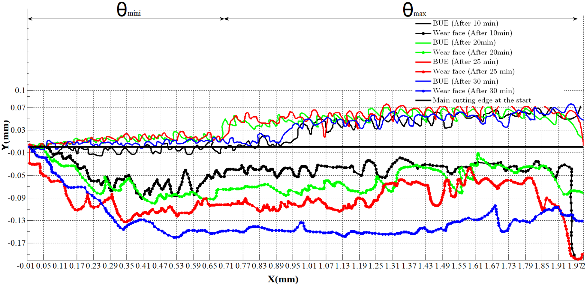
Curves of the wear edge and clearance face limits (cutting speed Vc = 52.5 m/min and the feed per turn fa= 0.2 mm/turn).
Model of main clearance face wear
The classical empirical wear law in draft form is given by equation (2). 10

where
This nonlinear equation can be transformed into a linear equation using the log function. We then obtain equation (3).

Equation (3) can be represented as a straight line as follows:

Identification of the parameters for equation (4) from the test results is conducted by applying the least squares method.
The matrix for this method is defined as follows:
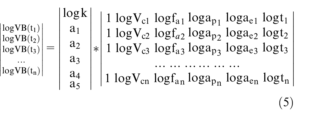
This matrix then follows the form of equation (3) and is represented as a line in the following form:

such that n=1, 2, …, represents the total test numbers.
The least squares method is then used to evaluate the parameters. A* is the optimal value of A that adjusts the model to fit the data most accurately and is evaluated using the least squares method, along with a tropic equation, and optimal values are found for the following parameters: k, a1, a2, a3, a4, and a5.
Experimental Method
Identification of the parameters requires implementation of the experimental tests that are detailed in the following paragraphs.
Tool and workpiece characteristics
The machined piece is composed of treated Inconel 718 with a hardness of 45 HRC. The diameter of the piece is 45 mm and its length is 80 mm (Figure 4a). The cutting tool is a round carbide insert with a nose radius of 4 mm and a height of 4 mm (Figure 4b). When this tool is mounted in the tool holder, the clearance angle is 6°. Flood cooling conditions are applied using a water-based emulsion coolant with oil content.
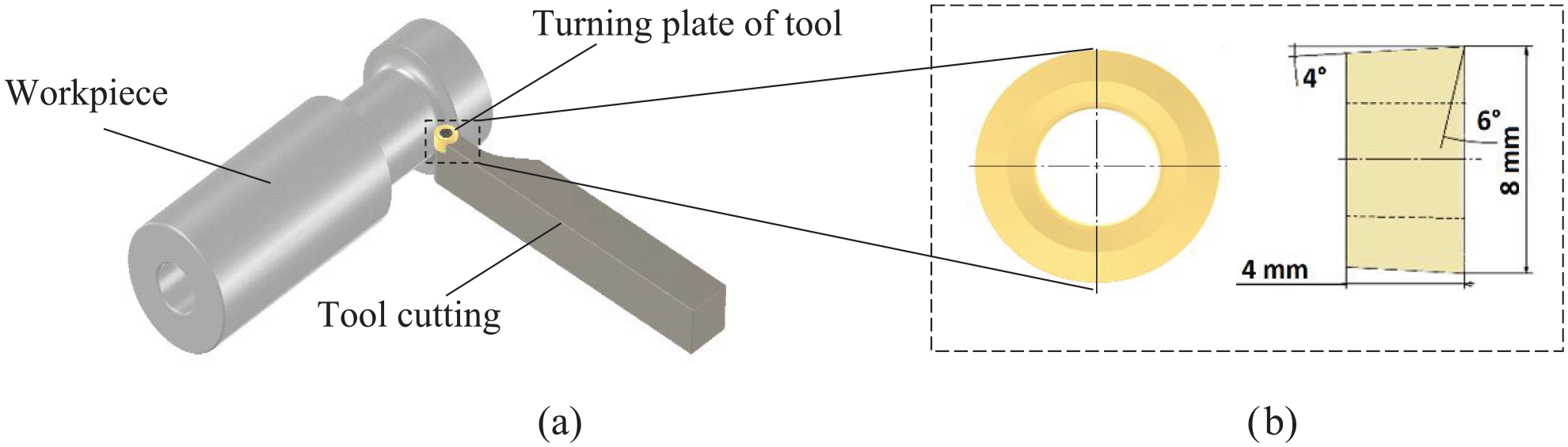
Illustrations of: (a) the machining test and (b) the geometry of the cutting tool used.
This study considers the turning operation required to form a deep groove with a depth of 4 mm and length of 20 mm at three cutting speeds,
Parameters taken from the experimental section.

t: machining time; VB: flank wear; Vc: cutting speed; fa: feed per turn; ap: depth of cut; ae: tool engagement.
Calculation of the maximum and minimum angles at the contact position of the tool and the workpiece
Based on the simulations illustrated in Figure 5, the maximum and minimum angles at the contact position of the cutting tool and the machined part in the reference plane can be determined using two cutting parameters, comprising the feed rate and the depth of cut

Simulations showing the tool wear after machining.

Maximum and minimum angular positions for contact between tool and workpiece.
The minimum angle defines the location of the beginning of the contact between the tool and the surface to be machined. This angle depends on

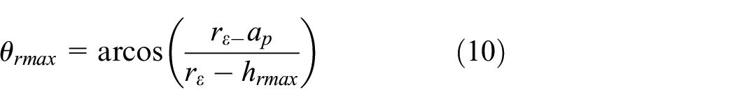
The maximum angle defines the position of the end of contact between the tool and the machined surface. This angle depends on

Finally, the maximum depth of path

Pictures of tool wear and BUE
After a machining trial was performed on a computer numerical control (CNC) machine that involved turning using a round insert tool, images of the clearance face of the tool were acquired at different times using a 42-pixel camera (see Figures 7, 8, 9, 10, 11, 12, 13, 14 and 15).

Tool flank wear: VB=0.091 mm, Vc=35 m/min, ap =0.5 mm and t=4.99 min.

Tool flank wear: VB=0.123 mm, Vc=35 m/min, ap =0.5 mm and t=10 min.

Tool flank wear: VB=0.292 mm, Vc=35 m/min, ap =0.5 mm and t=54 min.

Tool flank wear: VB=0.071 mm, Vc=52.5 m/min, ap=0.5 mm and t=3.01 min.

Tool flank wear: VB=0.294 mm, Vc=52.5 m/min, ap =5.5 mm and t=18.83 min.

Tool flank wear: VB=0.31 mm, Vc=52.5 m/min, ap =5 mm and t=15.09 min.

Tool flank wear: VB=0.066 mm, Vc=70 m/min, ap =0.5 mm and t=2.26 min.
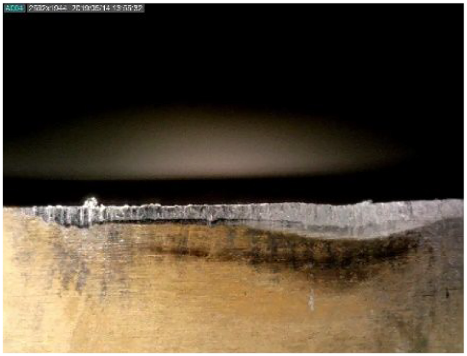
Tool flank wear: VB=0.077 mm, Vc=70 m/mm, ap =0.5 mm and t = 1.13 min.

Tool flank wear: VB=0.066 mm, Vc=35 m/min, ap =0.5 mm and t= 0.64 min.
The results for the experimental part of the wear are summarized as a function of the parameters VB, Vc, fa, ap and ae in Table 1.
The linear equation system in equation (4) is solved using the least squares method to calculate the unknown factors of the linear system and the results are given in Table 2, as follows:
Determined values of unknown linear system factors.

Tool wear model
Matlab calculation software was used to determine the following unknowns: a1, a2, a3, a4 and a5.
This allows us to give equation (9) in the following form:

Results and discussion
Through experimentation, we have identified the tool wear law for a coupled tool/machined part material system.
It should be remembered that the causes of wear and BUE can include:
• A cutting zone temperature that is too low;
• A negative cutting geometry;
• Machining of very sticky materials, including low carbon steel, stainless steels and Inconel 718.
Therefore, we can propose the following suggestions to reduce wear and BUE:
• Increase the cutting speed;
• Use tools that have a more positive rake angle and a sharper cutting edge;
• Increase the coolant supply dramatically.
Conclusion
This article presents the results of a study in which a draft wear law was identified for a turning operation on Inconel 718 samples. An experimental testing approach enabled identification of the parameters for the flank wear law. This experimental approach made it possible to model both the tool clearance face wear and the BUE, which varies as a function of time. Analysis of the experimental results made it possible to consider the following:
• The predominant wear phenomenon is abrasive wear. This phenomenon is manifested through the appearance of grooves (striations) on the flank face of the tool. Abrasive wear occurs as a result of particles being torn from the tool by the hard particles that constitute the machined material. At cutting speeds of 35, 52.5 and 70 m/min, the tool wear manifests through the appearance of a ridged and regular band on the relief surface and through formation of a crater on the attack surface. Over time, we noticed an increase in the wear VB, which leads to the collapse of the nose of the tool.
• Cutting speeds in excess of 70 m/min are not recommended because they lead to rapid tool wear. This causes the tool lifespans to be too short, which is not of industrial interest.
• Wear is one factor to be considered in machining because its evolution damages and degrades the surface condition of the machined parts.
• The determination of the mathematical models of wear and roughness is of significant industrial interest because these models enable determination of the optimal machining conditions and the development of charts for the process. During roughing operations, in which substantial amounts of material are removed from a workpiece to approach its final dimensions, formation of the BUE can indeed play a protective role for the tool. This occurs because the BUE acts as an additional layer on the cutting edge of the tool, which can reduce tool abrasion and extend the tool’s lifespan. Furthermore, BUE can help to stabilize the machining process by reducing vibrations and enhancing the tool’s thermal stability. However, during finishing operations, where tight tolerances and a high-quality surface finish are required, the presence of the BUE can become problematic.11–16 BUE can lead to the occurrence of undesirable marks on the machined surface, thus compromising the quality of the final part. Additionally, during finishing operations, light passes and reduced feeds are often used, and they may not be sufficient to break or remove the BUE effectively.
Footnotes
Appendix
Notations
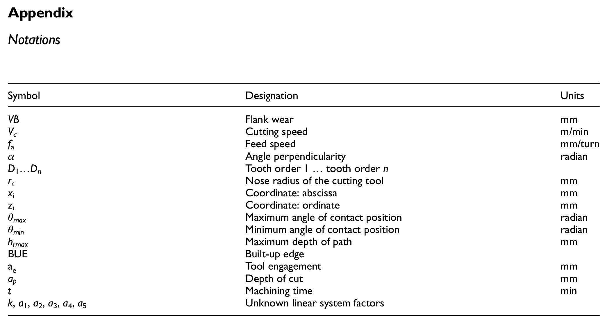
| Symbol | Designation | Units |
|---|---|---|
| VB | Flank wear | mm |
| Vc | Cutting speed | m/min |
| f a | Feed speed | mm/turn |
| α | Angle perpendicularity | radian |
| D 1…Dn | Tooth order 1 … tooth order n | |
| rε | Nose radius of the cutting tool | mm |
| x i | Coordinate: abscissa | mm |
| z i | Coordinate: ordinate | mm |
|
|
Maximum angle of contact position | radian |
|
|
Minimum angle of contact position | radian |
|
|
Maximum depth of path | mm |
| BUE | Built-up edge | |
|
|
Tool engagement | mm |
|
|
Depth of cut | mm |
| t | Machining time | min |
| k, a1, a2, a3, a4, a5 | Unknown linear system factors |
Acknowledgements
The authors would like to express their gratitude to Professor Benaoumeur Aour, Director of the Laboratory of Applied Biomechanics and Biomaterials at the National Polytechnic School of Oran (Algeria), for his support and his valuable contribution to this research. His efforts and expertise were instrumental in the completion of this work.
Handling Editor: Sharmili Pandian
Declaration of conflicting interests
The authors declared no potential conflicts of interest with respect to the research, authorship, and/or publication of this article.
Funding
The authors received no financial support for the research, authorship, and/or publication of this article.