
Abstract
Ultrasonically assisted turning is one of the modern machining processes developed in recent decades to facilitate machining of hard-to-cut materials which are widely used in different industries. Cutting tool wear is one of the main problems in machining of hard materials which has necessitated implementation of modern machining processes such as ultrasonically assisted turning. Due to vibro-impact conditions, cutting tool failure takes place when ultrasonically assisted turning is applied for hard and brittle materials. In fact, microchipping takes place in the tool nose after machining of short length, so sharp cutting edge fails at the early stages of cutting. Therefore, if the sharpness of cutting edge is removed before the machining, the fracture of cutting edge, caused by vibro-impact condition, will be eliminated. The aim of this research is to investigate the tungsten carbide tool flank wear in ultrasonically assisted turning of hardened alloy steel in comparison to the conventional turning. Therefore, a proper experimental ultrasonic vibration configuration was designed to apply the ultrasonic vibrations to the turning tool along cutting direction. Experiments were carried out for different cutting speeds below the critical speed in ultrasonically assisted turning. Application of the tool with modified specifications led to make an initial wear on tool flank, but finally a significant improvement of tool wear was observed.
Introduction
It is very difficult to machine hard materials such as hardened steels using conventional turning (CT). Hard turning is the machining process of parts with hardness more than 50 HRC. Hard turning differs from CT in different aspects such as the cutting tool geometry, chip formation mechanism, applied cutting conditions and especially tool wear. 1 Tool wear affects cutting tool life strongly and causes high tool temperatures. The wear of the cutting tool is made by the tool contact with the workpiece and chip. This interaction is also accompanied by high temperature of cutting edge which strongly affects the tool wear. If any change occurs in tool–workpiece interaction and contact condition, the tool wear is affected too.2,3 Tool wear has great influences on the tool life, tool substitution sequence that increases machine down time, surface finish and dimensional accuracy of machined workpiece. It also makes a substantial portion of the machining costs and eventually influences on process efficiency. Therefore, the researchers are interested in investigations about tool wear and several experimental and theoretical attempts have been made to explore different fields of this phenomenon, such as tool temperature, effects of cooling and lubrication, wear mechanisms, wear modeling and tool life predicting.4–12 In recent years, the methods that reduce tool wear and improve the tool life are the main purposes of several machining researches.12–15 Ultrasonically assisted machining (UAM) is an example of these methods which has shown good advantages in this field.16–18
UAM is an advanced method developed for machining of many modern materials, such as high-strength and heat resistant steels, titanium alloys, ceramics and other non-metallic materials which have low machinability by traditional machining methods. Ultrasonically assisted turning (UAT) is a new machining process in which the cutting tool vibrates with the constant ultrasonic frequency (frequency > 20 kHz) and small amplitude (amplitude: 10–40 µm) during machining process.19,20 The vibrations can be applied along the feed or cutting directions. UAT technique has brought outstanding advantages to machining of hard-to-cut materials.17,21 One of the main advantages of utilization of this technique is significant reduction in cutting forces which has been demonstrated by many researchers in experimental, analytical and computational investigations.22–24 In UAT, lower cutting forces can be achieved due to a considerable reduction of friction between the tool and workpiece and the separating of the tool from cutting zone.19,25 An improvement in surface finish and quality, lower effects on the machined surface hardness, promising effects on cutting stability and chip generation are the other advantages of the application of this technique.24–27
Cutting speed is a key factor on effectiveness of UAT process. Researches have shown UAT results in more efficiency at lower values of cutting speed.23,28 In UAT, cutting speed should be less than certain limit in which interrupted cutting takes place. This limit is considered as the critical speed, VCR = 2πaf, where a and f are the vibration amplitude and the vibration frequency, respectively. On the other hand, for cutting speeds close or beyond the critical values, UAT mechanism seems similar to conventional machining process. It is demonstrated that cutting speeds close to critical value bring more contact and interaction between tool and workpiece; hence, the ultrasonic vibrations would not be efficient in such conditions. 19
As mentioned above, one of the main purposes of development of machining processes is improvement of cutting tool wear and tool life properties. This aspect of UAT has reported by promising experimental investigations.16,17 Reduction of tool wear in UAT can be expressed by some consecutive events. Application of ultrasonic vibrations changes the nature of continuous contact of the tool and the workpiece to interrupted form. As a result, friction between the tool and workpiece reduces because of changing friction regime from semi-static to dynamic and average of cutting forces descends subsequently. The elimination of built-up edge (BUE), less heat generation and lower temperatures at tool–chip interaction are other specifications of this method which improve the cutting wear and tool life.17,19
Cutting process instability associated with large vibrations is the most commonly observed problem in low speed CT of hard materials which applies intensive fluctuating forces on the cutting tool, causes tool chipping, high tool wear rate and premature tool failure.29,30 In addition to intensive machine vibrations, loud machining noises, chatter and consequently high wear rate and low surface quality are other undesirable results of machining of hard materials using CT. Although the UAT can improve the stability of process, but in some cases a catastrophically failure has been observed in the cutting edge and nose of the tool during machining close or below the critical speed. 31 Also, another recent investigation revealed that the ultrasonic vibrations may have negative influence on the milling tool wear and showed that the ultrasonically assisted milling produces higher tool flank wear compared to the conventional milling. 32 This type of failure during UAM is caused by consecutive high impacts between the tool and workpiece. Therefore, the interrupted cutting characteristic of UAT can be problematic in some conditions by attention to cutting tool wear considerations. Interrupted cutting and vibro-impact condition in UAT may be added to the natural specifications of hard and brittle materials to make more critical machining condition. In fact, microchipping takes place in the tool nose after machining few meters, and the sharp cutting edge of the tool is broken at the early stages of cutting. Therefore, if the sharpness of cutting edge is removed before the machining, the fracture of cutting edge under the vibro-impact condition may be eliminated. Hence, the wear rate of modified tool in UAT may be less than CT and UAT with sharp edge tools. Considering these facts, the aim of this research is to investigate the tungsten carbide tool wear in UAT of hardened alloy steel in comparison to the CT. Therefore, a proper experimental ultrasonic vibration configuration was designed to apply the ultrasonic vibrations to the turning cutting tool along cutting direction. The experiments were conducted to investigate the tool flank wear with modified and ordinary edges in CT and UAT. The experiments were done for different cutting speeds below the critical speed in UAT in order to investigate the influence of cutting speed on the cutting process and its outputs. Slight modification of the tool edge achieves significant improvement in measurement of tool flank wear which will be explained in detail in the following sections.
Experimental procedures
Experimental UAT setup
A proper experimental UAT layout was designed to apply one-dimensional ultrasonic vibrations to the turning cutting tool in cutting direction. The designed configuration was consisted of an ultrasonic pulse generator, a 400 W transducer which transforms the electric pulses into low amplitude ultrasonic vibrations and a proper horn. Functional concept and constraints in designation of the ultrasonic horn are as follows:
Application of the cylindrical shape in order to achieve the best location for clamping system as well as utilization of conical shape to concentrate the vibrations.
Attention to the strength of the horn under cutting forces by considering sufficient values of the horn diameters.
The horn length was determined based on modal analysis using finite element method which has longitude vibration mode in 27 kHz. By some efforts, horn length was chosen in a manner that there were two points without displacement (node). The first zero-amplitude point (node) was located between two piezoelectrics. This positioning reduces stresses on piezoelectrics and increases their life time. The second zero-amplitude point (node) was placed in the middle of the horn (cylindrical section). So, this position was the best location for clamping of the horn to the dynamometer. Moreover, there was an anti-node at the horn tip where highest value of vibration amplitude was expected.
As shown in Figure 1(a), vibration node (a node in horn where its displacement is zero) has been placed on cylindrical section of the horn and used to clamp the dynamometer to the horn. Figure 1(b) shows the assembly of transducer, horn and tool. The experimental tool fixture design is shown in Figure 1(c). Nest of the insert on the horn end had a 5° side relief angle and 45° side cutting edge angle.
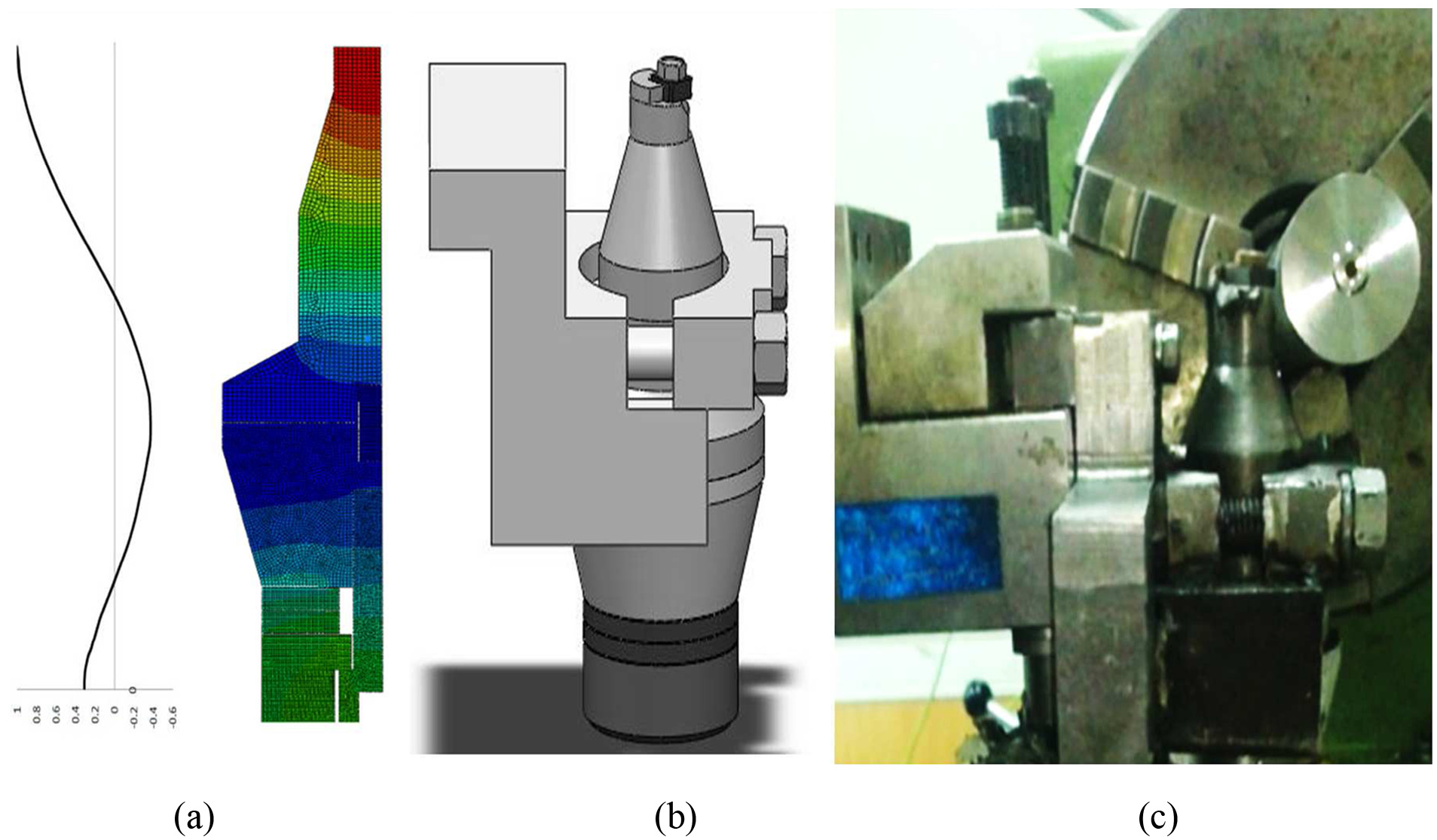
(a) Modal analysis of set of transducer and horn, (b) assembly of horn, tool and transducer and (c) experimental tool fixture view.
A PU-09 gap sensor, an AEC-5509 converter and an oscilloscope were used to measure the vibration amplitude of the tool tip. The measured value of vibration amplitude for 200 W ultrasonic power is 8 µm. The experiments were conducted using this configuration for both CT (while the ultrasonic power was off) and UAT.
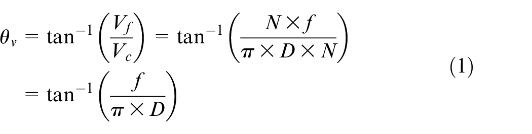
Direction of vibrations is an important subject that should be noted in design of configuration. In the UAT with 1D vibrations, if the vibrations are applied in direction perpendicular to the workpiece axis (Figure 2(a)), the tool tip encounters with the machined surface when the tool comes back at each vibrational motion and prevents separation of tool flank surface from workpiece. 33 If the vibration direction is exactly tangent to the real cutting direction, VC,real (Figure 2(b)), the tool flank is constantly in contact with the workpiece. The direction of real cutting speed θv can be derived from following relations
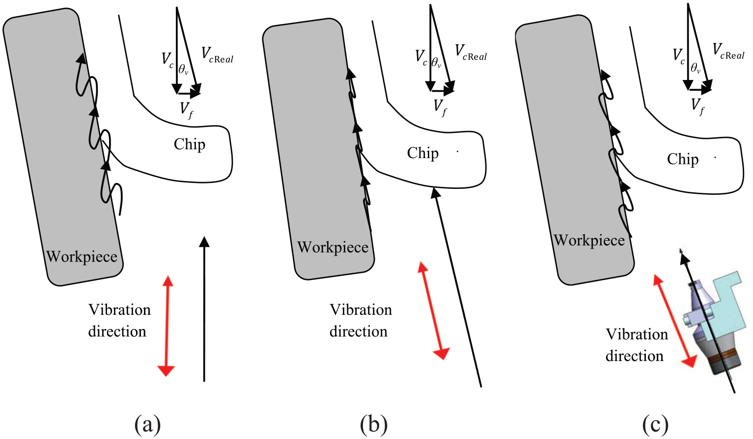
Implementation of ultrasonic vibrations in three directions: (a) vibration direction < θ V , (b) vibration direction = θ V , (c) vibration direction < θ V
where D is the workpiece diameter (mm), Vf is the feed rate (mm/min), f is the feed (mm/rev), VC is cutting speed (mm/min) and N is the spindle speed (r/min).
But if the vibration direction has an angle more than θv, the tool flank face is in contact with the workpiece only in the forward motion and separates from the workpiece in backward motion (Figure 2(c)). Therefore, it is essential to apply this change in vibration direction so that the set of transducer and horn should tilt more than θv in order to have efficient UAT process.
Material and tool
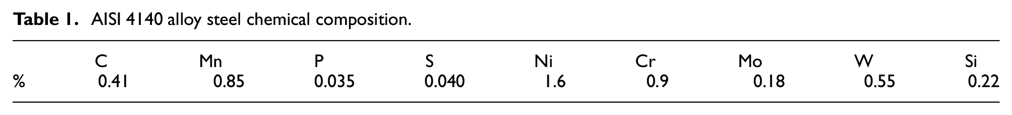
AISI 4140 hardened alloy steel rods (50 ± 2 HRC) with the dimensions of ϕ50 × 300 mm and the tungsten carbide inserts were employed in experiments. Inserts were coated with Chemical Vapor Deposition (CVD) (TiN) from Sandvik Coromant Company. Based on ISO insert nomenclature, the geometry of these inserts are SNMG 12 04 08. The chosen inserts have zero side rake angle and side relief angle, but the horn nest has the angle of −5°. So, real values of side rake angle, side relief angle and side cutting edge angle are −5°, 5° and 45°, respectively. The chemical composition of AISI 4140 steel is presented in Table 1.
AISI 4140 alloy steel chemical composition.
Design of experiments and measurements
The experiments were classified into four main phases: CT with ordinary tool, UAT with ordinary tool, CT with modified tool and UAT with modified tool. The vibration frequency, the amplitude of vibrations, feed rate and cutting depth were adjusted at 27 kHz, 8 µm, 0.14 mm/rev and 0.5 mm, respectively, based on the primary tests and the limitations of the equipment. The tool flank wear was measured after each 100 m cutting distance by a Dino-Lite AM-413ZT digital microscope. The experiments were carried out for different cutting speeds, such as 14, 18, 28, 34, 55 and 78 m/min below the critical speed (VCR = 2πaf = 2π ×27,000×8µm =81 m/min).
It should be noted that the modified tool was prepared by soft sandpaper to fillet the cutting edge slightly. This process was performed smoothly and perpendicular to the cutting edge of the tool, so a 0.03 mm initial wear was produced on tool flank face as shown in Figure 3. Modification procedure was controlled using the microscope. Two numbers of sandpapers were used. At first, the sandpaper by mesh number of 400 was used for roughing process in fillet preparation. Then, the sandpaper by mesh number of 1000 was applied to achieve the final profile and smooth surface.
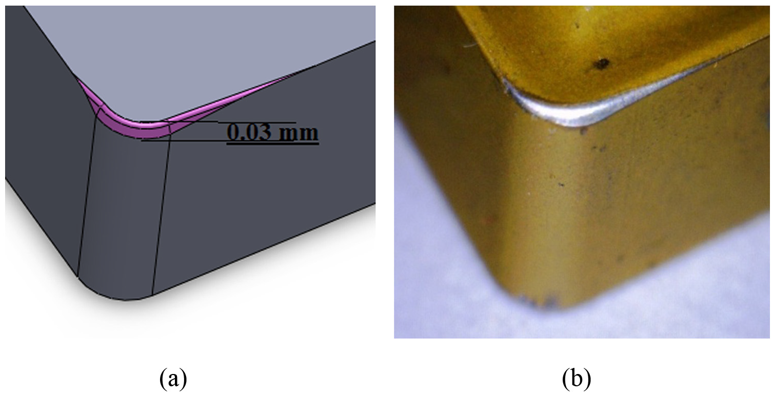
(a) Schematic and (b) actual view of the modified tool.
Cutting force measurements
Extensive theoretical researches, simulation and experimental results of the UAT method show that this method has a significant effect on the tool–workpiece contact ratio (TWCR) and this parameter directly effects on cutting forces. Previous researches have illustrated that the tool–workpiece contact and interaction forces between the tool and workpiece follows periodic changes during UAT.19,31 The maximum magnitude of cutting forces is achieved when the tool is in full contact with the chip, while cutting forces drop to zero levels when the tool disengages from the chip. 23 Cutting forces in most fractions of the process period are significantly less than those occurring in CT. Achieving lower cutting forces in UAT is related to a considerable reduction of friction between the tool and the workpiece and the interrupted cutting characteristics. 19 Results of cutting forces in some ordinary experiments were used to assure correct design and fabrication of UAT layout. A Kistler 9121 dynamometer was employed to measure the tangential cutting forces (main component of cutting forces which lies along machining direction). In order to compare CT and UAT processes more precisely, a 10 mm length of workpiece was machined by UAT, then the ultrasonic power was turned off and the same length of the workpiece was machined by CT. Significant reduction of cutting forces can be seen in Figure 4 as were indicated in previous researches.24,33,34 For instance, Figure 4(a) shows a 40% reduction in the UAT cutting force compared to the CT at 34 m/min cutting speed. As shown in Figure 4(b), it is clear that the most reduction in cutting force in UAT happens in low cutting speeds. The main cutting force has direct relation to the cutting speed. As mentioned, increasing of cutting speed results in higher values of TWCR, so influence of UAT on reduction of cutting forces descends. 22
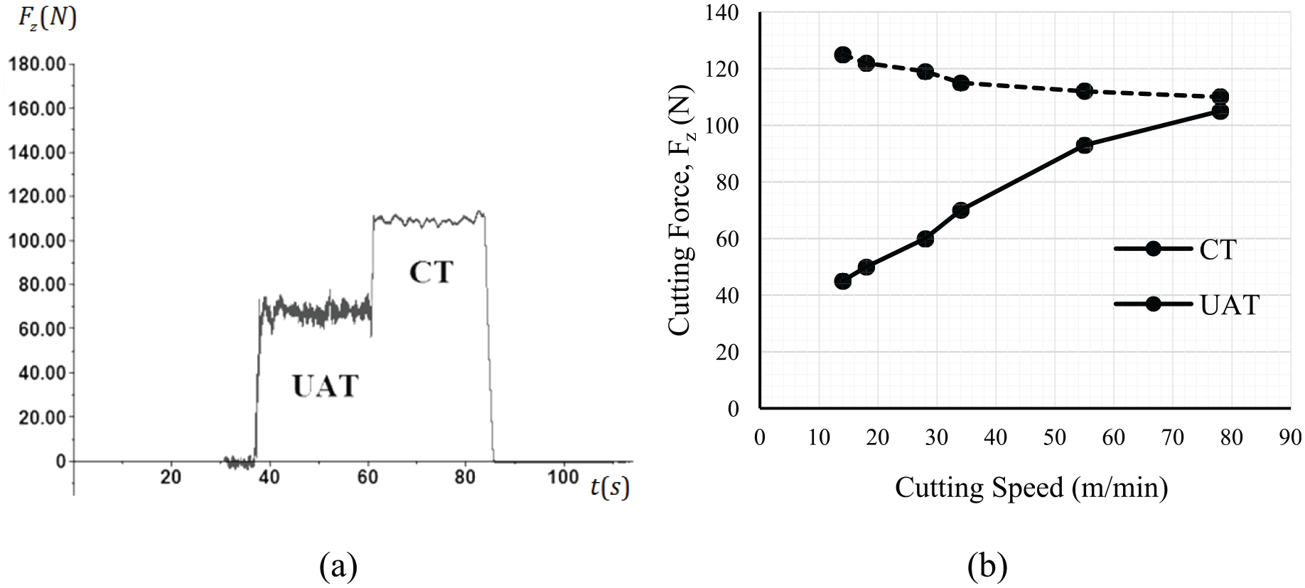
(a) Cutting force measurement at VC = 34 m/min and (b) cutting forces of CT and UAT in different cutting speeds.
Results and discussions
In this study, the experiments were conducted in four main phases, CT, UAT, CT and UAT with modified tool in which the cutting edge was filleted slightly. The results are represented in the following sections.
CT and UAT with ordinary tool
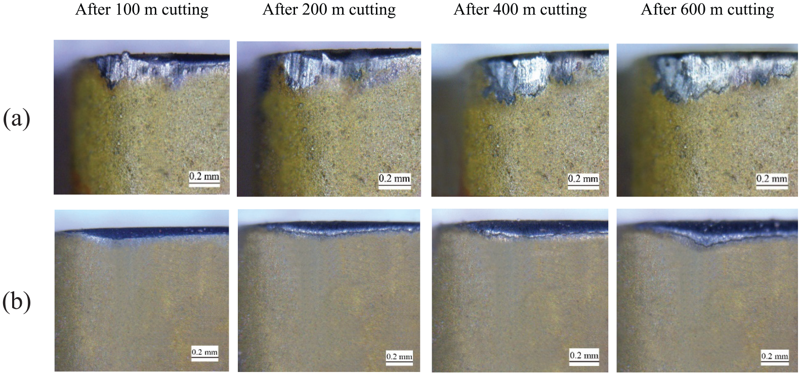
According to the experimental results of tool flank wear measurements, it was observed that the UAT technique has almost no improvements on tungsten carbide tool flank wear in the case of hardened alloy steel unless the cutting edge of the tool is modified. As illustrated in Figure 5(a) and (b), tool flank wear in UAT while using the ordinary tool is almost like that in conventional method. The most problematic phenomena observed in this method was the tool chipping and tool nose fracture at the beginning of cutting process. This fact is caused by vibro-impact characteristic of UAT and the inability to withstand the high frequency impacts of the sharp cutting edge of the tungsten carbide tool. According to the digital microscopy results (Figure 5(b)), it was observed that in the UAT technique, the sharp cutting edge of the tool is broken in the early stages of turning, so in some cases the tool flank face was heavily scratched and also the wear profile was so uneven. It got worse in the case of relatively high cutting speeds, so the cutting edge or the nose of the tool failed catastrophically. The microchipping of tool edge after short length of cutting was investigated by scanning electron microscope (SEM) that can be seen in Figure 6.
Ordinary tool flank wear: (a) CT and (b) UAT at VC = 28 m/min.
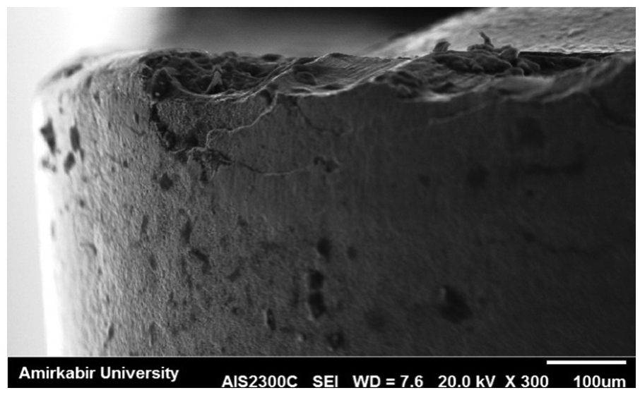
SEM photography of an early ordinary tool chipping in UAT process after few cutting distance.
CT and UAT with modified tool
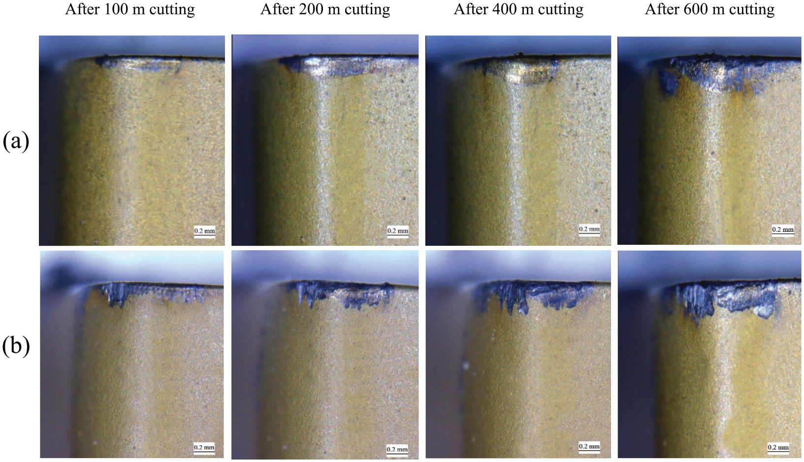
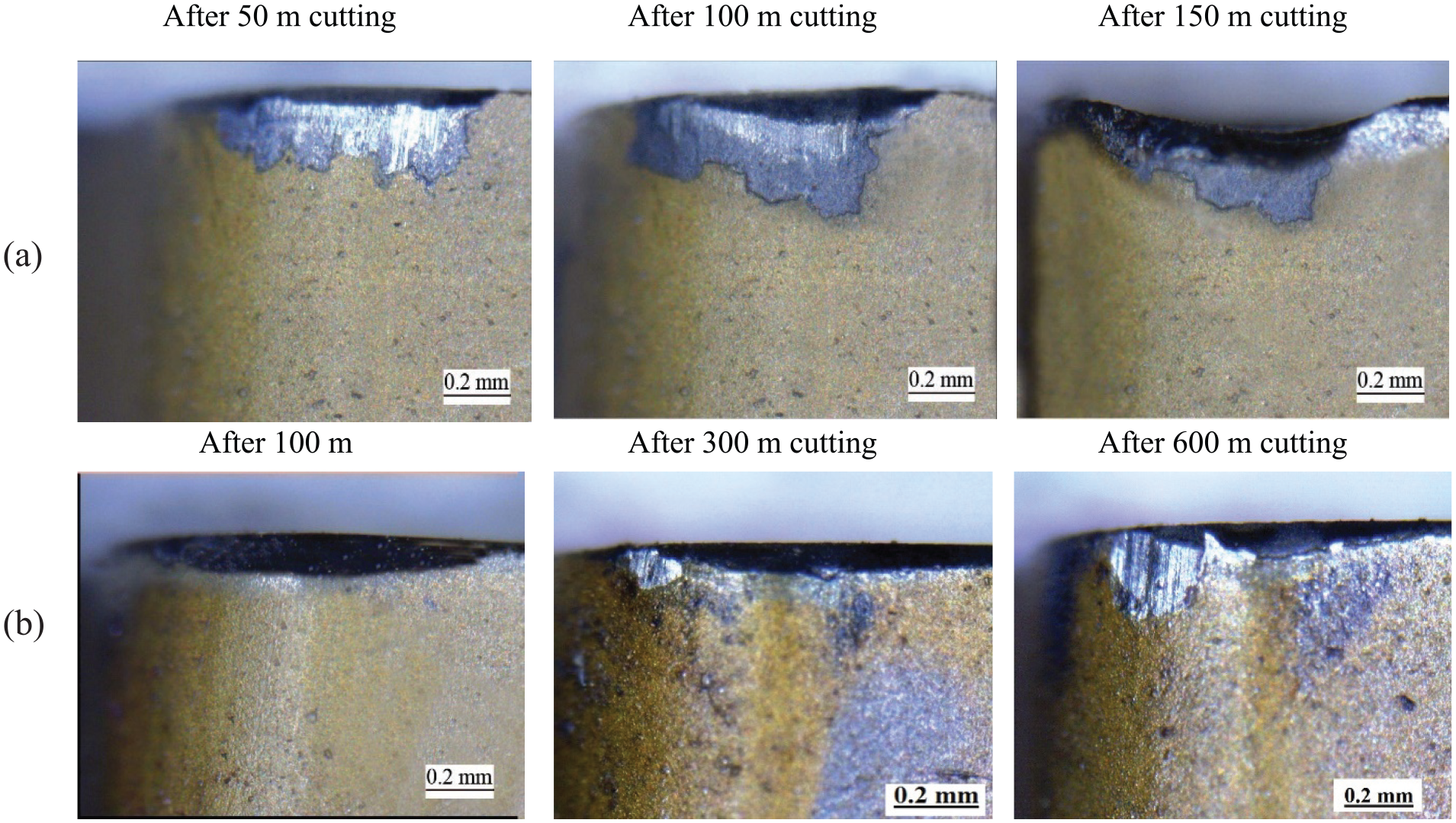
After modification of cutting edge (filleting the cutting edge by soft sandpaper), the results were dramatically changed, so the flank wear was significantly reduced, no rough scratches were observed in tool flank face and the flank wear profile got more uniform as presented in Figure 7. Another advantage of this simple tool modification was the higher strength of the tool in the case of higher cutting speeds comparing to the CT or the UAT with ordinary tool so that no tool nose fracture or catastrophic fail was observed even close to critical cutting speeds. Figure 7 shows that the wear of the modified tool in UAT technique is significantly less than the tool wear in the CT and the UAT with the ordinary tool in the wide range of cutting speeds; however, this advantage reduces in high cutting speeds.
Flank wear of modified tool: (a) CT and (b) UAT at VC = 28 m/min.
Cutting stability and BUE elimination
An outstanding achievement of using UAT was the capability of this technique to perform turning process in low cutting speeds (14 m/min < VC < 18 m/min) more convenient compared to the CT method as can be seen in Figure 8. Cutting process instability with large unexpected vibrations is the most commonly observed problem in low speed turning of hard materials which apply intensive fluctuating forces on the cutting tool, causes tool chipping, high tool wear rate and premature tool failure.31,33
Flank wear: (a) after 200 m and (b) after 400 m cutting distance.
In CT method, hard turning in low speeds was very difficult and produced intensive unexpected machine vibrations, loud machining noises, chatter and consequently high wear rate and low surface quality. In contrast, the UAT with modified tool achieves very good improvements in mentioned condition so that no chatter and noise were observed. These achievements were obtained in the UAT states (application of modified or ordinary cutting edge) except that the tool wear was not improved in the ordinary type of tool. Therefore, in some cases, the tool wear and fracture was more intensive in comparison to CT method. Figure 9(a) illustrates a high tool wear and tool failure in CT method which was observed in 14 m/min cutting speed. In contrast, Figure 9(b) shows a low tool wear in UAT method with modified tool in the same speed in which the flank wear profile was more uniform and a very low wear rate was observed.
Flank wear at VC = 14 m/min: (a) CT and (b) UAT with modified tool.
It was also observed that the UAT effects on the BUE generation, obviously. In this investigation, a significant removal of BUE was observed by utilizing UAT with modified tool. Figure 10(a) shows a BUE formation in CT process at 18 m/min cutting speed. Figure 10(b) shows that the BUE has broken off and has left a pit on the tool. Subsequently, a new BUE has been formed on the tool which is shown in Figure 10(c). In contrast, the UAT with modified tool achieves elimination of BUE as shown in Figure 10(c)–(e).
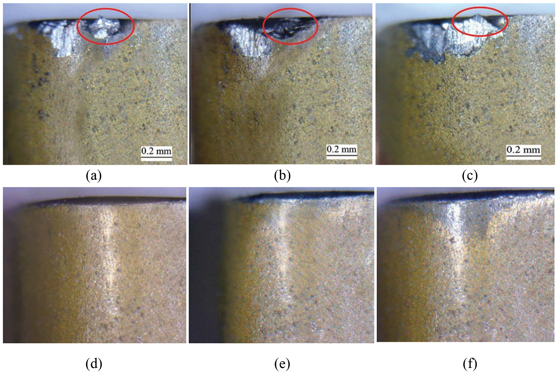
BUE: (a) BUE generation in CT; (b) BUE breaking off and leaving a pit; (c) formation of further BUE; (d), (e) and (f) elimination of BUE utilizing UAT with modified tool.
Comparison of tool flank wear in different processes
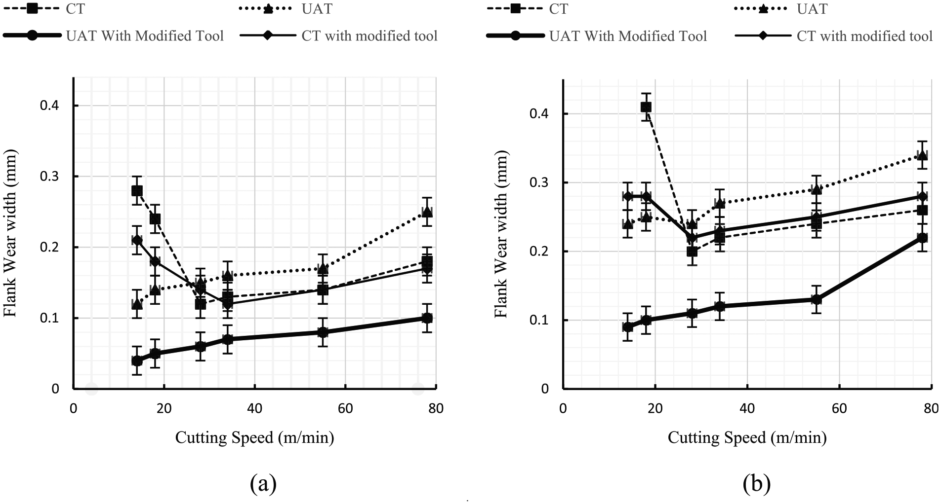
CT of hardened AISI 4140 was performed difficultly as expected. The CT experiments were carried out very difficult in low cutting speeds such as 14 and 18 m/min, so the process produced intensive machine vibrations and high tool wear rate where flank wear reached 0.3 mm. The modified tool only made slight changes in wear state and brought a small rise of durability to the cutting tool (Figure 11(a) and (b)).
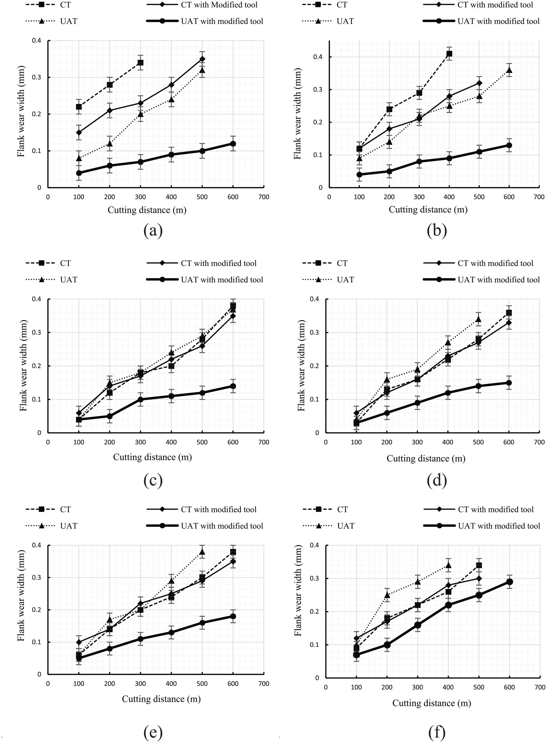
Flank wear for different cutting speeds: (a) VC = 14 m/min, (b) VC = 18 m/min, (c) VC = 28 m/min, (d) VC = 34 m/min, (e) VC = 55 m/min and (f) VC = 78 m/min.
The CT process got more convenient in higher cutting speeds such as 28 and 34 m/min, but the tool wear rate remained in large values. In other words, tool wear in cutting speeds of 28 and 34 m/min is lower than the result of cutting speeds of 14 and 18 m/min as illustrated in Figure 11(c) and (d).
At low cutting speeds such as 14 and 18 m/min, the ultrasonic vibrations made the process more stable compared to the CT processes and eliminated the intensive unexpected machine vibrations and brought a reduction in tool wear as shown in Figure 11(a) and (b). In the UAT, the tool flank wear was deteriorated at higher cutting speeds and reached to the CT process as presented in Figure 11(c) and (d). Even at cutting speeds of 55 and 78 m/min, the tool showed a lower durability and higher wear compared to the CT process (Figure 11(e) and (f)).
According to Figure 11, it is clear that the wear of the modified tool in UAT technique is significantly less than the CT and UAT with the ordinary tool and has shown a higher durability in the wide range of cutting speeds; however, this advantage reduces in high cutting speeds. It is clear that the modified tool has achieved notable improvement in tool flank wear, so the tool flank wear at VC = 14, 18, 28, 34, 55 and 78 m/min in UAT with modified tool is about 20%, 25%, 40%, 50%, 55% and 75% of the CT, respectively (Figure 11).
At first sight, maybe there were some concerns about the tool life, machining accuracy and resultant surface finish, if a nitride-coated tool is abraded before use. Also this would seem a risky technique, but as shown, this change in cutting edge, by removing the sharp edge of cutting tool, prevents the microchipping in the tool nose after machining of short length, particularly for the machining of very hard materials, and increases the tool life.
Analysis of variance
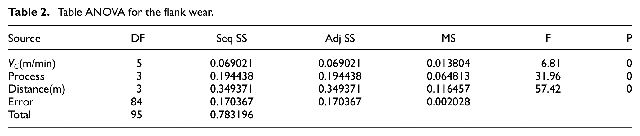
Analysis of variance (ANOVA) is a strong method for appointing the conclusion, concerning which parameters affect the response of the inquired process through the series of experimental results. In this study, the ANOVA has been employed by Minitab to investigate the influence of cutting parameters on the flank wear (Table 2). Three parameters are as cutting speed (VC), process type (CT, UAT, CT and UAT with modified tool) and cutting distance (100, 200, 300 and 400 m). These analyses were carried out for a level of significance of 5%, that is, for a level of confidence of 95%.
Table ANOVA for the flank wear.
Conclusion
The tool flank wear investigation in the UAT and CT methods was the main aim of this study. An appropriate experimental configuration was designed to investigate the UAT of hardened alloy steel using tungsten carbide tool. The experiments were conducted in four main phases: CT with ordinary tool, CT with modified tool, UAT with ordinary tool and UAT with modified tool. Based on the experimental results, the following conclusions can be drawn.
At low cutting speeds such as 14 and 18 m/min, CT process associated with intensive unexpected machine vibrations which apply intensive fluctuating forces on the cutting tool, high tool wear rate and premature tool failure. On the other hand, in UAT, application of ultrasonic vibrations eliminated the undesired vibrations, so more stable process was achieved.
It was observed that in the UAT of hardened alloy steel, the sharp cutting edge of the tool was broken in the early stages of turning, so in some cases the tool flank face was heavily scratched and also the wear profile was very uneven. By modification of the cutting edge of the tool, the flank wear was significantly reduced, no rough scratches were observed in the tool flank and the flank wear profile got more uniform.
It was observed that the UAT technique has almost no improvements on flank wear of ordinary tungsten carbide in case of hardened alloy steel. The main problem in UAT is microchipping of the tool edge after short length of cutting process that makes the tool unusable.
Results showed that the wear of the modified tool in UAT technique was significantly less than tool wear in the CT and the UAT with the ordinary tool in the wide range of cutting speeds; however, this advantage reduced in high cutting speeds. The modified tool achieved notable improvement in tool flank wear, so the flank wear at VC = 14, 18, 28, 34, 55 and 78 m/min, in UAT with modified tool was about 20%, 25%, 40%, 50%, 55% and 75% of the CT, respectively. The UAT with the modified tool demonstrated outstanding capabilities in reduction of cutting forces and tool flank wear especially in turning with lower ranges of cutting speed.
Footnotes
Declaration of Conflicting Interests
The author(s) declared no potential conflicts of interest with respect to the research, authorship and/or publication of this article.
Funding
The author(s) received no financial support for the research, authorship and/or publication of this article.