
Abstract
This article introduces the design of a robot end effector, which can perform constant force grinding on a curved surface using a brush tool without accurately measuring the geometric data of the workpiece. It uses a bidirectional cylinder and spring to create a force balance system as an additional servo degree of freedom to control the grinding brush. The system adopts impedance control method, establishes a complete electric pneumatic model, and uses PID controller to control contact force by adjusting pneumatic pressure to maintain a constant grinding force on the surface. The test results indicate that the system can perform effective rust and paint removal tasks. For paint removal, the removal rate has been proven to be 99.3% through measurement using image processing software, while for rust removal, the results are at a similar level but reliable and quantifiable measurement methods are still being studied. The end effector can be installed on most general-purpose robots for grinding and has potential application value.
Introduction
Robot grinding is an important field of robot application and is attracting more and more scientific research attention. Grinding with steel wire brush is essential in the fields such as rust removal, paint removal, deburring, and surface scraping, but there are few reports on robot grinding with steel brush tools. Instead many studies focus on rigid tools such as grinding wheels, sandpaper and abrasive belts etc.1,2 There have been studies on brush characteristics and polishing effects,3–6 but complete robot grinding solution suitable for brush tools is rarely seen.
With the development of intelligent manufacturing technology, the demands for automated removal of paint, rust, micro burrs, and surface scraping are rising. Although several major international manufacturers such as Pushcorp in the United States, SHL in Germany, and MEPSA in Spain have developed some grinding robot end effectors, it is rare to find a design to be particularly suitable for steel wire brush grinding.7–10 So far, most rigid grinding robots are often position controlled and the robot end trajectory control is particularly important. Rigid grinding normally needs to acquire precise workpiece geometric data, plan an accurate grinding path using interpolation algorithms11–13 such as cubic splines, trigonometric splines or polynomial splines, and then employs suitable sensors and error composition algorithms to construct a control loop.14–17 Since a brush is a flexible body, there is not too much concern about position error, but force control is important. Studies18–20 suggest grinding robot force control is mainly classified into three types, namely passive compliance control,21,22 active control23,24 including impedance control and hybrid control.
The impedance control18–20,23,24 is closely related to the research goal as it tries to establish a dynamic relationship between the robot’s end effector force and its position deviation, and achieve the goal of controlling the end effector force by controlling the robot’s displacement, ensuring that the robot maintains the desired contact force in the constrained direction. Using impedance control, an end-effector with an accurate theoretical model should be constructed, and then control the servo displacement using PID controller25–27 to maintain constant grinding force. The end effector should be light in weight but has strong stability to withstand large torque and high rotational speed required by the brush, and it should provide an extra degree of freedom to allow adjustment and to apply adequate vertical pressure on the brush. Since brush oscillation introduces control difficulties, relative studies on frequency analysis28–31 are also referenced and utilized in this study.
Based on the above knowledge, it was decided to use a pneumatic cylinder as the end effector servo actuator, since cylinder is strong in structure whilst air is compressible and shows good damping effect. Proportional electromagnetic valve and PID control algorithm will be used to adjust cylinder inlet air pressure so as to adjust brush height and force to form a constant force grinding system.
Brush control strategies
The purpose of this project is to design a robot end effector that can perform constant force grinding on curved surfaces without accurately measuring the geometric contour of the workpiece. According to previous research,5,6 the operating parameters that affect the grinding efficiency of wire brushes include contact force, tilt angle that is, the angle that brush axis is inclined from the normal direction, spindle speed, and forward speed. A three degree-of-freedom Cartesian coordinate experimental platform has been designed to determine the appropriate brush operating parameters. The platform can achieve linear movements in three-dimensional space, and it has an additional joint that can be adjusted by screws to tilt the end effector. The photograph of the platform is shown in Figure 1.

Platform for testing brush operating parameters and image processed test plate: (a) The hardware of the test rig and (b) image processed test plate (P = 38.12%).
To assess the grinding effectiveness, tests were performed on painted steel plates, and OpenCV image processing codes were written to compare the changes of the paint layer surface. The captured color image was grayscale processed, and pixels with a grayscale lower than a threshold were converted to black, and pixels with a grayscale higher than the threshold were converted to white, as shown on the right of Figure 1. Finally, count the white and black colors of each pixel to calculate the paint removal rate P.
To investigate the impact of various factors, single factor experiments were conducted using the parameters shown in Table 1. The parameters in the table use values marked with * symbol by default. When evaluating a certain factor, the value of that factor will be tried one by one through the values in the row, meanwhile other factors use the default values. The experimental results were evaluated using the above image processing method, and several resulting images are shown in below Figure 2.
Parameters for single factor tests.


Photographs of paint removal experiment results: (a) P = 89.01%, (b) P = 95.07%, and (c) P = 97.63 %.
Above tests were carried out under conditions of (a) F = 30, T = 30, R = 8000, V = 16, and (b) F = 25, T = 30, R = 8000, V = 8, as well as (c) F = 30, T = 30, R = 8000, V = 8. After testing different parameter combinations, the curves of the paint removal effectiveness is shown in Figure 3. Contact force is crucial for grinding efficiency. As the contact force increases, more material is removed but it may lead to excessive scratching to the workpiece surface, meanwhile it consumes more power.

Paint removal single factor test results.
The impact of tilt angle is that it affects how the steel wire tip is perpendicular to the workpiece. Because brush wires originally flip out forming a skirt shape, a proper tilt angle would make the brush front edge more perpendicular to the workpiece. As the tilt angle increases, the contact surface first changes from the side of the steel wire to the tip of the wire, and then changes to the other side. 10 The contact effect changes form pressing to scratching and to pressing again, thus the grinding effect first increases and then decreases. In practice this parameter can be set to constant as long as the optimal value is found out.
As the spindle rotational speed increases, the grinding power increases, thereby accelerating the speed of thermoplastic deformation and increasing the grinding depth. Whilst when the rotational speed is high, it will increase the centrifugal force thus increase the inclination angle of the steel wires, which reduce the grinding force. The forward speed mainly affects the contact time between the steel wires and the workpiece. As the forward speed increases, the contact time is reduced thus the paint removal rate appears to decrease.
After assessing sufficient experimental samples, the efficiency of wire brush grinding can be well understood. For the selected specimen brush in the lab, which is 0.2 mm in wire diameter and 1200 wires in total number made by the factory without further argument, a parameter combination of 30N contact force, 35° tilt angle, 11,000rpm rotational speed and 8 mm/s forward speed has been determined to provide most efficient grinding. These operating parameters require an effective robot end effector to implement and the design process is described below.
Robot end effector design
In practice, a robot end effector needs to maintain a certain contact force, a proper tilt angle, and a sufficient speed for continuous grinding. For a workpiece surface not gone through precise measurement, it is very difficult to maintain constant force and inclination angle due to abrupt curvature changes. Many existing grinding robots need to measure the geometric surface contour in advance, resulting in increased costs and decreased efficiency. For the current design, the concept of the grinding path implementation is shown in Figure 4. For an unknown working contour, suppose three waypoints a, b, and c can be defined using robot teaching methods. Most universal robots can use joint movement commands (usually MovJ) to walk along an arc passing a, b, and c. The robot path may not completely fit on the actual curvature of the working surface, but the error is small if the distance between a, b, and c is small, besides if appropriate adjustments can be made to the axial height of the end effector. It was decided to use a pneumatic device to adjust the end height and maintain the contact force on constant level. This does not require complex devices in the robot body and robot controller. It is suitable for ordinary domestic robots or even stepper motor robots, and therefore has a high cost-effectiveness competitiveness.
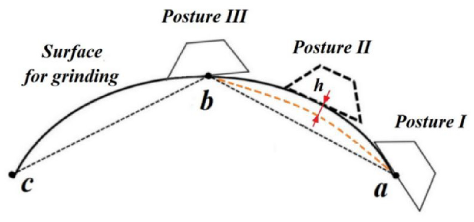
Robot grinding path determination method.
The end effector needs to be universal and can be applied to most lightweight industrial robots, so the weight of the end effector should be reduced as much as possible while meeting performance indicators. The mechanical structure design of the end effector is shown in the following Figure 5.

The end effector structure and mechanical model.
The device consists of a low friction cylinder, two springs, pressure sensors, DC motors, electrical proportional valves, and other components. The cylinder is the main motion control component, which is connected to the pressure sensor through a connecting plate. The pressure sensor is a ring type one DOF force sensor and it connects the cylinder with the lower half through the motor frame. Although a 6-DOF sensor shall be more accurate it has not been installed at this stage for economic reasons. During the grinding process, when the brush comes into contact with the workpiece, the brush generates a force on the workpiece while the workpiece gives a reaction force of the same size on the end effector, which is transmitted to the pressure sensor to achieve contact force measurement. When there is a deviation between the measured force and the set value, the controller will adjust the air inlet pressure of the cylinder through the electromagnetic proportional valve. The cylinder starts to move to maintain the contact force constant.
The cylinder has two parallel auxiliary rods, and the two springs are installed on the rods. The cylinder only uses the lower air inlet to supply air providing an upward lifting force, while the compression of the springs provides an opposite pushing force. As the springs constantly generate pushing force according to the cylinder length, only control the compression air pressure can adjust the pressure equilibrium. This cylinder-spring dual balance design greatly reduces the difficulties in bidirectional air pressure control. The simplified mechanical structure model is shown on the right in Figure 5. Note the weight of the motor itself contributes to the contact force. When there is no air pressure the weight is connected to the springs, so it can be assumed the effect of the weight is the same as using longer springs. This offset needs to be remedied in the contact force measurement.
To effectively control the grinding process, it is necessary to establish a mathematical model for the end effector as a crucial step of impedance control. By analyzing the force acting on the end effector, the second order equilibrium of the end effector subjects to the influences from the cylinder pressure, the friction, and the surface contact force applied on the brush. Therefore from Newton’s second law below equilibrium can be obtained,

where m is the mass of the end effector, x is the displacement of cylinder piston, Kv is the viscous damping coefficient, Kd is elastic coefficient of the spring, Fc is the contact force applied by the end effector, Ff is the friction force of the push rod, P is the input air pressure of the cylinder, and (Rp2-rp2) is the effective area of the cylinder.
The frictional force of the system mainly comes from the friction between the piston and the inner wall of the cylinder, as well as between the push rod and the shaft sleeve. The cylinder of the end effector is a low friction cylinder, which uses special lubricating grease and a shaft sleeve with a very low friction coefficient. Its sliding resistance is very small, so the frictional force of the cylinder can be ignored. Perform Laplace transform on the above equation (1) gives below.

The grinding contact force corresponds to contact deformation in the brush and it can be expressed as

where Kc is the equivalent brush stiffness which can be measured in experiments. Thus combine the above equations gives the transfer function for the mechanical parts of the end effector.

To derive the mathematical model of the entire system, it is also necessary to establish a mathematical model of the pneumatic system. The pneumatic system schematic is shown in Figure 6, with the input signal of the system being voltage U and the output signal being air pressure P. When the air compressor outputs air pressure, the controller adjusts the switching value of the electrical proportional valve by controlling the input voltage, thereby controlling the air pressure inside the cylinder and generating a certain thrust on the cylinder piston. The difference between this thrust and the spring force is the output force F acting on the working surface.

Pneumatic circuit of the end effector.
According to the energy conservation law, the gas flow rate entering the cylinder chamber can be represented by the rate of change in gas mass,

where Qm is mass flow rate of gas in the chamber, ρ and V are the density and volume of the gas in the chamber. Assuming that the gas in the system is ideal gas, then from the ideal gas law the following equation can be obtained,
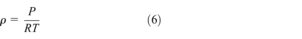
where P is pressure in the chamber, R is ideal gas constant, and T is chamber temperature. According to the first law of thermodynamics, the energy conservation equation in a cavity can be determined by below equation,
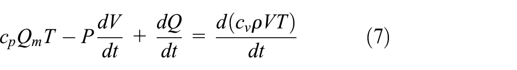
where
When the air compressor outputs gas, the gas will enter the cylinder chamber after being regulated by an electrical proportional valve. Assuming that the time for gas to fill the cylinder chamber after entering is very small and negligible, then

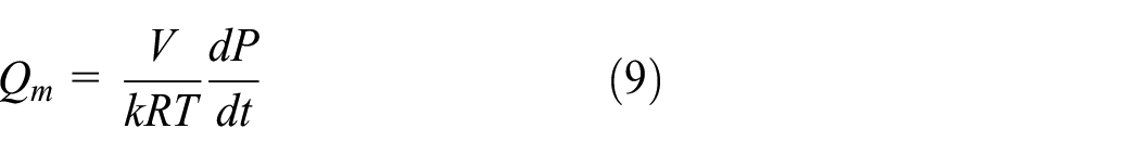
By transforming the above formula, the model of the mass flow rate in the cavity is given below.
The flow rate of the electrical proportional valve is related to the outlet air pressure Pou and input voltage U. The mass flow rate near the working point can be linearized through an electrical proportional valve to establish flow characteristic equations for outlet air pressure and input voltage as below,

where K1 is flow gain at operating point, and K2 is flow pressure coefficient. Perform Laplace transform on the above equation gives


According to the previous assumption, if the air pressure in the same space is equal everywhere, the air pressure in the outlet of the valve is equal to the air pressure in the inlet, this gives

Combine above equations gives

Based on the above, it can be seen that the dynamic structure diagram of the complete system is shown in Figure 7. Connect the transfer function of the system according to the connections between various links in the system through a structural diagram, to more vividly and clearly express the mathematical models and interrelationships of each link in the dynamic process of the system.

Combined electropneumatic model of the end effector.
The closed-loop transfer function in the figure above can be synthesized into a transfer function, as shown in below

Based on the mathematical model of the end effector, a PID controller was added in the loop as shown in Figure 8, and Simulink was used to build a simulation model of the PID control system.
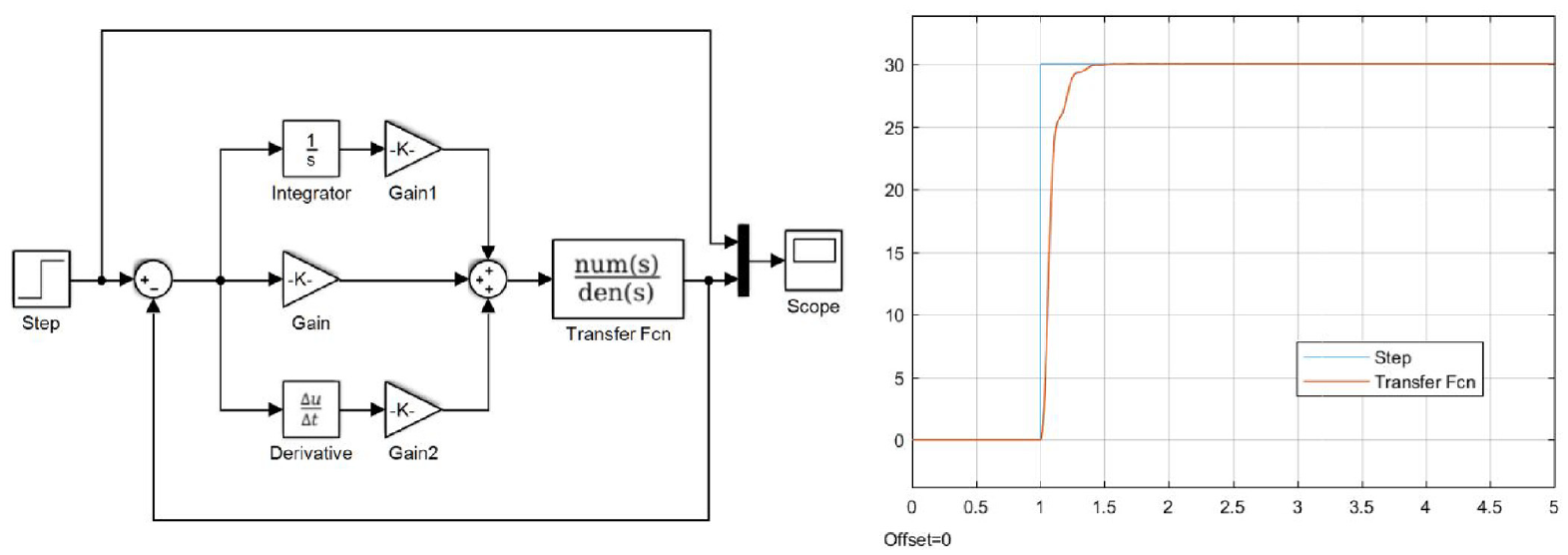
PID control model and simulation result.
From the transfer function, it can be seen that the model is a third-order system, which requires a lot of effort to adjust PID parameters. After tuning, the optimal PID control parameters for the current brush are obtained, and the system step response is shown on the right side of Figure 8. It can be seen that the system has good stability, without significant overshoot or oscillation, and the system response time is a little slow. This is partly caused by the large step amplitude and smaller pneumatic driving power. Since in actual use the abrupt changes of contact force above 5N is rare, the response time of the actual system can be stabilized within 0.1 s. After model calibration, encode the PID gain into the actual controller to construct the control loop. The control system is made on a TMS320F28335 DSP board, which has an analog input channel for reading force sensor signals and an analog output channel for adjusting the proportional valve. The signal acquisition speed can reach up to 1000 samples per second, from which error amplitude, deviation, and integration are calculated to construct a PID control loop.
Experiments
The actual equipment utilized in this project is shown in Figure 9. A UR-5 robot was employed to guide the grinding path and the designed end effector prototype was installed on the robot. Since UR5 is a 5 kg universal robot, the designed weight of the prototype is limited to 3.5 kg, and it mainly performs tasks in the up and down directions. The force sensor connecting the two parts of the end effector is surrounded by a red mounting shell, which cannot be directly seen in Figure 9, but its position is marked by a text label. The grinding path was defined using robot way points and MovJ commands, and the end contact force was controlled by the pneumatic proportional valve using a TMS320F28335 DSP controller board. The PID algorithm was written in the DSP board to perform automatic force adjustment.
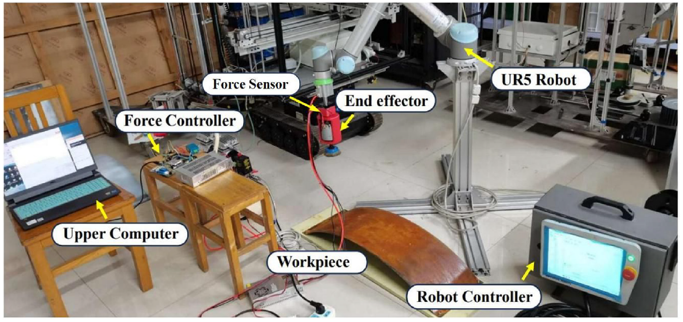
The equipment for brush grinding experiment.
The arc-shaped test plates were made of Q235 steel bent to a section of a sinusoidal curve, however the shape was not remembered and used by the robot, because the purpose of this project is to validate robot utilization for any workpiece shapes through general teaching mode in the robot front panel. Such an application is like working in a garage where there are many different types of cars and it is impossible for operators to measure each car, but he can perform robot grinding with teaching mode by defining a small number of posture points. As many scholars concluded that the forward kinematic model of UR-5 robot can be described as below,


and the robot support complex interpolation algorithms such as spline interpolation and five order interpolation to control position, velocity and acceleration. However, the aim of this research is to use a simplest teaching mode in a complex environment, thus it only need to define a continuous velocity path and a few posture points as in Figure 4, thus only cubic interpolation is adequate for this project.
During tests it was noticed that the wire brush exhibits significant high-order resonance phenomenon since the brush is composed of thousands of steel wires, which means effective filtering of the measured force is required. The force data after using moving average filtering is shown in Figure 10, and it can be seen that the force disturbance caused by resonance is limited to 0.05N.

Raw data of the resonance phenomenon of a free rotating brush.
The step signal following test results are shown in Figure 11, indicating that the system has a slightly longer response time to changes above 10N, but exhibits reasonable stability after convergence.

Step response and contact force maintaining test results.
The measured force data of the system using different forward speeds for grinding on curved steel plates is shown in Figure 12. It can be seen that in addition to a slightly slower response time to large step signals at the beginning, the system performs well, especially demonstrating reliable stability at lower forward speeds. When forward velocity is greater than 15mm/s, the system tends to get difficulties to maintain a stable contact force and oscillations arise. This can be improved in a later design using more powerful actuators and more robust mechanical structure design.

Contact force maintaining tests with different forward speeds.
The grinding effect test was conducted on the curved Q235 steel plate, and the rust removal test procedures were recorded and shown in Figure 13. It can be seen that after the brush passes, most of the rust can be effectively removed. However, due to the influence of various factors such as environment, material, time, and corrosion depth on the formation of rust, it is difficult to summarize a quantifiable measure to evaluate the rust removal effect. The related issues are still the focus of later research.
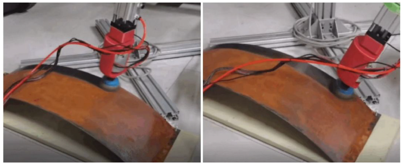
Rust removal test on a curved steel plate.
Paint removal test was conducted on another specimen plate and the process was recorded as shown Figure 14. The steel plate was sprayed with white car exterior paint to form an average paint layer of 100um, and the paint removal effects was tested continuously. It can be seen that the majority of the paint was peeled off very effectively. The surface of Q235 steel plate was originally silver, but over time, due to air oxidation, the surface gradually darkened. Above all, in terms of pain removal purpose, the end effector performed very stably, and the paint removal rate was achieved to 99.3% measured by the image processing method mentioned in Section 2.

Continuous paint removal test.
The above experimental results suggest that the design scheme of the end effector is feasible and the grinding effects are well acceptable.
Conclusions
This article introduces the design of a robot end effector that can perform constant force grinding on curved surfaces without accurately measuring the geometric contour of the workpiece. The end effector provides an additional servo degree of freedom, and uses impedance control method to control the grinding force on a constant level. The end effector is suitable for other types of flexible polishing tools, and its major design steps and outcomes are as follows.
(1) The effectiveness of brush grinding was tested in extensive exploratory experiments to determine grinding control strategies. The experiments decide the most important operating parameters, such as brushing force, rotational speed, inclination angle, and forward speed, so as to determine the brushing postures that should be maintained during the grinding process.
(2) The hardware of the end effector consists of a cylinder, force sensor, and spring, forming an adjustable force balance system. The control system reads the signal from the force sensor, calculates the amplitude, deviation, and integration of the error, and then uses PID control method to adjust the pneumatic servo valve based on the impedance control model. This enables the output of the force balance system to be quickly adjusted, allowing the brush to maintain a constant force on the surface of the workpiece.
(3) The robot continuous grinding path can then be defined using built-in teaching mode following knowledge about a few posture points learned in step 1. A simple built-in cubic interpolation algorithm can complete the path planning process, as the end effector can adapt to the errors generated in the grinding path. This enables the use of soft tools to polish workpieces without measuring their geometric data.
(4) The experiments showed that the paint removal rate measured by image processing methods reached 99.3%, achieving good results.
This end effector is used for pressure regulation in the direction of the end axis and can be installed on most general-purpose robots for grinding. It has a simple structure, is easy to implement, has strong applicability, and shows considerable market competitiveness.
Footnotes
Handling Editor: Chenhui Liang
Declaration of conflicting interests
The author(s) declared no potential conflicts of interest with respect to the research, authorship, and/or publication of this article.
Funding
The author(s) disclosed receipt of the following financial support for the research, authorship, and/or publication of this article: The study was funded by Special fund for Mount Taishan Industrial Leading Talent Project, China.