
Abstract
The 120-type air brake system is unique around global rail industry and critical for Chinese freight train operation. Existing research about its simulations does not include detailed models for the emergency brake valves. This paper filled this research gap by developing a detailed fluid dynamic air brake system with a focus on the emergency brake valve. The working principle of the emergency brake vale was reviewed. The brake system model was based on gas flow governing equations (mass and momentum) and orifice flow equations. The model was validated by comparing with measured data from a 150-wagon train. Four braking scenarios were compared. The simulated maximum cylinder pressure was only 5 kPa out of the range of the measured data. The maximum difference regarding the time when cylinder pressure reaches maximum pressure was 4 s. The simulation results have also shown variable switch pressure points for the two-stage brake valve. This is agreed by the measured results and was not shown in previously published research.
Introduction
Freight railway transport stands as an essential backbone for the Chinese economy, playing a pivotal role in the seamless movement of goods, commodities and trade items. The expanse of the country coupled with its robust industrialization drive mandates the need for a reliable and efficient railway system to ensure uninterrupted supply chains. Within this vast railway network, a freight train’s brake system is paramount, serving as the guardian of safety and smooth operation. Ensuring a properly functioning brake system is, therefore, not just about efficient transportation but also about preventing potential catastrophes. This underscores the importance of brake system research, which seeks to optimize performance and safety standards of freight train operations.
A broad overview of the methods employed for air brake modelling was given in a comprehensive international survey. 1 These methodologies for air brake models have traditionally been categorized into three main groups. The first encompasses fluid dynamics models, where fluid dynamics of brake pipes are meticulously modelled using partial differential equations which delineate governing laws such as conservation of mass, momentum balance and energy balance. These models, exemplified in References 2–8, primarily focus on the dynamics of brake valves by modelling air flows across various chambers, volumes and cylinders. The second category is constituted by empirical models.9–14 As the name suggests, these models avoid the intricate modelling of fluid dynamics behaviour and instead simulate brake behaviour by examining the temporal shifts in pressure distributions across the brake cylinders. Key characteristics, ranging from maximum brake pressures to pressure change rates and time delays, are considered. Lastly, the third category integrates both previous methods, dubbed fluid-empirical models.15–20 Here, while brake pipes are modelled grounded in fluid dynamics principles, brake valves employ an empirical approach. It’s essential to highlight the distinction between empirical air brake models (encompassing the entire system) and empirical brake valve models; while the former responds to direct train driving commands from operators, the latter uses brake pipe pressures as inputs.
As reviewed in Wu et al., 1 among the popular freight train air brake systems (ABDX, KE, WF5, 120 series, and KAB60), only ABDX and 120 series systems have emergency portions. A closer comparison of the ABDX 21 and 120 series 22 brake systems indicates that these two valves have very different working principles for emergency braking. The former uses an extra emergency brake reservoir. During emergency braking, the valve connects the emergency brake reservoir to brake cylinder. Under this situation, both auxiliary reservoir and emergency reservoir inject pressurized air into the brake cylinder and so to obtain the pressure that is required for emergency braking. The 120 series brake system, on the other hand, does not use emergency reservoir. Its emergency valve opens a large air outlet for the brake pipe on each individual wagon during emergency braking. Pressurized air in the brake pipe is exhausted rapidly to create emergency braking. More information regarding this type of emergency braking will be introduced later in this paper.
Having discussed the difference between these two emergency braking functions, it can be claimed that the emergency brake valves of the 120 system is unique and requires special modelling procedures. A review of open literature regarding the modelling of 120 brake system2,6–8,22–25 indicates that none of the published research has included detailed modelling for the emergency brake valves of the 120 brake system.
Addressing this research gap, the focus of this paper is to present a fluid dynamic air brake valve model tailored for the Chinese freight air brake system, with a specialized emphasis on a detailed emergency brake valve. The paper starts with and explanation on the working mechanism of the emergency valve, then delves into the intricate fluid dynamic modelling of the same. After this, the proposed model will be validated against measured data. The paper will also demonstrate that the detailed emergency brake valve model can provide better simulation of the emergency braking behaviour.
The emergency brake valve in 120 brake system
The 120 brake system consists many components including intermediate body, main valve, semi-automatic release valve and emergency valve. Structural details and working principles of the first three components have been well discussed in References 2, 6–8, 22–25, they are not repeated in this paper. The following contents will be focused on the structural details and working principle of the emergency valve.
An illustration of the emergency brake vale is presented in Figure 1. The valve consists of the primary piston, stabilizing springs, exhaust valve, piolet valve and many other small details. The function of the emergency valve is to accelerate the exhaust of the train pipe during emergency braking (emergency localized depressurization) to ensure the reliability of the emergency braking action, enhance the sensitivity of emergency braking, and thereby improve the speed of the emergency braking wave.

Illustration of emergency brake valve of the 120 brake system: (a) non-emergency position and (b) emergency position.
As shown in Figure 1, the volume above the emergency piston communicates with the emergency chamber; the lower volume of the emergency piston communicates with the train pipe. The volume underneath the exhaust valve also communicates with the train pipe. Inside the axial hole of the emergency piston rod, there is a limiting hole marked as ‘III’, which is used to control the speed at which the air pressure in the emergency chamber flows back to the train pipe. This ensures that during emergency braking, there is a sufficient pressure difference on both sides of the emergency piston to push the emergency piston downward. This will first push the pilot valve open through the push rod, and then push the exhaust valve open, achieving the purpose of initiating emergency braking. At the same time, during regular braking, it ensures that more air from the emergency chamber can flow back to the train pipe to ensure that there isn’t enough pressure difference on both sides of the emergency piston to push it down and open the pilot valve. The aperture of the limiting hole III should be appropriately designed; if it’s too large, it will reduce the sensitivity of emergency braking, and if too small, it will affect the stability of regular braking.
The upper part of the emergency piston rod has a radial limiting hole marked as ‘IV’, which is used to control the speed at which the train pipe inflates the emergency chamber. This ensures that the pressures on both the upper and lower sides of the emergency piston are balanced, preventing the emergency chamber from inflating too quickly and accidentally initiating emergency braking.
On the lower part of the emergency piston rod, 13 mm from the bottom, there is a small hole marked ‘V’. This is used to control the speed at which the air pressure in the emergency chamber is released to the atmosphere after emergency braking. This ensures that after emergency braking, the emergency piston in the lower position will only move back up after a certain period, ensuring that after emergency braking, the train must stop and charge the train pipe to release the train, and then operate again.
When the emergency piston is in the uppermost position, there is a 3 mm gap between the bottom of the emergency piston rod and the top end of the pilot valve. When the emergency piston moves downward by 3 mm, the emergency piston rod will touch the pilot valve push rod. If it continues to move downward, it will open the pilot valve; if the push rod is pressed by the emergency piston rod and continues to move downward by more than 1 mm, the exhaust valve will be pushed open. Under this condition, pressurized air from the brake pipe will be exhausted at a very fast speed. This function can be regarded as that during emergency braking, the brake valves provide one extra and large air outlet for each individual wagon of the train.
To improve train dynamics during emergency braking, the 120 brake system has also added a two-stage valve as shown in Figure 2 to reduce the brake cylinder pressure increase rate after a certain period of time. The emergency two-stage valve is not located in the emergency valve but in the 120 main valve. This is because the two-stage valve regulate the air passage from the auxiliary reservoir to brake cylinder and the passage is also used by all other service brake action.
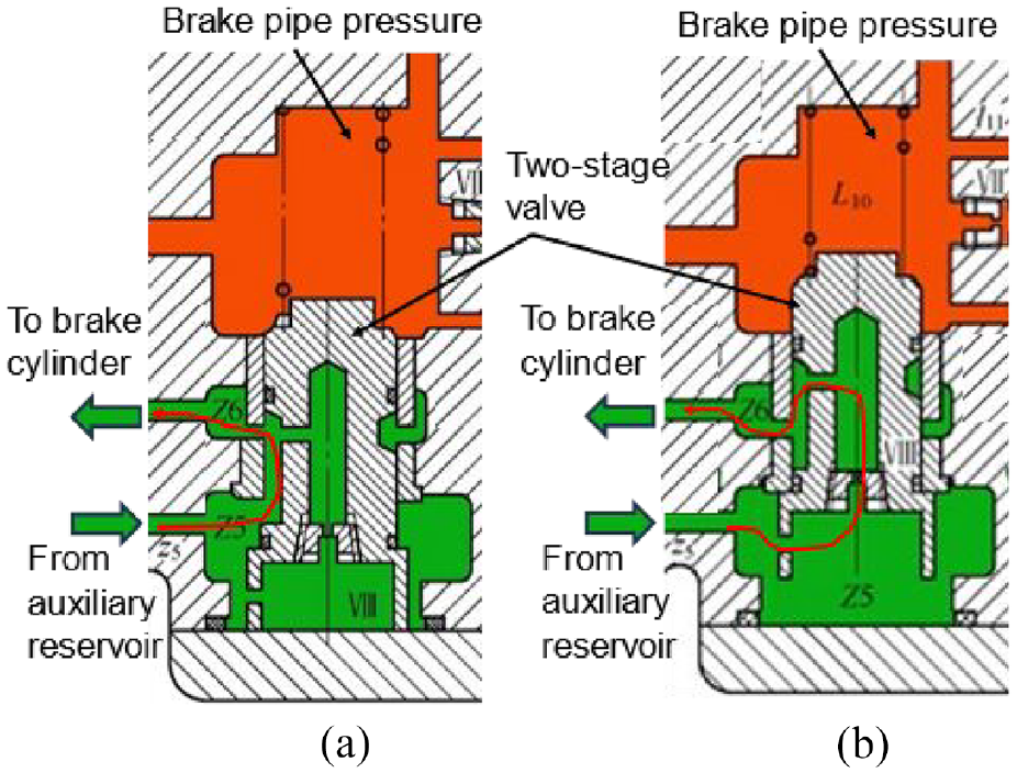
An illustration of the emergency two-stage valve: (a) the first stage and (b) the second stage.
The upper volume of the emergency two-stage valve connects to the train pipe. And the lower volume provides a passage between the auxiliary reservoir and brake cylinder. Under normal conditions, the train pipe air pressure in the emergency two-stage valve spring and its chamber keeps the emergency two-stage valve rod in the lower open position; the air passage is shown in Figure 2(a). During emergency braking, the train pipe air pressure is quickly released into the atmosphere, and the brake cylinder is charged. When the brake cylinder pressure jumps to 120–160 kPa (the standard jump pressure when the train pipe is set at 600 kPa), the brake cylinder pressure in the lower chamber of the emergency two-stage valve rod can overcome the combined forces of the spring tension from the emergency two-stage valve spring above and the remaining pressure of the train pipe, moving the emergency two-stage valve rod to the closed position. The so-called closed position refers to the point where the unobstructed channels around the emergency two-stage valve are cut off. Therefore, the auxiliary air cylinder pressure can only flow to the brake cylinder through the lower chamber of the emergency two-stage valve, the axial centre hole, and the upper radial hole as shown in Figure 2(b). Due to the significantly narrowed flow path, the brake cylinder pressure rises slowly. As a result, the brake cylinder pressure increases in two stages, rising rapidly at first and then more slowly, hence the name ‘emergency two-stage valve’.
From the descriptions of this section, one can comprehend that the major difference between the ABDX emergency valve and the 120 emergency brake value is that the ABDX valve uses an additional reservoir to increase the inlet pressure to the brake cylinder whilst the 120 value increases the inlet opening area to the brake cylinder.
Modelling of air brake system and emergency brake valve
As reviewed in the introductory section, a number of different methods were used for air brake system modelling. Among them, fluid dynamic air brake models possess several advantages in the realm of transportation engineering and design. First and foremost, they offer a heightened level of accuracy and precision in simulating the behaviour of air flow and pressure variations within braking systems. This intricate representation ensures that a wide range of operating conditions and configurations are accounted for, granting designers the flexibility to tweak and optimize systems for varied needs. Moreover, these models excel in predictive capacities, enabling engineers to foresee system responses under diverse scenarios. This not only streamlines the design process but also ensures heightened safety standards. Additionally, they capture intricate phenomena, from compressibility effects to transient behaviours, which are paramount for refining and enhancing air brake system performance. In essence, fluid dynamic models serve as a crucial tool in ensuring the efficiency, reliability and safety of air brake systems.
Fluid dynamic modelling of the air brake system in this paper used the gas flow method that was also used in References 2, 7, 26. In other words, the model mainly described gas flows in pipes and between connected volumes. Originally in these references, the gas flow in brake pipes was simulated by using three governing equations:

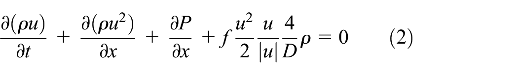

where


These assumptions will generate the following limitations: (1) the model is not able to consider the changes of cross-sectional areas caused by the hoses connecting adjacent vehicles; and (2) the model cannot consider the influences of temperature on brake performances. For example, it is known that air brakes may have lower performances in cold weather. The gas flow equations can then be solved by using the Method of characteristics as sued in References 2, 7, 26. The Method of Characteristics is a mathematical technique primarily employed to solve certain types of partial differential equations, especially those arising in hyperbolic problems. It is particularly useful for addressing problems associated with wave propagation, such as gas dynamics and shallow fluid flow. All these features fit well with the problem expressed by equations (4) and (5), which well justified the selection of this mathematic technique.
Having solved the gas flow in brake pipes, other gas flow problems in brake system modelling can be generalized as the gas flow between any two volumes. Mathematically, this can be expressed as:

where

where
Having obtained the emergency camber pressure (

where
Movement logic in the emergency valve.

Modelling of the two-stage valve as shown in Figure 2 was also based on pressure differences. In this case, the movement of the two-stage valve was determined by the pressured difference between the brake pipe and brake cylinder. Its movement logic is shown as in Table 2. To determine the exact opening of radial hole Z5, the following inversing method can be used:
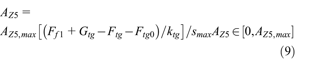
where
Movement logic in the two-stage valve.

Model validation
The validation of brake system models is crucial to ensure the accuracy of simulations, guaranteeing that the system’s real-world performance aligns with theoretical predictions, thereby enhancing train braking safety and reliability. Model validation in this paper was carried out by comparing simulation results with a set of measured results from Reference 27. Some key parameters of the measured and simulated system are shown in Table 3. The system had 150 sets of wagon brake valves. The total train pipe length was longer than 2.0 km.
Brake system model key parameters.

Four different cases of measured data were available as shown in Table 4. These data included three positions from the train, that is, the 1st (start), 75th (middle) and 150th (end). The pressure reductions in this table indicate different brake scenarios. And the values of the pressure reductions indicate the final pressure reduction in the brake pipe. In other words, the 50 kPa reduction indicates a minimum service brake; the 140 kPa reduction indicates a normal service brake; the 170 kPa reduction indicates a maximum service brake; and the emergency brake case equals to a 600 kPa reduction. Table 4 summarizes the maximum brake cylinder pressures from the measured and simulated results. From an engineering standpoint, it’s important to understand that simulations and measured data will seldom align perfectly. Simulations, by their very nature, are based on mathematical models that make certain assumptions to simplify complex real-world phenomena. These assumptions can range from ignoring minor forces to assuming ideal conditions. On the other hand, measured data is influenced by countless factors in the real world, including instrument accuracy, environmental variations and inherent uncertainties in materials and systems. While simulations can provide valuable insights and come close to real-world scenarios, the intrinsic differences and limitations of both methodologies mean that they will never be an exact match. Having understood these, it’s evident that the simulated results are in close proximity to the actual measured values for each pressure reduction level. For a 50 kPa pressure reduction, the simulations for cylinders 001, 075 and 150 exhibit a relatively narrow range of 132–137 kPa compared to the measured range of 134–145 kPa, resulting in a minor range error of just 2 kPa. At a pressure reduction of 140 kPa, the simulated data for cylinder 001 is slightly lower than its measured counterpart, but the overall range for all cylinders, 426–465 kPa, is very close to the measured range of 431–467 kPa, with a modest range error of 5 kPa. Interestingly, at the 170 kPa pressure reduction level and in the emergency scenario, the simulated data exhibits no variability among the different cylinders, while the measured data continues to present minor fluctuations. Nonetheless, these deviations are minute, highlighting that the simulations are quite accurate and reliable when validating with the measured values.
Measured and simulated maximum brake cylinder pressures.

Table 5 shows the comparisons of the measured and simulation time points when the brake cylinder pressures reach their maximum values. This is also an important parameter to assess the pressure increasing rate during the process. The results show that at a pressure reduction of 50 kPa, the maximum difference between the simulated and measured time points is 4 s, with the greatest discrepancy observed in cylinder 150. For the 140 kPa pressure reduction, the variance is again at 4 s, which can be attributed to cylinder 150 as well. A lesser discrepancy of 2 s is noticed at the 170 kPa pressure reduction, with both simulated and measured results closely aligning. In the emergency situation, the maximum difference reduces further to just 1 s. Overall, the simulated data appears to be fairly accurate when reflects with the measured data, as highlighted by the minimal time discrepancies for each pressure reduction scenario. The consistency of these minor deviations underscores the precision of the simulation in capturing the nonlinear brake system behaviour.
Measured and simulated time when the brake cylinder pressures reach their maximum values.

More importantly, as described previously regarding the working principle of the two-stage valve. The switch from the first stage of emergency brake to the second stage was controlled by the pressure difference between the brake cylinder and the brake pipe. Therefore, the switch points exhibited on the brake cylinder pressure plots should not be solely determined by brake cylinder pressures. This behaviour can be clearly seen from Figure 3. Brake cylinder pressures at the end of stage 1 emergency brake decrease from cylinder 001 to cylinder 150. It is also worth noting that previous studies in Ge et al. 6 and Wu et al. 7 showed constant pressure in this regard as shown in Figure 4. These were mainly due to their simplifications in modelling of emergency brake valves. The modelling of detailed emergency brake valve also represents the contribution to knowledge of this paper. As introduced previously, the motivation of adding the two-stage valve into the emergency brake valve was to improve train dynamics during emergency braking. Considering the fast increase of brake pressure in the first stage will create rough train dynamics, accurate simulations of the switch point can contribute to more accurate simulations of train dynamics. Other advantages of this high-fidelity emergency brake valve include higher accuracy emergency braking behaviour simulations; more flexibility for the model to be used for brake system designs; and better understanding about complex phenomena related to emergency braking. The model presented in this paper provides a great tool and foundation for this meaningful future work. For example, engineers can change the emergency valve parameters such as spring stiffness, spring preload and/or orifice opening, and then simulate the emergency brake system behaviour. Brake cylinder pressures can be fed into longitudinal train dynamics simulators to assess in-train forces. Using such iterations, the engineers will be able to find the most suitable or improved designs in terms of these parameters.

Measured and simulated results for an emergency brake case.

Conclusion
Freight trains are critical for Chinese economy and air brake systems are one of the most important parts to ensure train operations and safety.28,29 This paper studied the fluid dynamic modelling of freight train air brake system. It had a focus on the Chinese 120-type air brake system which was different from all other brake systems used in other countries. In addition, in existing published research, there is a lack of detailed model for emergency brake valves that are a part of the 120-type brake system.
Different from the ABDX brake system, the emergency brake valve in 120 brake system opens an extra air outlet on each individual wagon during emergency brake. Modelling of the system was mainly based on simulation of gas flow in brake pipes and between various volumes. The brake pipes were simulated by considering conservation of mass and momentum and the brake valves were simulated by consider office flows and parts moving logics.
The model was validated by comparing simulation results with measured results on a 150-wagon train. Four distinct brake scenarios, characterized by varying pressure reductions, were investigated. The data consistently showed a close proximity between the simulated results and measured values, with only minor deviations across the different pressure reduction levels. In addition, the time points when the brake cylinder pressures peaked were also examined, again revealing minimal discrepancies between the simulated and actual values. Notably, this work shed light on the intricacies of the two-stage valve’s functioning during emergency braking. The model presented also showcased an advancement in understanding emergency braking mechanisms compared to previous studies, establishing a robust foundation for further research and application in brake system designs.
Future studies can be directed to add temperature modelling into the brake system simulations. By doing so to enable the consideration of environmental temperature influences on brake performance. Other valuable works include adding variable cross-section for the hose connection and nonlinear equivalent orifice opening.
Footnotes
Handling Editor: Chenhui Liang
Declaration of conflicting interests
The author(s) declared no potential conflicts of interest with respect to the research, authorship, and/or publication of this article.
Funding
The author(s) received no financial support for the research, authorship, and/or publication of this article.