
Abstract
Machining-induced residual stress (MIRS) in thin-walled components affects their machining accuracy, especially for large-size thin-walled components. This study focuses on the bodies of marine diesel engines, exploring the distribution of MIRS and distortion caused by the gravity-coupled machining residual stress during the boring process of the main bearing hole. The research obtained the distribution of MIRS and the machining distortion based on the finite element method and the mapping method. It examined the influence rules of various parameters, such as the cutting speed, feed, and depth of cut, on MIRS and machining distortion. The study shows that cutting speed, feed, and depth of cut are vital factors affecting MIRS and machining distortion. For the machining distortion of large-size and thin-walled components, their own weight is an essential factor that cannot be ignored. By optimizing the wall thickness, the distortion range can be effectively controlled, supporting the lightweight design of the structure.
Introduction
Marine diesel engines, especially medium and low-speed diesel engines, have larger structural dimensions (usually 4000 × 1600 × 1800 mm) and relatively thin structure walls (usually 20–60 mm). As a vital part of the diesel engine body, the main bearing hole requires high machining accuracy, and its machining quality directly affects the working performance of the diesel engine. However, because the marine diesel engine body is a large, thin-walled structure, enormous weight, poor rigidity, and is easy to deform. The residual stress generated by machining will exacerbate the distortion of the workpiece, thus affecting the coaxially of the main bearing hole and cylindricity. The paper focuses on the bodies of marine diesel engines, investigating the effects of cutting parameters on MIRS and machining distortion. It further explores the rules of machining distortion under varying wall thicknesses and cutting parameters, intending to improve the quality of machining large-size, thin-walled components of marine diesel engine bodies.
Research on the MIRS started early in the field of aerospace manufacturing. For example, Young et al. 1 found that MIRS impacts the machining distortion of aerospace thin-walled structural components. Jiang et al. 2 believed that MIRS is the fundamental cause of machining distortion and distortion of curved thin-walled structures. Currently, there are three main methods for studying MIRS: experimental testing, analytical modeling, and finite element analysis. Experimental testing is costly, time-consuming, and requires much data support. Therefore, the finite element method (FEM) has received significant attention.
In the analytical modeling of MIRS, Teimouri 3 developed an analytical model for residual stress in the ultrasonic-assisted burnishing process. Teimouri and Skoczypiec 4 studied the distribution of deep compressive residual stress caused by the ultrasonic surface burnishing process and established a new physically based constitutive equation. Drawing upon the McDowell algorithm, Teimouri and Liu 5 has introduced a novel analytical approach to forecast the residual stress distribution and plastic damage depth during the ultrasonic-assisted single-ball burnishing process. Currently, the application of analytical modeling in investigating residual stress encounters certain limitations, including a lack of universality and applicability, as well as inadequate exploration into the distribution of residual stress in holes and curved surfaces.
In the FEM of MIRS, Teimouri and Amini 6 investigated the influence of parameters on the full-depth plastic equivalent strain during the ultrasonic surface burnishing process. Akram et al. 7 studied the influence of parameters on the MIRS of 6061 aluminum alloy during machining, proposing that cutting speed and feed significantly affect the MIRS of the workpiece. Sasahara et al. 8 studied the effects of cutting parameters on the distribution of MIRS and established a thermo-elasto-plastic FEM model. Lin et al. 9 analyzed the effects of chip formation and temperature distribution on predicting the MIRS using the FEM during the machining of Ti6Al4V. Luo and Sun 10 studied the variation of the MIRS in pure iron with cutting parameters using the AdvantEdge and established a predictive model for MIRS. The current FEM of three-dimensional cutting suffers from drawbacks such as large computation and time-consuming processes, mainly focusing on small-sized aerospace thin-walled components, with insufficient research on large-sized marine diesel engine bodies.
When the part thickness is slight, MIRS is the leading cause of machining distortion in thin-walled structures. Nervi and Szabo 11 established an ideal mathematical model for predicting machining distortion, while Wang et al. 12 used particle swarm optimization to fit empirical formulas of MIRS under different cutting parameters and constructed a predictive model for machining distortion in thin plate components. Masoudi et al. 13 conducted experiments to explore machining distortion under different workpiece wall thicknesses, concluding that cutting force and temperature affect the distortion of thin-walled components. Jiang et al.14,15 studied the influence of MIRS on distortion in thin plate components and found that depth of cut affects the machining distortion of thin plate components. Zhang et al. 16 employed energy theory to analyze machining distortion. The above studies have all focused on relatively small-size, lightweight components and have not adequately addressed large-size, relatively small wall thicknesses components. Moreover, the analysis did not consider the influence of gravity on machining distortion.
Theory for mapping MIRS into FEM models
Mechanism of distortion caused by machining residual stress
MIRS is a consequence of the combined action of plastic distortion in the machining hardening layer and the elastic material within the inner layer. The structure is designed to allow the system’s potential energy to reach its minimum, leading to part distortion. This constitutes the distortion mechanism caused by machining residual stress.
17
Figure 1 illustrates the mechanism of distortion as induced by MIRS. Under the external cutting load, a metamorphic layer with a depth “

Distortion induced by MIRS.
Principle of the mapping method
The method of residual stress mapping involves applying the MIRS distribution curve from the local coordinate system to the complex surface of the workpiece model via a coordinate transformation.
18
This method has a fundamental idea of dividing the overall cutting process of the workpiece into two parts: local residual stress prediction and residual stress mapping to the overall. Initially, the residual stress field

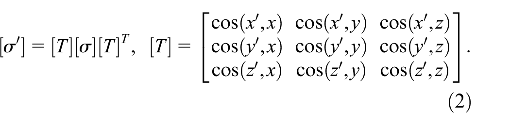
In this context,


Schematic of coordinate transformation of the stress field.
Simulation process
The research work is mainly divided into two parts: MIRS simulation and distortion simulation of the main bearing hole in the diesel engine body.
Modeling of the cutting process
The research takes a specific model of the medium-speed engine body as the research object (2553 × 1596 × 1767 mm, weighing 8.87 t), as shown in Figure 3. The machining of the main bearing hole is a critical part of marine diesel engine body manufacturing; On the one hand, the machining accuracy of the main shaft hole itself is required to be high, while on the other hand, the main spindle bearing hole serves as the machining benchmark for structures such as cylinder liner holes and camshaft holes, the residual stress significantly affects the machining accuracy of the main shaft hole. Therefore, the study focuses on the boring machining of the main spindle hole.
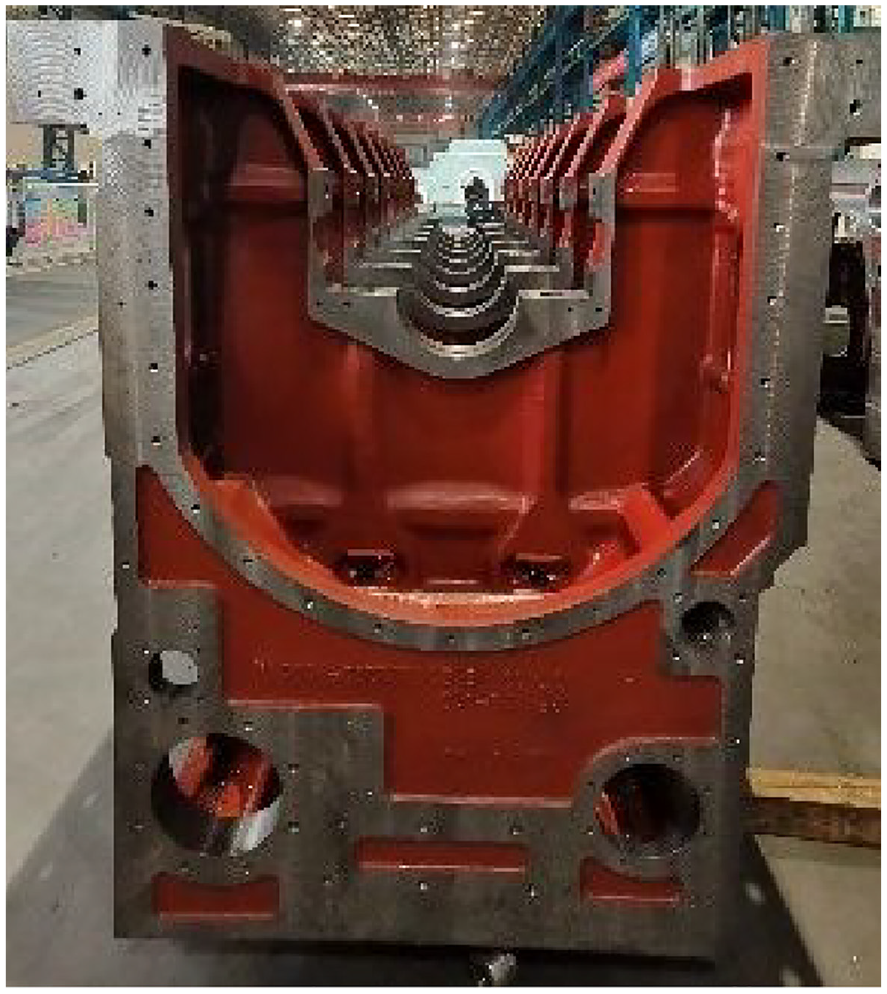
Marine diesel medium speed engine body.
The main bearing hole in the marine diesel engine body has a relatively large diameter, and referring to the simplification method proposed by Arrazola et al., 20 the AdvantEdge software’s turning module is used to simulate the boring process of the main bearing hole. First, create a three-dimensional solid model of the tool, and simplify the cutting portion at the tool’s tip, as shown in Figure 4; specific parameters are presented in Table 1. The dimensions of the workpiece’s three-dimensional model are width w = 2 mm, height h = 2.5 mm, and length L = 5 mm. In the machining simulation, the x-direction is used as the cutting direction, the y-direction is the cutting depth direction, and the z-direction is the tool feed direction. To ensure the accuracy of the calculation results, the cutting area is refined with meshing. As shown in Figure 5, the minimum and maximum mesh edge lengths for the workpiece machining surface and the tool’s cutting edge are set to 0.01 and 0.1 mm, respectively.

Tool model.
Geometric parameters of the tool.


Finite element model mesh.
The tool workpiece interaction was modeled by equation (5).
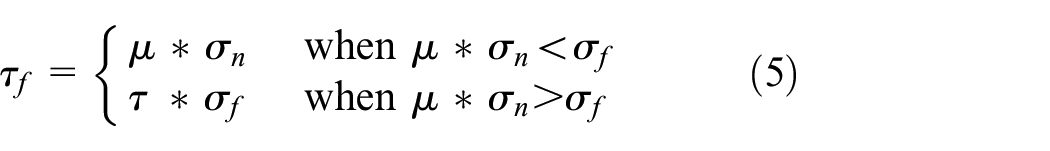
Due to the identical workpiece materials, according to Stampfer et al.’s research. 21 In this paper, the coulomb coefficient was set to μ = 0.3 and the shear coefficient to τ = 1.
The tool material is Carbide-Grade-K, and the workpiece material is QT450-12. This paper uses the Power-Law constitutive model, which can comprehensively reflect the constitutive relationship of metal materials under large strain, high strain rate, and high-temperature loading. Moreover, its form is simple and has good applicability to different material parameters. 22 The Power-Law constitutive model, as represented in equation (6), was used in this paper.

where
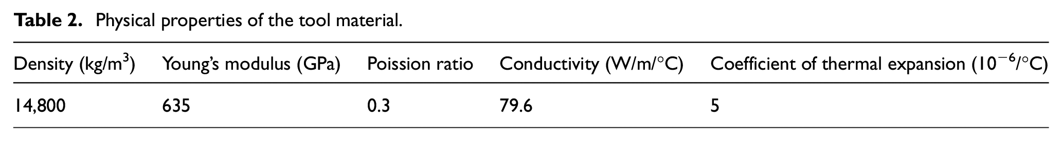
Physical properties of the tool material.
Physical properties of the QT450-12.

According to Wang et al.’s study, 23 the MIRS values along the cutting depth direction, or the Y direction shown in Figure 6, are minuscule and, therefore, can be disregarded. As shown in Figure 6, this study extracts cross-sections from three layers of the Y-X plane to ascertain the distribution in depth of MIRS orthogonal to the machined surface in the cutting and tool feed direction. It extracts data from three locations along the depth distribution on each layer. Finally, the average value of the data from each layer is calculated to derive the distribution of MIRS in depth during boring. 24

Schematic of the MIRS extraction along the depth direction of machined surface.
Modeling of machining distortion simulation
The structure of the main bearing hole is illustrated in Figure 7, with a diameter of 302 mm. The study uses ABAQUS software to simulate the machining distortion. As shown in Figure 8, the mesh thickness is refined to 0.025 mm. The main bearing hole uses a C3D8R hexahedral mesh, while the uncut areas use a C3D4 tetrahedral mesh. The local coordinate system of the unit is defined, and based on the position relationship between the local coordinate system and the global coordinate system, the conversion of residual stress from the local coordinate system to the global coordinate system is established.

Geometric model of the body.

Mesh division of the bearing hole.
In the study, all degrees of freedom of all the nodes on the top surface of the body are constrained to simulate the clamping boundary condition. To ensure the free distortion of the body due to the redistribution of MIRS when releasing the clamping boundary condition. By selecting three non-collinear nodes on the top surface of the body, whose translation freedom degrees of the directions XYZ, YZ, and Z were constrained, 25 respectively. This paper studies the impact of MIRS at a depth of 0.25 mm on machining distortion. The discrete interval of the MIRS is 0.025 mm. The SIGINI subroutine is used to transform the discrete stress values obtained from the MIRS curve and load them onto the mapping area. Assigning different stress values to elements under different numbers achieves the distribution of MIRS along different depths.
Figure 9 is a schematic diagram illustrating the loading and conversion of residual stresses using the SIGINI subroutine. The main bearing hole mesh is divided into 18 equal-spaced parts, with each section having an angle of 5°. Due to the use of C3D8R mesh, there is only one integration point, which is located at the center of the element. The angle between the integration point and the boundary element is 2.5°. In the SIGINI subroutine, the variable i represents the number of segments in the grid division of the main bearing hole, with i being equal to 18, k1 equals

Schematic of residual stress loading.
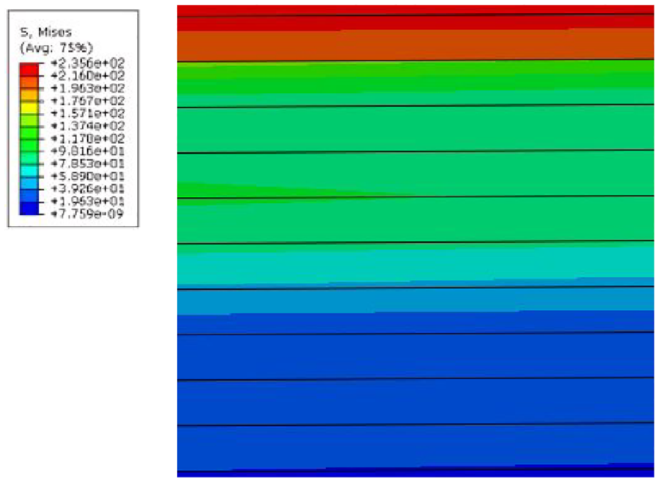
Residual stress loading result.
Unlike most thin-wall parts MIRS analysis, due to the large self-weight of the machine body, besides considering the clamping during machining, the influence of gravity load also needs to be considered. Figures 11 and 12 show the maximum distortion results without considering and considering the gravity load, respectively.

Distortion without considering gravity.

Distortion considering gravity.
Results and discussion
Analysis of MIRS
According to Dong et al.’s 24 research, when the workpiece material is Inconel 718. The material of the tool is Carbide-Grade-M. The tool has a 0.02 mm edge radius and a 1.2 mm nose radius, with a 6° clearance angle, −6° rake angle, −17.5° lead angle, and −7° inclination angle. Cutting Speed equals 55 m/min, Depth of Cut equals 0.55 mm, and Feed Rate equals 0.35 mm/r. Using the simulation method described in the previous chapter of this paper, the surface residual stress in the feed direction and cutting direction are 551 and 482 MPa, respectively. The discrepancies from the experimental results in Dong’s paper, 600 and 520 MPa, are 8% and 7%. This indicates the correctness of the simulation method proposed in this paper.
Sun et al.’s 26 research shows that cutting speed, depth of cut, and feed are essential factors affecting MIRS. This study uses the single-factor control variable method to simulate and analyze the impact of cutting speed, cutting depth, and feed rate on the distribution of MIRS in the depth direction. The cutting conditions implemented in the machining simulation are presented in Table 4.
Cutting parameters.

Figure 13(a) is the distribution of MIRS at different feeds in the cutting direction along the depth, and Figure 13(b) is the distribution of MIRS at different feeds in the feed direction along the depth. The surface residual stress (SRS) both show residual stress, transforming into compressive stress as the depth increases. When the feed increases from 0.15 to 0.30 mm/r, both the SRS and the maximum compressive residual stress (MCRS) show a growing trend, and the depth of the residual stress layer (DRSL) also increases. The depth of the maximum compressive residual stress (DMCS) in the cutting direction rises from 0.05 to 0.1 mm. DMCS in the feed direction rises from 0.04 to 0.1 mm. DRSL in the cutting direction increases from 0.17 to 0.22 mm; in the feed direction, it increases from 0.18 to 0.23 mm.

MIRS values of the simulation in depth for three different feed rates: (a) residual stress
The simulation results show that cutting heat introduces compressive plastic strain in the surface layer. Additionally, the cooling contraction of the workpiece surface forms residual tensile stress due to thermal effects on the sub-surface. The shearing force between the tool’s tip and the chip will cause shear deformation of the unprocessed surface, introducing residual compressive stress in the surface layer. An increase in cutting speed leads to an escalation in both cutting force and cutting temperature. The thermal load instigated by the cutting heat assumes a significant role, causing an increase in surface residual tensile stress. As the depth elevates, the mechanical stress brought about by the cutting force becomes increasingly prominent, thereby expanding the depth of the residual stress layer.
Figure 14(a) shows the distribution of MIRS at different depths of cuts in the cutting direction along the depth, and Figure 14(b) shows the distribution of MIRS at different depths of cuts in the feed direction along the depth. The SRS shows tensile stress as the depth increases, transforming into compressive stress on the sub-surface. As the depth of cut (DOC) expands from 0.1 to 0.3 mm, both the SRS and the MCRS exhibit an upward trend. Simultaneously, the DRSL also rises. DRSL in the cutting direction augments from 0.17 to 0.25 mm; in the feed direction, it enlarges from 0.19 to 0.25 mm.
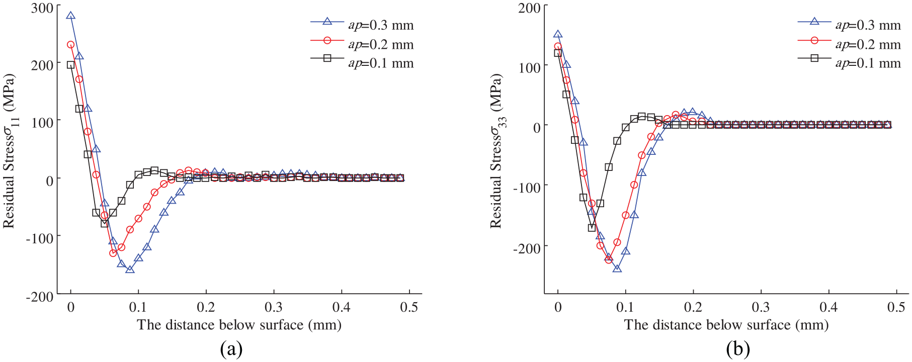
MIRS values of the simulation in depth for three different depths of cut: (a) residual stress
The increase in the DRSL is more significant compared to the feed. This can be attributed to the fact that the impact of the depth of cut on the cutting force is more significant than that of the feed rate. As the depth of cut escalates, the consequential mechanical stress, driven by the cutting force, markedly intensifies, thus substantially augmenting the depth of the residual stress layer.
Figure 15(a) displays the MIRS distribution at different cutting speeds in the cutting direction. Moreover, Figure 15(b) demonstrates the MIRS distribution at various cutting speeds in the feed direction. SRS exhibits tensile stress, converting into compressive stress on the sub-surface as the depth increases. In the cutting direction, the DMCS is 0.05 mm. In the feed direction, the DMCS is 0.04 mm. As the cutting speed escalates from 80 to 150 m/min, both the SRS and the MCRS exhibit an upward trend, but the increase in the DRSL is negligible. This can be attributed to the fact that the impact of cutting speed on cutting force is minimal. Consequently, the mechanical stress alterations resulting from an amplified cutting force due to increased boring speed are insignificant. Thus, the depth of the residual stress layer essentially remains stable.

MIRS values of the simulation in depth for three different cutting speeds: (a) residual stress
Analysis of the machining deformation
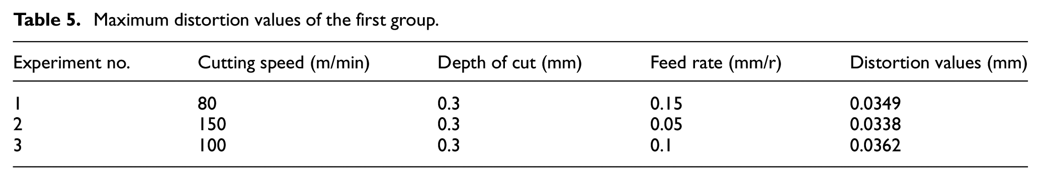
This study explores the influence of various wall thicknesses on the machining distortion of the main bearing hole. Two groups are under consideration: the first features a radial thickness of 37 mm, and the second has a radial thickness of 46 mm. The residual stress is applied to the workpiece along the thickness direction. Upon the release of clamping boundary conditions, the body undergoes distortion, a process that also takes the effect of gravity load into account. The maximum distortion data, sourced from nodes located on the surface of the main bearing hole, are documented in Tables 5 and 6.
Maximum distortion values of the first group.
Maximum distortion values of the second group.

The maximum distortion of the first, second, and third experimental groups exceeds the allowable tolerance value of
When the wall thickness is minimized to 46 mm, the machining distortion complies with the machining requirements.
Through a practical investigation of the factory, 30 sets of processing data for the main bearing holes of shipborne diesel engines were obtained from the factory. Among them, 25 sets of the main bearing hole processing deformation were 0.02 mm, three sets of the main bearing hole processing deformation were 0.03 mm, and one set of the main bearing hole processing deformation was 0.01 mm. Actual production shows that when the cutting speed is 80 m/min, the cutting feed rate is 0.15 mm/r, and the cutting depth is 0.3 mm, the maximum machining distortion of the main bearing hole is 0.02 mm. This observation is aligned with the simulation result of the eighth group, thereby verifying the accuracy of the simulation results. The simulation further elucidate that the larger the minimum wall thickness of the main bearing hole, the better the rigidity and the stronger the ability to resist deformation.
Figure 16(a) illustrates the variation in the maximum distortion of the main bearing hole, as determined by simulations at different feed rates while keeping a cutting speed of 80 m/min and a depth of cut of 0.3 mm constant. The maximum deformation escalates from 0.0113 to 0.0189 mm as the feed rate increases from 0.05 to 0.15 mm/r. It demonstrates an increase in deformation of the main spindle hole with the increment in feed rate.

Variation of the maximum distortion with different cutting parameters: (a) Scheme 1, (b) Scheme 2, and (c) Scheme 3.
Figure 16(b) depicts the variation in the maximum distortion of the main spindle hole, as determined by simulations at different cutting depths while keeping a constant cutting speed of 80 m/min and a feed rate of 0.3 mm/r. The maximum deformation increases from 0.0171 to 0.0191 mm as the depth of cut elevates from 0.1 to 0.3 mm. Once again, an increase in the depth of cut corresponds to an increase in the deformation of the main bearing hole.
Figure 16(c) represents the variation in the maximum distortion of the main bearing hole, simulated at different cutting speeds while maintaining a cutting depth of 0.3 mm and a feed rate of 0.3 mm/r constant. The maximum deformation escalates from 0.0113 to 0.0174 mm as the cutting speed amplifies from 80 to 150 m/min. Consistent with the previous results, an increase in the cutting speed leads to an increase in the deformation of the main bearing hole.
Simulation results suggest that the machining distortion in the main bearing hole in Experiment 1 is more substantial than that in Experiment 5. The amplitude of both the SRS and the MCRS in Experiment 1 is more significant than in Experiment 5; DRSL in both experiments is similar. Consequently, the magnitude of the distortion is predominantly influenced by the distribution of MIRS. A higher amplitude of SRS and MCRS tends to amplify the machining distortion, whereas the DRSL has a minor effect on the distortion of the main bearing hole.
Conclusion
(1) Marine diesel engine bodies are characterized by their substantial size and self-weight, leading to a considerable divergence between traditional methods of researching the distortion of MIRS and the actual conditions. Research findings indicate that the coupled relationship between MIRS and the component’s self-weight should be considered when analyzing the machining distortion of large-sized, thin-walled structures.
(2) The depth of the residual stress layer is closely tied to the cutting parameters. Of these parameters, cutting depth exerts the most significant influence on the depth of the residual stress layer, followed by the feed rate. Meanwhile, the cutting speed has negligible influence on the DRSL. The cutting speed, feed rate, and depth of cut are positively correlated with the machining distortion and the surface residual stress.
(3) Enhancing the rigidity of the workpiece and increasing wall thickness can effectively diminish the distortion instigated by MIRS. By optimizing the wall thickness, it is not only possible to confine the range of distortion but also to support the lightweight design of the structure, ultimately leading to structural optimization.
Footnotes
Handling Editor: Chenhui Liang
Declaration of conflicting interests
The author(s) declared no potential conflicts of interest with respect to the research, authorship, and/or publication of this article.
Funding
The author(s) received no financial support for the research, authorship, and/or publication of this article.