
Abstract
A weak-rigid monolithic component is subjected to significant distortion after the removal of material. This condition is principally due to flexibility of the part and the release of initial residual stresses resulting from fabrication. This article reports a systematic study on the measurement of initial residual stresses and the distortion of a windshield frame part induced by material removal from the forged blanks of aluminum alloy 7085-T7452. A layer-removal method was employed to measure the stress profiles of the blank. The stresses after analytical correction were found to be closer to actual condition. The effect of material removal on distortion from stressed blank was investigated using the finite element analysis software ANSYS. The simulated results indicate that after the proportion of removed material exceeds 60%, part distortion becomes stable. The comparisons of the simulation with experimental data suggest sufficient agreement with conclusion that the use of finite element analysis proves to be an attractive and reliable method for predicting stress-induced distortion.
Introduction
Monolithic components are widely applied in aerospace industry to reduce assembly time or cost and to improve component performance. Machining is an essential step in the manufacturing of these components. Owing to large dimension, thin wall, low rigidity and large amount of removed material, 1 they are prone to distorting after machining. Statistics shows that the distortion applied to low-rigidity components accounts for 47% chance of causing a nonconformity in dimensional or geometrical tolerances. 2 These problems result in high scrap and rework costs. 3
Blanks from which the parts or components are machined had already undergone forming operations and treatments such as forging, quenching, and extrusions which are combined with heat transfer, mechanical deformation and metallurgical changes. 4 The combination introduces residual stresses in the material. The release and redistribution of the residual stresses are the main reasons for the machining distortion, even if the magnitude is relatively low. Brinksmeier et al. 5 reported that initial residual stresses had continuous distribution in the axial and transverse directions along the thickness. These stresses resulted in self-balance and protected workpiece from distortion. When a section of workpiece containing residual stresses was machined as allowance, a new static equilibrium of residual stresses and moments in the remaining material would be achieved, which caused another self-balance for workpiece. The redistribution of these residual stresses led to changes in the shape and dimensions of the part.
To analyze the distortion of parts induced by residual stresses, an estimation of residual stress fields within the blank should be carried out first. Current residual stress measurement techniques are generally divided into two groups: 6 nondestructive methods and destructive ones. The X-ray diffraction is a key method in measuring stresses within microscopic scale. However, this approach is commonly restricted to the surface or subsurface due to the poor penetration level of X-ray beams.7,8 Thus, the present techniques for measuring stress variations through the whole cross section of specimen are limited to destructive methods. Among these techniques, compliance method and layer-removal method are effective ways to obtain the distribution of the residual stresses through the thickness of workpieces. The crack compliance method involves cutting a small slot to monitor the relaxation of stresses in the vicinity of the crack using strain gages interferometry. 9 By steadily increasing the depth of the slot, it is possible to resolve the stresses field normal to the crack as a function of depth for relatively simple stress distribution. 10 As a typical destructive measurement technique, the layer-removal method is an effective way to obtain the profile of residual stress. Mahmoodi et al. 11 studied the determination of residual stress magnitude and distribution in a 2-mm-thick sheet of aluminum alloy 5083 by utilizing layer-removal and X-ray diffraction methods. Guo et al. 12 developed a modified layer-removal method in which a strain gage was placed on one surface of the workpiece and layers were removed from the other side. However, the experimental results exhibited errors greater than 100% on the surface, and errors greater than 200% for the maximum compressive and tensile stresses when compared with actual residual stress levels. 13 As the stressed material was removed, the remaining stresses would change and redistribute. 14 Therefore, the measured subsurface residual stresses are necessary to be corrected.
As assumed that the release and redistribution of the initial stresses within raw material induced by the blank making processes are the major reasons of part distortion, the study of effects of residual stress distribution and magnitude on machining distortion of monolithic parts or components is essential for the research on optimization of process plan. There exists an optimal amount of removed material according to initial residual stresses. When the amount of the material removal is set to the optimal value, the machining deformation could be controlled effectively. 15 The experimental approach to study machining deformation is usually expensive and time-consuming. Therefore, the prediction and analysis of the deformation due to initial residual stresses within the blank using numerical simulation could offer a fast and economical alternative.
In this article, an aircraft windshield machined from high-strength wrought aluminum alloy 7085-T7452 is embedded with complicated residual stresses due to forming processes of hand forging and heat treatment. The forging residual stresses within a blank of aluminum alloy 7085-T7452 are evaluated by the layer-removal method. The machining distortion of the aircraft windshield due to the release and redistribution of residual stresses is predicted using the finite element method (FEM). The optimal amount of removed material can be proposed for machining distortion control. Finally, the prediction of the final distortion is compared with experimental data to establish confidence in the simulation process.
Theoretical analysis for measurement of residual stresses
Measurement method
In this article, prediction of the part distortion only concerns the influence of redistribution of residual stresses caused by the removed material. The forging residual stresses can be experimentally determined using layer-removal method. For the layer-removal technique, there are some assumptions about the stress fields of the specimen to be measured.
16
The distribution can be assumed biaxial in the plane of the sample and varies through the thickness. In addition, stresses in each layer are uniform. The techniques of layer-removal method for measuring stress variations through the full thickness of a blank are currently limited to destructive method, which can be explained as follows:
17
a small square island is labeled on the center of the top surface of the workpiece to be measured (see Figure 1). Then, the strain gage is glued on the top region of the square island. When the surrounding material is removed, the changes of residual stress are reflected by the strain variations. The relationship between measured strains and corresponding released stresses is expressed in equation (1). The biaxial stresses
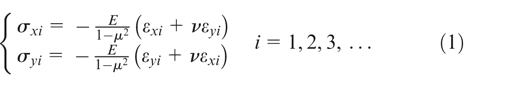
where
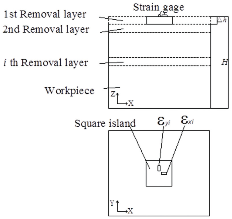
Schematic diagram of the layer-removal method for residual stress measurement.
Residual stress correction
As mentioned before, when several layers of material are removed, the magnitude and distribution of stresses in the remaining material are changed to keep a new state of self-balance. Therefore, in order to determine the original residual stresses in material produced by the forming process such as extrusion, rolling and forging, the measured stresses of specimen are necessary to be corrected.
The measured stresses are defined as variables of
Given the total thickness H, the specimen is sliced into n layers along the z direction with thickness t for each layer. After the total i layers of material from the top surface are removed, bending–stretch deformation occurs in the remaining material. The strains of the first layer in remaining specimen after i layer removal arise from the interaction of each layer removed respectively. Derived from the elastic mechanics, the relation between removed layers and top layer of remaining material is expressed as
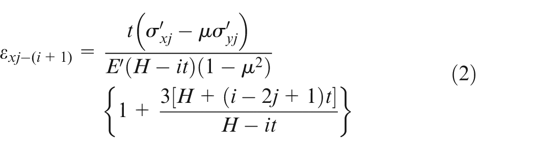
where jth layer is one of the i removed layers, (i + 1)th layer is the top layer of the remaining material and

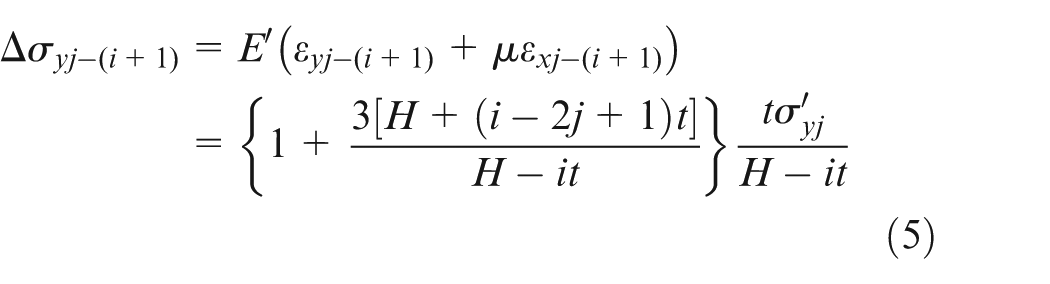
The cumulative values of additional stresses in the (i + 1)th layer are computed as

Finally, the initial stresses of the (i + 1)th layer are obtained through


where
Experimental measurement of initial residual stresses in blank
Overview of the blank and part
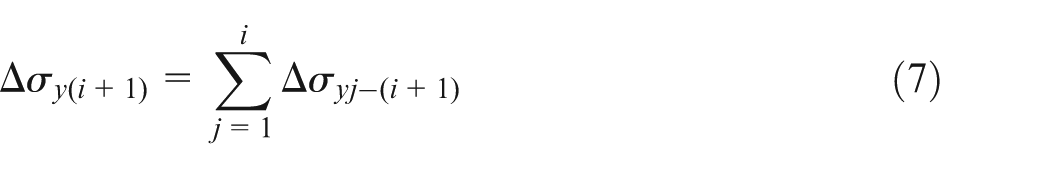
The material property of the workpiece is high-strength aluminum alloy 7085-T7452 with Young’s modulus of 71 GPa and Poisson’s ratio of 0.33. 7085-T7452 is a new specification for aluminum alloy. The forging blank is prepared with nominal thickness of 12 in (305 mm). These forgings are used typically in structural parts requiring high strength and resistance to stress–corrosion cracking. The blank of aluminum alloy 7085-T7452 is produced through sequential processes, including forging, solution heat treatment, and T7452 stress relief operation. 18 Figure 2 shows the blank and part. The dimension of the blank is 2161 mm×1534 mm×163.5 mm with arc radius of 305 mm. The windshield frame part, a typically monolithic part used in aerospace industry, is machined through milling by removing 87% of the material from the blank.
Blank and part.
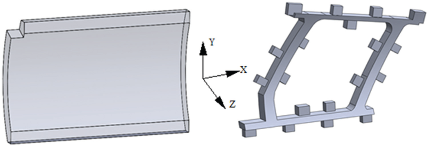
As shown in Figure 2, the blank is quite large in dimension with weight of over 1.5 ton. Apparently, it seems impossible to perform the measurement of residual stress in such a large-sized blank. Therefore, five small specimens with cubic shape are taken from the extra portion of the original blank. Each specimen is similar in geometry with a dimension of 150 mm×150 mm×135 mm. The locations of five specimens Y1–Y5 in the blank for test are marked in Figure 3.
Locations of the five tested specimens.
Measurement of residual stresses
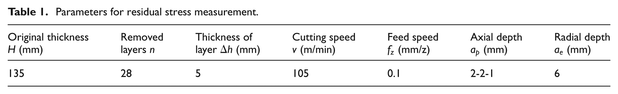
During the experimental measurement of residual stresses, one strain gage was placed on the top surface of the specimen as presented by layer-removal method, and the layers were removed by milling on an XK7132 computer numerical control (CNC) milling machine. Table 1 lists the parameters for the measurement. In order to reduce the influence of residual stresses induced by machining process, operation of removing a layer of material was completed through three cuts, first two of the thicknesses of 2 mm and last cut of thickness of 1 mm. Figure 4 illustrates the experimental process.
Parameters for residual stress measurement.
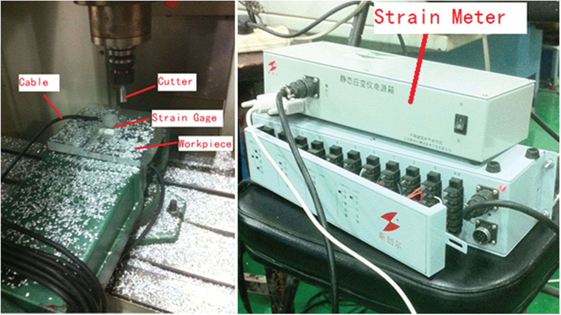
Process of measuring residual stresses.
Correction of initial residual stresses in measured specimens
After each layer is removed from the top surface of the specimen, the changes in strain readings are observed. Substituting these strain readings into equation (1), respectively, the two groups of released stresses
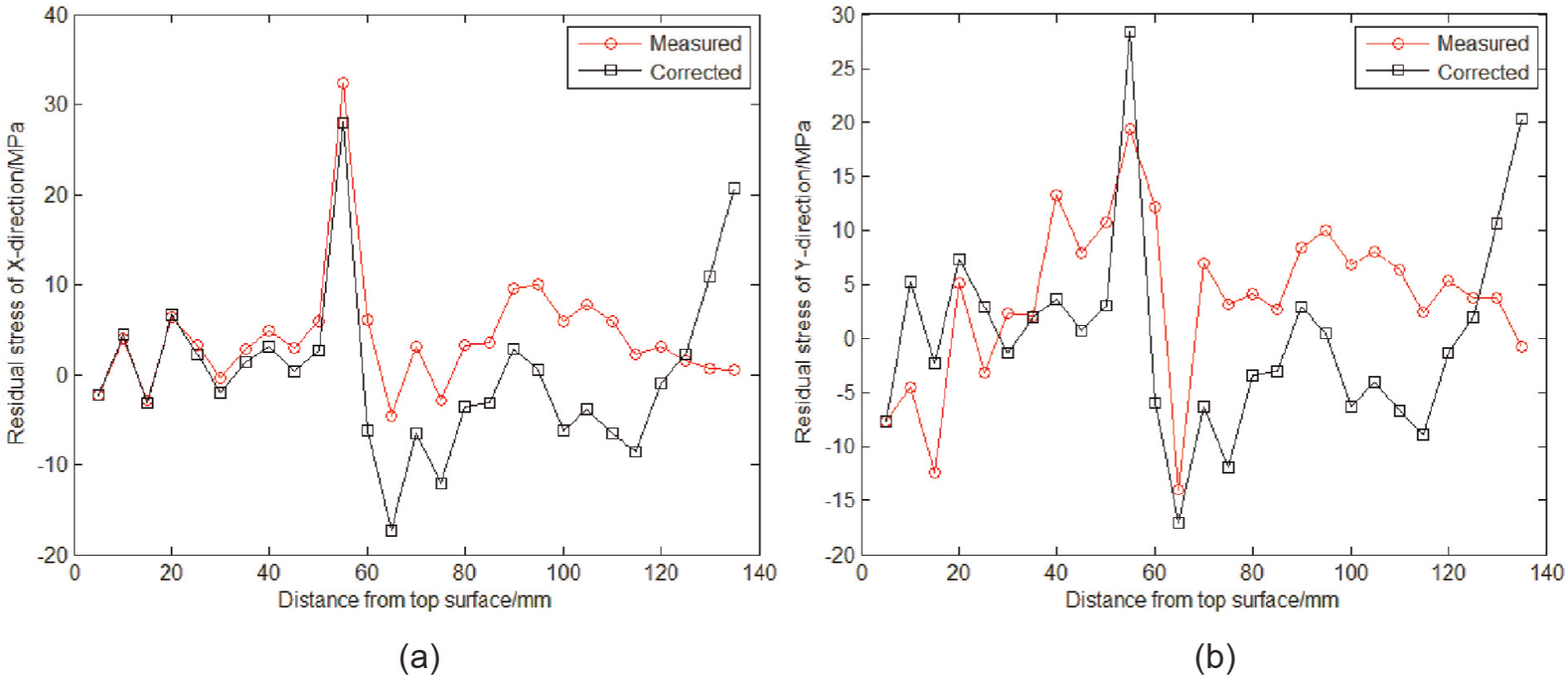
Correction values of residual stresses for specimen Y1: (a) x direction and (b) y direction.
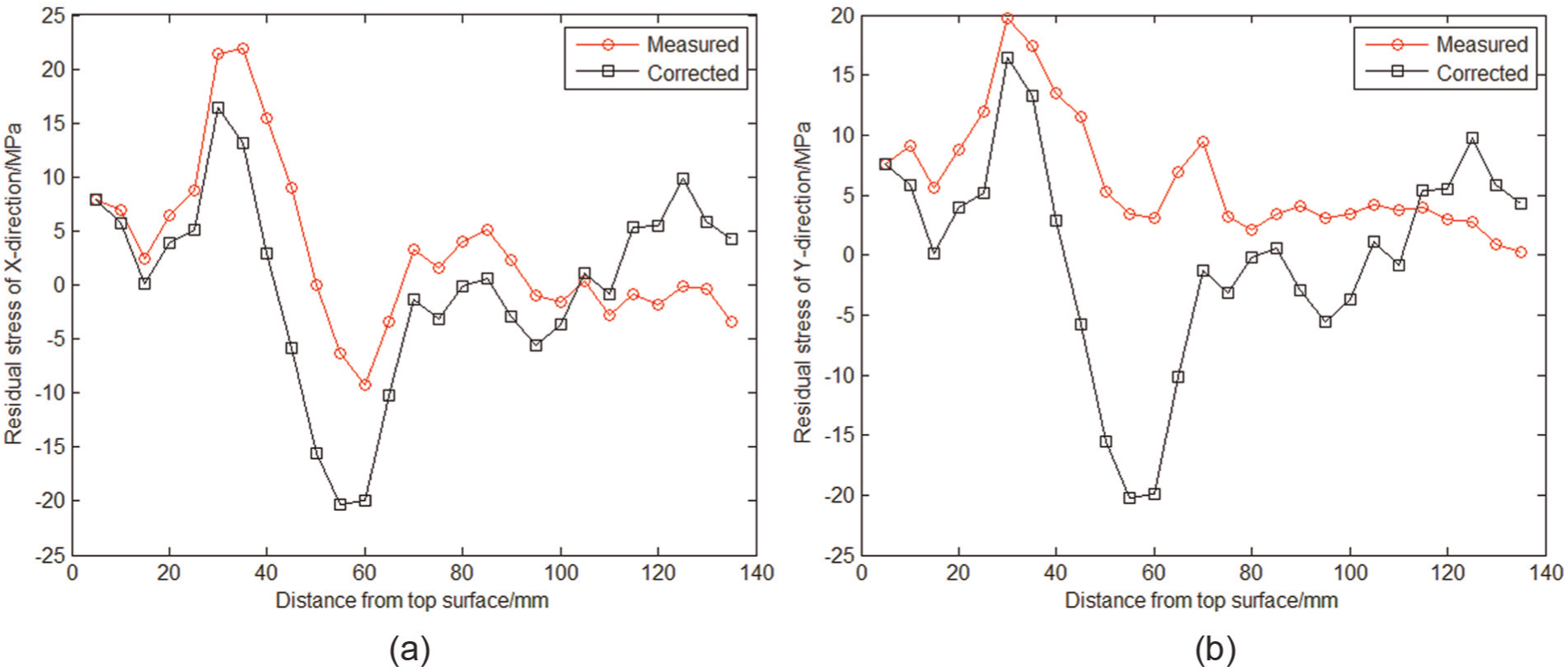
Correction values of residual stresses for specimen Y3: (a) x direction and (b) y direction.
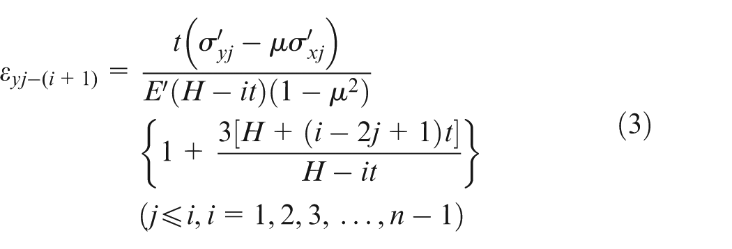
The profile of residual stresses in the x direction through the thickness is similar to that in the y direction for both initially measured and corrected data. It should be noted that when residual stresses are released from materials by the layer-removal technique, the internal stresses must redistribute to be balanced. Equation (3) expresses the stress equilibrium over the thickness of the specimen.
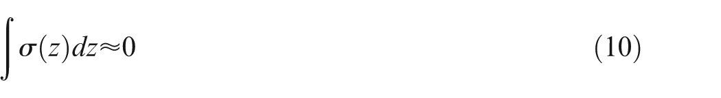
where
Substituting experimentally measured and corrected stresses for specimens Y1 and Y3 illustrated by Figures 5 and 6 into equation (3), the initial residual stresses are found to be closer to zero. It indicates that the stresses after correction are more subject to balanced condition than that before correction, as listed in Table 2. In the subsequent prediction of part distortion, the initial residual stresses are to be used as input parameters.
Results of algebraic sum of residual stresses through thickness (MPa).
Modeling and simulation of machining distortion
The finite element (FE) simulation can aid understanding the deviation of the part from nominal geometry through machining process and promise significant time and cost savings. As analyzed previously, only the release and redistribution of residual stresses within the blank are taken into consideration, eliminating effects from clamping, cutting force and heat.
FE-based model of the blank
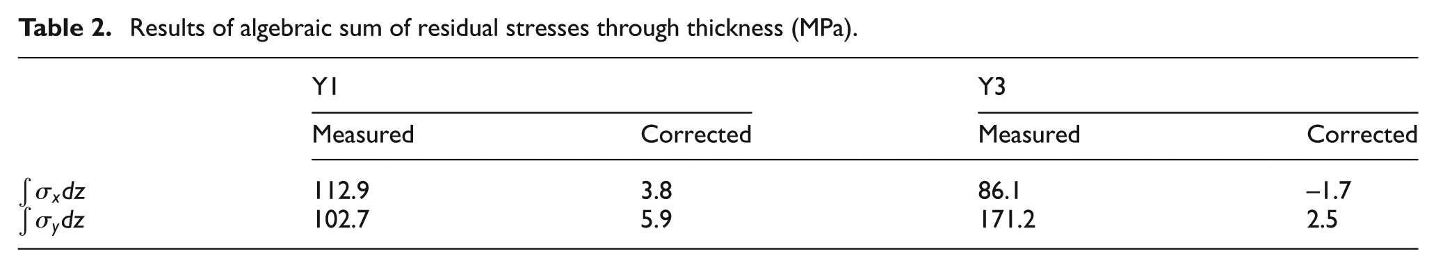
Based on the data of initial stresses in the specimens Y1–Y5 after correction of measured stresses, initial stresses in sections excluding the five blocks can be derived on the principle of linear interpolation. In the simulation model, residual stresses in each layer are applied to the corresponding elements by writing program codes. A FE model of the blank with overall profiles of initial residual stresses is built in ANSYS, as shown in Figure 7.
FE model of the blank: (a) residual stresses for the x direction and (b) residual stresses for the y direction.
Boundary conditions
In this simulation model, three noncollinear points on the bottom surface are selected and their x, y, z degrees of freedom (DOFs), y, z DOFs and z DOF are constrained, respectively. This approach ensures that after the machining is finished and clamping fixtures are unloaded, the part can deform freely due to the redistribution of residual stresses.
Simulation of machining process
In the simulation, the blank material is removed layer by layer with thickness of 30 mm for each layer. Machining process is organized in sequence as follows: material in the core of the blank was first cut and then outside.
The removal of material in FEM is realized by death concept. The stiffness matrices of the elements are set close to zero, which leads to killing the elements, hence representing the material being removed. In addition, load vectors related to killed elements are also set to zero. With elements killed layer by layer, material is gradually removed away from the blank, and the rigidity of the remaining workpiece is reduced. The initial equilibrium state of stresses is broken to establish a new state of self-balance due to the release and redistribution of residual stresses, which produces the part distortion.
Simulation results and discussion
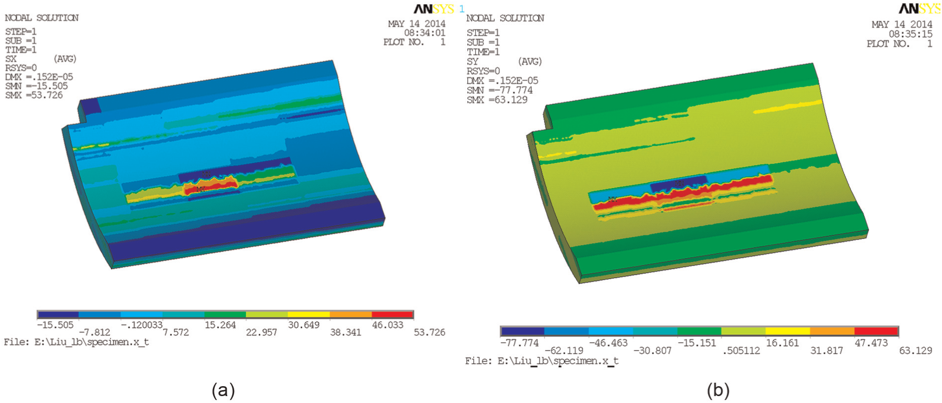
Figure 8(a)–(d) presents overall deformation of the part after several layers are removed, which provide beneficial information in studying the effect of various amount of material removed on the distortion.
Part deformation during material removal: (a) deformation after material inside the blank is removed, (b) deformation after the first layer is removed, (c) deformation after the fourth layer is removed and (d) final deformation.
To further investigate the influence of removed material on deformation, a small region labeled as “A” representing reference plane in the part is chosen as shown in Figure 8(d). Figure 9 presents the deformation of this location after each layer is removed. It can be seen from this figure that at the beginning of the material removal, the deformation gradually increases as more material is cut away. When the third layer is removed, or the proportion of removed material is 37%, the deformation reaches a maximum value of 1.87 mm. Then, the deformation drops rapidly from third to fifth layer. After 60% of the material is removed, the deformation varies slightly. Therefore, it could be concluded that further control strategies on machining deformation can be applied to parts after this percent of removed material.
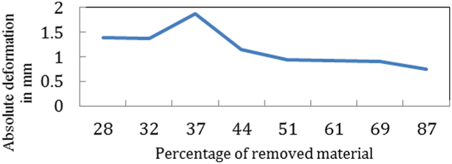
Deformation of point “A” varying with the amount of removed material.
The reason for the decreasing distortion after about half of the material is cut away is to be discussed in the following section. For the aluminum alloy 7085-T7452, the surface is more likely to hold tensile stresses while the inner part has compressive stresses as shown by experimental results in Figure 6. As illustrated in Figures 10 and 11, when the first few layers are removed from the top surface, the stress distribution alters dramatically in remaining material which leads to asymmetrical tensile stress distribution on top and bottom surfaces. The FE simulation results show that after a 30-mm-thick layer is removed, stresses in the x direction on surface of specimen Y3 change into compressive stresses and the magnitude becomes smaller as shown in Figure 10. This asymmetrical stresses cause both ends of the blank to deflect. As the machining process continues, stresses in the remaining blank adjust automatically to achieve another balanced state. 20 Figure 11 illustrates residual stress profile of the x direction in specimen Y3 after 60-mm-thick material is cut away. The algebraic sum of both tensile and compressive stresses close to zero explains the reduction of deformation shown in Figure 9. After the machining process is finished, most residual stresses are released and the distortion of specimen decreases to a relatively low level.
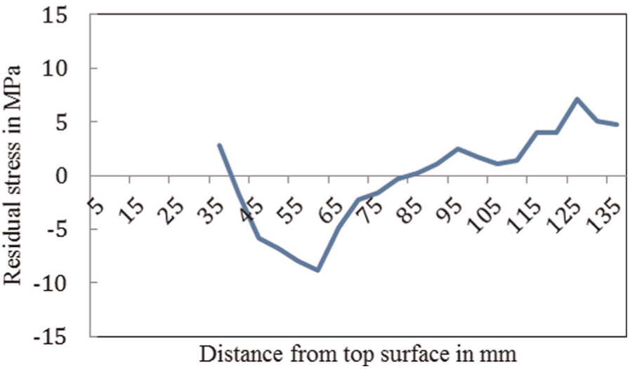
Residual stress distribution after removing 30-mm material.
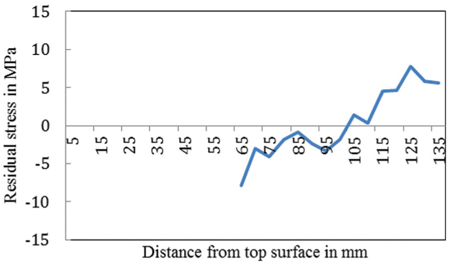
Residual stress distribution after removing 60-mm material.
Experimental verification
To verify the simulation results, the designed part is machined on a CNC machining center presented in Figure 12. The spindle speed is 18,000 r/min with the axial depth of 0.5 mm and the feed speed of 4000 mm/min. The final distortion of the part is measured by a surface measurement device along the four sections in corners of the part as illustrated in Figure 13.
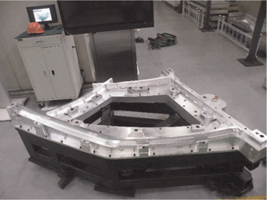
Machined part.
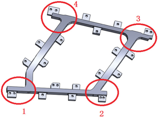
Sections for measuring distortion.
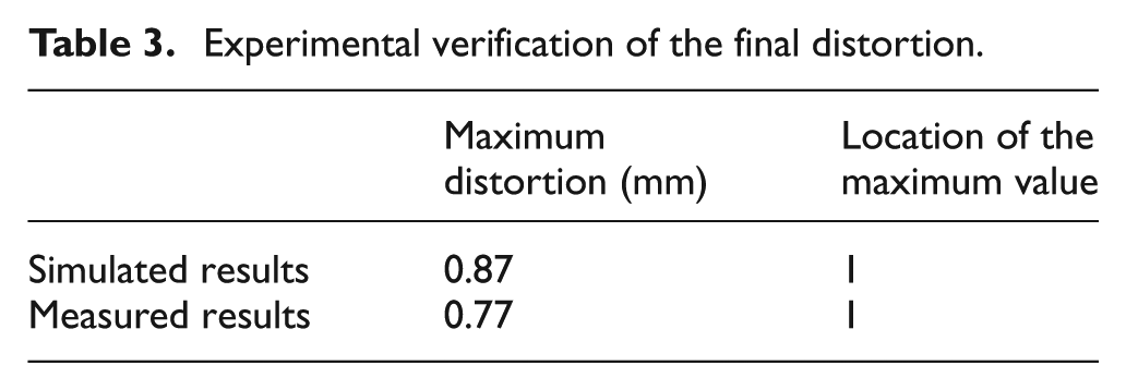
Table 3 shows the maximum values of the final distortion and their locations in both simulation and experiment. It can be seen that the difference between the predicted and experimental deviation is 0.1 mm or less than 11% and both occur in section 1. The FE simulation and measurement present very similar distortion in terms of magnitude and location. Since the simulation is processed under the assumption of neglecting cutting heat, cutting force and tool vibration, the relative errors are inevitable in the comparison.
Experimental verification of the final distortion.
Conclusion
With the objective of predicting the distortion of windshield frame part due to residual stresses, the profile of residual stresses in aluminum alloy 7085-T7452 blank produced from forging process was measured by a layer-removal method. The initial residual stresses throughout thickness are obtained based on the experimental ones combined with the theory of elastic mechanics. By analyzing algebraic sum of the two groups of residual stresses in the x and y directions, corrected stresses are close to 0 while that of measured is over 100. The data after correction are more accurate than initially measured ones.
A prediction model of machining distortion considering residual stresses was built. The residual stresses in blank vary with material removal, resulting in part distortion. The largest displacement from the nominal shape occurs in section 1. After about half of the material is removed, the stresses are redistributed to a balanced condition which reduces the deviation gradually. When the proportion of removed material reaches 60%, the deformation becomes stable. Further control strategies to solve machining distortion can be applied to the part after this state.
Experiment was conducted to verify the simulation results. The maximum value of final distortion in experiment is 0.1 mm less than that in simulation, and both occur in the same region. Thus, the use of FE analysis proves to be an attractive and reliable method for predicting stress-induced distortion.
Footnotes
Appendix 1
Declaration of conflicting interests
The authors declare that there is no conflict of interest.
Funding
This work was financially supported by the National Science and Technology Major Project (2014ZX04001011).