
Abstract
Solution-treated AA 6061 alloy contains residual stresses which cause unwanted deformation during the machining operation rendering the parts unacceptable for use. Usually for AA 6061 alloy, stress relieving is performed by re-heating the parts at 343°C for 1 h. This stress relieving is however accompanied by a considerable loss of material strength which subsequently reduces the functionality of the parts. This paper is based on an effort to evaluate the effectiveness of lower re-heating temperatures for stress relieving without significant loss of strength. Temperatures within the range of 200–343°C were used and treated samples were tested for both the strength and machining distortion. The experimental results indicate 60% reduction in machining distortions with 21% decrease in the strength.
Keywords
Introduction
Aluminium 6061 is a widely used alloy due to its light weight, high structural strength, good corrosion resistance and weldability. Lee and Tang 1 investigated the mechanical behaviour of 6061 alloy in T6 temper at high strain rates and found it to possess considerable potential for thermo-mechanical forming without failure. However, these favourable properties of T6 temper are attained via the solution treatment process which involves high temperature heating and rapid cooling of material resulting in residual stresses.
Dolan and Robinson 2 identified that the temperature gradient produced across the material during faster cooling is the main cause of residual stress. This gradient causes different areas of the material to cool differently resulting in non-uniform contraction which puts some areas in tension balanced by others in compression. This state of residual stress presents serious problems during the machining operation wherein the stresses are released in the form of unwanted deformations making the part unacceptable for use. It has been proposed to use a combination of cooling rates during the solution treatment. For every material, there is a critical range of temperature where a little time is sufficient to cause significant premature precipitation. The material should therefore be rapidly cooled within this range. Other than that a slower cooling may be employed to reduce the total thermal gradient. The critical range of an alloy is determined using its TTP (time–temperature property) curve. Fink and Willey 3 are one of the first researchers to develop TTP curves for aluminium alloys. Some of the latest work includes that of Li et al. 4 who studied the quench sensitivity of 6000 series aluminium alloys by developing TTP curves through interrupted quenching technique. Dean and Croucher 5 employed a technique called up-hill quenching where the parts, after solution treatment, are exposed to freezing temperatures using liquefied gas. The parts are then heated using boiling water or steam to produce an opposite temperature gradient that counters the previous stresses of solution treatment. Lim et al. 6 reported 91% reduction in residual stresses through up-hill quenching. However, both the up-hill quenching and the critical range technique require the control of solution treatment which is not available for parts that are treated at supplier's end.
For pre-treated parts a more conventional and simpler technique of re-heating is available. The problem is that re-heating besides stress relieving also reduces the material's necessary strength. The objective of this research is therefore to identify a low temperature re-heating that relieves the residual stresses without significant loss of strength.
The reason for reduction in strength after re-heating is the motivation for semi-coherent β″ precipitates to acquire a more stable β′ phase due to increased atomic diffusion. These precipitates now have lesser contribution in strengthening. If the heating further continues the precipitates turn in to a fully distinct β phase which has no coherency with the base structure. This distinct phase is unable to arrest the dislocations and only presents physical hindrance to their movement. The material in this condition is said to be overaged and shows inferior strength. Re-heating at highly elevated temperatures, as experienced during welding, can even dissolve back the secondary precipitates available for strengthening.7–11
Maisonnette et al. 12 studied the coarsening of secondary precipitates with re-heating and identified an average increase in precipitate length and diameter by more than 250 and 64%, respectively after re-heating at 400°C. A strength reduction of about 60% was also observed after re-heating at 450°C compared to the original T6 state. Lee and Tang 1 reported similar influence of re-heating on AA 6061 alloy. They found re-heating to increase the size of dislocation cells while reducing their number and distribution across the base matrix. This caused the alloy to soften and the flow stress required to continue material deformation at a given strain rate decreased. They identified an average drop in flow stresses by 9.3% when the exposed temperature increased from 100 to 200°C while a further decrease of 16% was recorded at temperatures up to 350°C.
Agarwal et al. 13 found that the secondary precipitates are brittle compared to the base structure and give rise to localised cracks at high loads. These cracks later grow in to voids which play a major part in failure mechanism of AA 6061 alloy. Gharavi et al. 14 identified that the electrochemical potency of these precipitates with respect to the base matrix poses the susceptibility of localised corrosion. De Hass and De Hosson 15 investigated the grain boundary segregation of these precipitates and related it with inter-granular corrosion, a precursor to stress corrosion cracking. All of these studies show the negative consequences of over-precipitation which further affirms the need to keep the re-heating temperature as low as possible for better properties.
Besides the residual stresses induced by thermal gradient the machining induced stresses also take part in material distortions. These stresses are a function of machining parameters, tool and part geometry and the material's inherent properties. Huang et al. 16 found that the effect of machining stresses is greater in thin sections. A sample with a final machined thickness of 0.75 mm deformed approximately 9.8 times that of the 1.75 mm sample. Denkena et al. 17 found that higher cutting speeds lower the final distortions in thin sections. Sridhar and Ramesh Babu 18 investigated the effect of cutting tool dia. on machining distortions. The distortions were found to increase by 41.6% when the cutting tool dia. increased from 6 to 16 mm.
Since the domain of this study does not include optimisation of machining parameters the experimental variables are purely related to the re-heating treatment. Different temperatures of re-heating were used keeping the machining parameters and sample geometry as constant. Tests were performed for both the machining distortion and material strength to identify the re-heating temperature that provides the best balance between stress reduction and strength preservation.
Experimental work
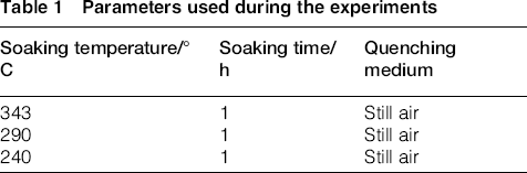
Parameters used during the experiments
Mechanical testing
Samples for tensile testing were prepared from a stock piece of raw material as per the ASTM-E8 (Sheet Type) standard. Rough blanks were extracted from the raw material blocks through bend saw machining. It was ensured that all the samples are from the same material orientation to avoid variation of properties. The blanks were than milled to final dimensions of 200 × 20 × 10 mm. A dog-bone profile was then prepared with a gauge length of 50 mm. Coolants were used throughout the machining process to minimise the addition of unwanted heat. The samples were tested on a Tinius Olsen H150KU universal testing machine with an Epsilon extensometer attached to measure the elongation before failure. A 0.2% offset method was used to evaluate the yield strength in each tensile test.
The hardness tests were performed on samples extracted from the same blocks as the tensile samples. The testing was performed as per ASTM-E92 (Vicker's) standard on an Ernst bench-type tester.
Machining test
The machining test was performed to determine the reduction of machining distortion after re-heating at each of the three selected temperatures. The starting thickness of the samples was kept at 12 mm to avoid any premature distortion. The rectangular shape was selected for the samples due to its ease of preparation from a sheet stock. The length of the samples was kept as much as five times the width in order to mimic a thin long overhang part for prominent effect of distortion.
The samples were re-heated at the three selected temperatures and machining was performed to reduce the thickness up to 2 mm. At this small thickness, the material strength was easily superseded by the residual stresses resulting in distortions. These distortions were then used to relate the effectiveness of each re-heating temperature. As a reference, the pre-machining distortion of each sample was measured using a coordinate measuring machine. Several readings were made for the sample thickness against a flat base using the machine probe and the thickness was found to vary in the range of 5–20 μm. Hence all of the samples were initially flat to reasonable extent.
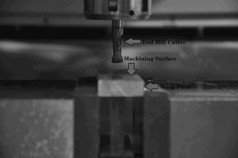
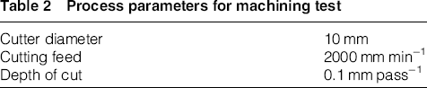
The machining of the samples was performed using a CNC milling machine with a solid end mill cuter. The machining parameters, as given in Table 2, were selected to avoid large induced stresses. All the samples were clamped from the base using a vice and material was gradually removed from the top side. The machining setup is shown in Figs. 1 and 2.
Clamping setup for machining Cutting tool and the workpiece Process parameters for machining test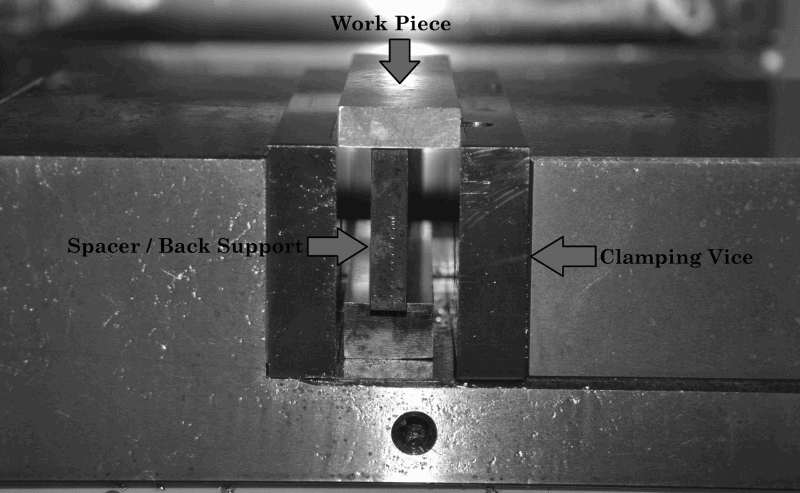
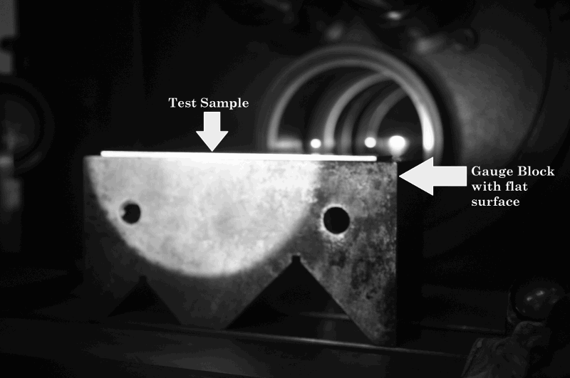
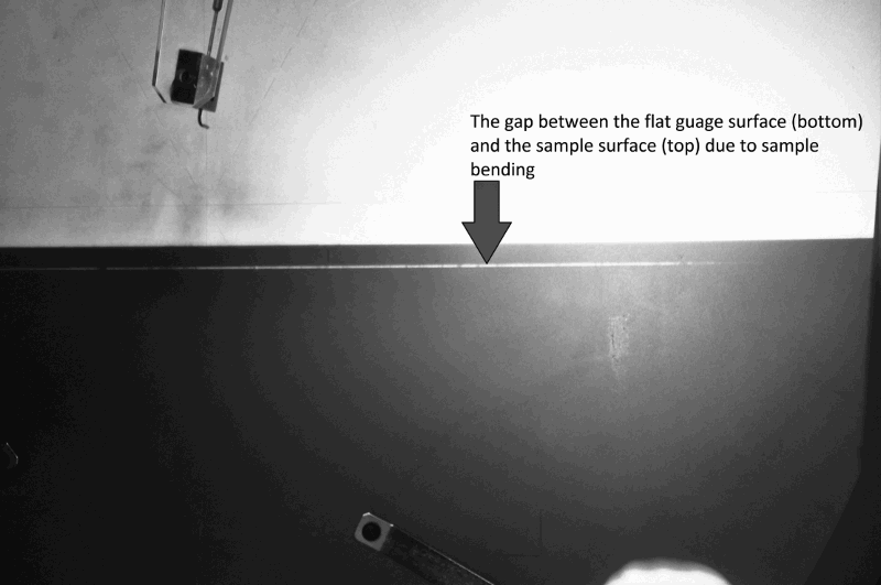
For the after machining distortions, the samples were examined on a Starrett Sigma HF600 profile projector shown in Fig. 3. The samples were placed on a flat gauge surface and exposed to the light source, as seen in Fig. 4. A shadow was then projected on the screen with 5× of magnification. Owing to bending, a gap was observed between the sample surface and the relatively flat gauge surface resulting in light to pass through freely. The gap hence appeared as a bright line within the dark image of sample, as shown in Fig. 5. By measuring the maximum width of the gap along the image, the magnitude of bending in each sample was determined. This measurement was taken using the built-in mechanism of profile projector.
Profile projector machine used for bending measurements Measuring setup for bending The gap between the sample and the gauge surface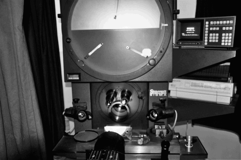
Microscopy
Samples with a surface width of 15 mm were used for microscopy in each of the test conditions. The samples were mounted in the bakelite moulds and grinded using sand papers starting from 200 to 1200 mesh size and polished with alumina papers starting from 5 to 0.1 μm until a lustrous smooth surface was obtained. The samples were then etched using Keller's reagent to reveal the grain structure. The optical microscopy was performed at OPTIKA B-600 MET equipment with magnifications of 200×, 500× and 1000× while the electron microscopy was performed at TESCAN Mira3 equipment with higher magnifications of 5000×, 10 000×, 25 000× and 50 000×.
Results and discussion
Mechanical testing
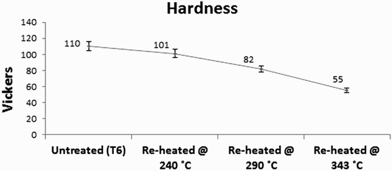
The material strength was found to decrease with increasing re-heating temperature, as shown in Fig. 6. Compared to the native T6 state, the yield and ultimate tensile strength (UTS) dropped by approximately 62 and 45.8% respectively after re-heating at 343°C. This reflects on the effect of precipitate coarsening and dislocation redistribution explained earlier.
1
,
12
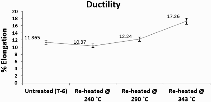
Re-heating at 240°C resulted in a mild drop of 1.8 and 5.6% in yield strength and UTS, respectively. This indicates small-scale structural changes at this temperature. A similar pattern was observed in the hardness tests with an approximate drop of 50% after re-heating at 343°C compared to the T6 state, as shown in Fig. 7. In contrast, the ductility was found to be mildly changed up till 290°C after which it shoots by up to 51.8% of the original T6 condition at the re-heating temperature of 343°C. Figure 8 shows the change of ductility with respect to the re-heating temperature.
Tensile test results for original T6 and re-heated conditions at different temperatures Hardness for original T6 and re-heated conditions at different temperatures %Elongation for original T6 and re-heated conditions at different temperatures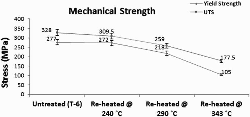
Machining test
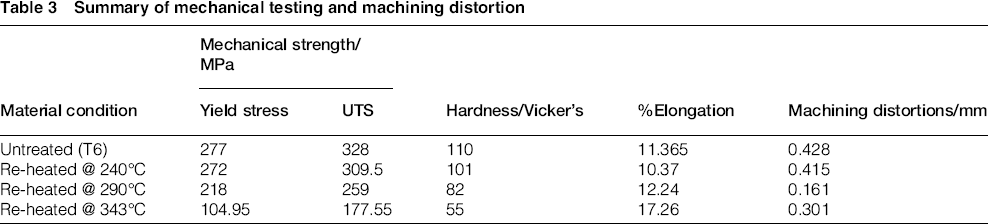
The results of the machining test together with the mechanical testing are summarised in Table 3. The table values are the average of two samples for each testing condition. The highest distortions were achieved at re-heating temperature of 240°C which is almost similar to the untreated condition. The samples treated at 290°C exhibited the lowest distortion while re-heating at 343°C yielded intermediate results. Figure 9 shows after machining distortions for each of the three re-heating conditions and the original T6 state.
After machining distortions for original T6 and re-heated conditions at different temperatures Summary of mechanical testing and machining distortion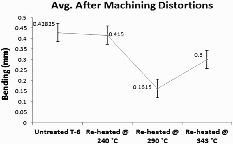
The results indicate that while higher temperature caused greater material softening, it was not equally effective in preventing the machining distortion. As mentioned earlier, the distortions are a combined effect of residual stresses both from the previous processing and the machining itself. Lower part thickness (below 2 mm) is particularly prone to distortion due to decreased material resistance. 16 , 17 Although re-heating at 343°C relaxed the thermally induced stresses, the accompanied material softening favoured the machining stresses due to which better results could not be achieved. It is observed that re-heating at 290°C balanced the two stresses well thereby improving the machining distortions. The distortions were reduced by up to 60% at 290°C with a corresponding decrease of 21% in strength. This is a workable solution for machining applications where slight loss of strength is tolerable. Re-heating at 240°C was found to bring insignificant structural changes for considerable improvement in distortion.
Microscopy
The results of both optical and electron microscopy show the sensitivity of secondary precipitates with respect to the re-heating temperature. The main factors which influence re-heating are coarsening of strengthening precipitates due to increased atomic diffusion, annihilation and redistribution of the dislocation cells, and the dissolution of existing precipitates at higher temperature. 1 , 10 , 12
Figure 10 shows the optical micrographs at 1000× magnification for samples in original T6 and re-heated condition at the three selected soaking temperatures. The arrows in Fig. 10 point towards over-aging in the form of increased black phase density as the re-heating temperature is increased. This black colour is characteristic of Mg2Si precipitates which take part in strengthening.
14
,
22
a Original T6 state, b re-heated at 240°C, c re-heated at 290°C, d re-heated at 343°C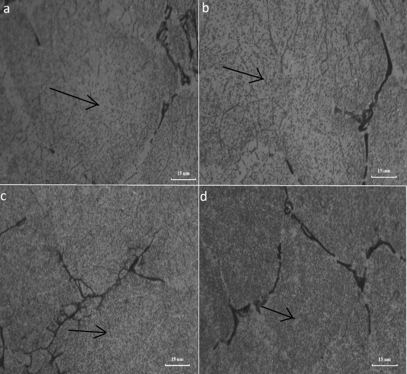
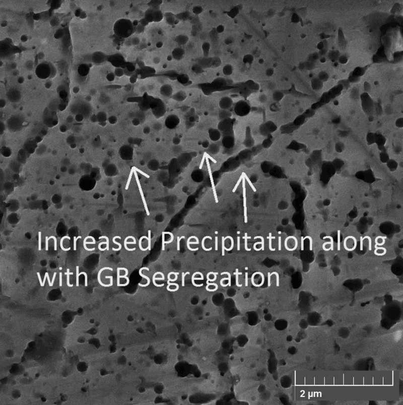
The micrographs also reveal the dissolution of precipitate clusters from the grain boundaries after re-heating at 343°C, as shown in Fig. 11. This effect is not visible at 240 and 290°C. These clusters are a major cause of inter-granular corrosion leading to stress corrosion cracking.
10
The presence of these clusters at grain boundaries however, provides added reinforcement and their dissolution further eases dislocation movement. This is one of the reasons for a 50% drop in material strength after re-heating at 343°C. Figure 11a shows the grain boundary precipitates in T6 condition while Fig. 11b shows their dissolution after re-heating at 343°C.
Depletion of grain boundary precipitates after re-heating above 300°C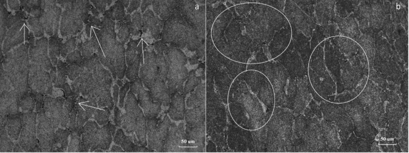
Figures 12
13
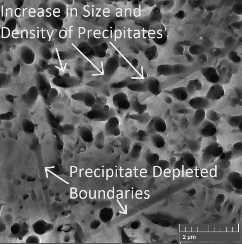
14
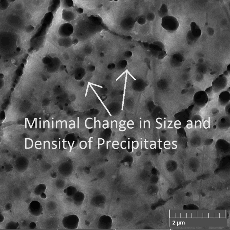
–15 show the electron micrographs at 25 000× magnification for samples in original T6 and re-heated conditions. The precipitates are now better resolved and an increase in their density and size can be seen with an increase in re-heating temperature. As the precipitates grow larger, their coherency with the base structure is lost resulting in a decrease in strength. The micrograph of re-heated condition at 343°C again shows precipitate depleted grain boundaries as seen in Fig. 15. The micrographs of original T6 and re-heated condition at 240°C have similar structural characteristics, as seen in Figs. 12 and 13, which explains the minimal difference of properties between the two conditions.
Original T6 state Re-heated at 240°C Re-heated at 290°C Re-heated at 343°C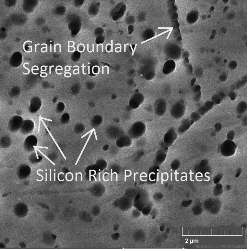
Conclusions
Re-heating reduces residual stresses for lesser distortions during the machining however it also lowers the material strength by directly affecting the secondary precipitates. This effect is proportional to the re-heating temperature hence lower temperatures are always preferable for re-heating.
Re-heating temperature above 300°C can reduce the strength of AA 6061 alloy by more than 50% with a simultaneous increase in ductility while re-heating below 240°C is found to be ineffective to induce sufficient structural changes for stress reduction. Re-heating temperature of 290°C was found to be the most effective in reducing machining distortions. The distortions were reduced up to more than 60% with a corresponding decrease in strength of 21%.
Both optical and electron micrographs reveal an increase in size and density of silicon rich strengthening precipitates with an increase in re-heating temperature. The difference in the mechanical properties and structural characteristics of original and re-heated condition at 240°C was found to be insignificant.
Footnotes
Acknowledgement
Financial support for this work by the National University of Sciences and Technology of Pakistan is gratefully acknowledged. The authors are utterly thankful to Mr. Naveed Hassan Siddiqui (Delft University of Technology, Delft, Netherlands) for his continual support and supervision throughout the course of study.