
Abstract
The article follows a resistance spot welding system, which integrates a six-axis industrial robot, power supply, pneumatic actuator, welder, cooler, trimmer, software control system, welding analyzer, force feedback sensor and welding fixture to realize monitoring of welding quality and real-time adjustment of welding parameters. Taking the resistance spot welding of 6 series aluminum alloy and DC06 galvanized steel as a study, four groups of electrode combinations, 16-6/16-6, 16-10/16-10, 16-7/16-10, and 16-5/16-16 (steel side/aluminum side), are selected for simulation and analysis, and the electrodes are optimized with the simulation results. By selecting the optimal electrode combination to carry out experiments and analyzing the influence of welding current and welding time on the joint performance, the average pulling shear force of the aluminum alloy steel resistance spot weld head is finally realized to exceed the average pulling shear force of the aluminum alloy aluminum resistance spot weld head, and the fracture is all started from the parent material of the alloy side to achieve the failure of the button, and ultimately a good welding effect is achieved.
Introduction
The introduction of welding automation equipment in environments with harsh working conditions and high risk factors has significantly reduced the number of production accidents and improved productivity and welding levels.1–3 Resistance spot welding, as the main connection method in body manufacturing, has the characteristics of low cost, high efficiency, high reliability and easy automation, which has great application potential as well as practical significance in realizing aluminum/steel connection.4,5 However, the metallurgical incompatibility between aluminum alloy steel and the huge difference in physical properties make the welding difficult, and not only that, the IMC layer (brittle intermetallic compound) generated at the aluminum/steel welding interface makes the mechanical properties of the joints deteriorate.6,7 Compared with the aluminum and steel bare plate welding, the presence of zinc layer not only greatly increases the welding current, but also causes the instability of the welding quality, which further reduces the mechanical properties of the joints, thus, the effective metallurgical connection of galvanized steel and aluminum alloy, as well as real-time control of the welding process and on-line adjustment has become a key and difficult problem in the field of welding automation.8,9 At present, the welding workstations applied on a large scale in factories rely on pre-programed programs to control industrial robots, welding power sources and workholding fixtures, which lack flexible adaptation to cope with different types of products, and likewise lack real-time adjustment of quality control and welding parameters during the welding process.10–13 In this paper, according to the welding mechanism of aluminum alloy galvanized steel resistance spot welding, the industrial robot system, welding power supply, pneumatic actuator, welding machine, cooler, trimmer, software control system and online welding monitoring sensor are integrated to design the intelligent welding system of aluminum/galvanized steel resistance spot welding, to improve the level of resistance spot welding intelligence, and combined with the simulation and SEM (Scanning Electron Microscope) analysis, to analyze the effect of the shape of the electrode cap on the welding performance of the joints, obtains the optimal welding process parameters, and then achieves good welding results.
Materials and welding stand
Material composition
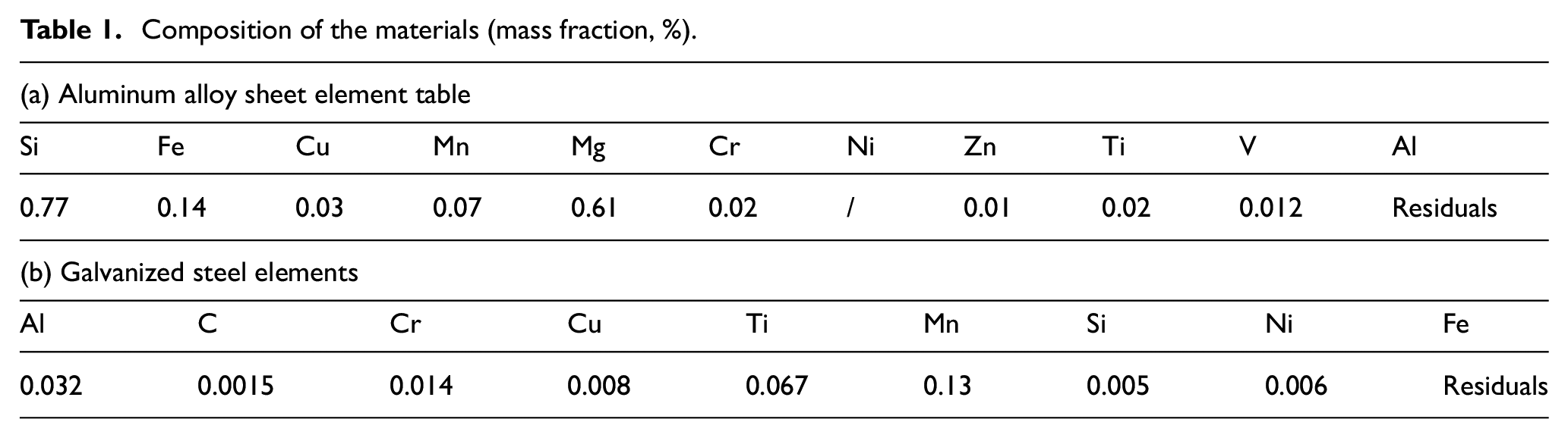
The materials used in the experiments were 1 mm thick 6016 aluminum alloy and 0.7 mm thick DC06 galvanized steel provided by Anshan Iron and Steel Group. These two materials are mainly used in automobile body welding, which is developed according to the demand of automobile lightweight. For automotive companies, the use of steel and aluminum alloy hybrid body structure, reasonable selection of materials, and the application of quantitative materials is one of the most effective means to ensure automotive safety, lightweight, low cost and other advantages. For the models of existing automobile brands, for example, the body of Audi A8 has changed from all-aluminum alloy to aluminum alloy and steel hybrid, and the body materials of Tesla Model 3 and Cadillac CT-6 have adopted aluminum-galvanized steel resistance spot welding process. The tensile strength of 6016 aluminum alloy is 222 MPa, the yield strength of 6016 aluminum alloy is 110 Mpa, and the galvanization was done by hot dip plating with a zinc layer thickness of 0.08 mm. The electrode material was Cr-Zr-Cu, see Table 1 below.
Composition of the materials (mass fraction, %).
Experimental platform
Welding system
The equipment used in this experiment for resistance spot welding and glue joint spot welding is a medium frequency DC (Direct Current) resistance spot welder. As shown in Figure 1, the entire welding system includes: a six-axis industrial robot, power supply, pneumatic actuator, welder, cooler, trimmer, software control system, welding analyzer, force feedback sensor and welding fixture. The experiment uses a six-axis highly automated medium frequency DC spot welding workstation with a simple software interface that matches the actual application environment, and is equipped with online welding monitoring sensors to monitor and adjust the changes of the welding process characteristics in a timely manner.

DC resistance spot welding system.
The main technical parameters are as follows, see Table 2.
Main technical parameters.

System composition
According to the operating process and system requirements, the system is controlled by a PLC (Programmable Logic Controller) as a general control, integrating various functional modules, and the system control diagram is shown in Figure 2.
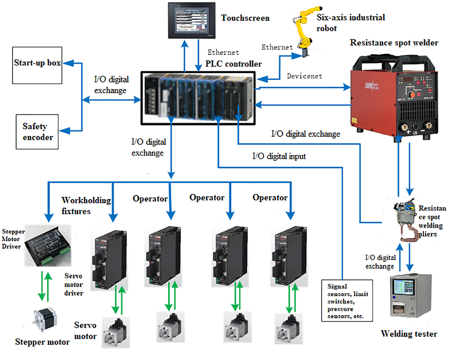
System control diagram.
Considering the technology, compared with many PLC brands, OMRON PLC’s programing method is more in line with the domestic programing habits, and it can save a lot of development time in the process of project realization. Therefore, OMRON PLC is selected.
Communication design
Resistance spot welder welding power supply and PLC communication mode
Resistance spot welder welding power supply can be extended PROFIBUS, DEVICENET, ETHERNET, REMOTE I/O and other interfaces, the four communication methods, OMRON PLC only supports DEVICENET and ETHERNET communication methods.
Depending on the requirements, both DEVICENET and ETHERNET communication methods can be used. Compared with ETHERNET communication, the fieldbus DEVICENET communication method adopts the master-slave polling access mode, which ensures the certainty and accuracy of information transmission, and in general the communication data volume is large using industrial ETHERNET, communication data volume is small using DEVICENET, welding power supply and PLC communication data volume is small, so the choice of DEVICENET communication mode.
Selection of communication between PLC, six-axis industrial robot and touch screen
There are two types of communication between CJ2M-CPU31, six-axis industrial robot and OMRON touch screen, namely, serial communication and industrial ETHERNET. In the current use of the project, the use of both can be, basically no difference. Considering the possible expansion of the system in the future, the amount of data exchanged may rise, and CJ2M-CPU31 built-in ETHERNET communication port, so the choice of industrial ETHERNET communication method.
Selection of communication method between startup box and PLC
Due to the startup box and PLC data exchange is very small, choose the most commonly used and the most reliable way, general-purpose hard wiring, go the way of aviation plug.
Servo drive and PLC communication mode selection
This system not only needs to four servo motors for positioning and speed control, but also need to linkage control. Therefore, the position control module is needed to control the servo drive, position control module and servo drive there are two ways of communication, respectively, industrial ETHERNET and hard-wired digital I/O mode. Both communication methods can meet our control requirements.
When using the hardwired digital I/O communication method, one position control module can only control a maximum of 2 or 4 servo drives. With the ETHERNET communication method, one position control module can connect up to 64 servo drives, but it is three times more expensive than the hardwired I/O position module. In this project, the PLC needs to control four servo drives, and the hard-wired I/O communication method is selected.
Stepping motor driver and PLC communication method selection
PLC control of stepper motor drives requires four signals: common, pulse signal input, direction signal input and offline signal input. Therefore, choose the most commonly used and most reliable hard-wired I/O communication method.
Welding tester and PLC communication method selection
Welding tester and PLC communication signals only start welding pressure control and close the welding pressure control signal, so choose the most commonly used and most reliable hard-wired I/O communication.
Specialized fixtures
In the experiment, when the pressure on the outer side of the electrode is insufficient, the extrusion on the periphery of the joint will cause the steel and aluminum plates to bulge, so the fixture is needed to apply extra pressure on the periphery of the joint to compress the workpiece, while suppressing spatter, increasing the aluminum-steel joint surface, and improving the joint strength. For the purpose of applying pressure to the periphery of the joint, suppressing buckling during welding of sample parts, reducing residual stress, and locking spatter, a universal resistance spot welding fixture was designed in conjunction with the weld clamp structure, including a housing, base plate, base, spring, and support block. The hole in the base plate is slightly larger than the diameter of the electrode rod, the housing is threaded for fastening, and two straight slots are reserved on the outside of the base plate. The base is mounted in the middle of the electrode and the electrode rod, with an insulating sleeve spacer left on the outside of the electrode, and the spring is pre-pressed in the device to fit the base plate and the base. The shell, base plate and pedestal are processed with high strength high temperature resistant insulating material, and the support block is made of insulating material. The normal work flow is: the electrode moves down, the shell first contacts with the weldment and pressurizes and gradually increases, the electrode moves down and extends from the shell reserved hole, contacts with the weldment and starts welding, the shell tab presses the weldment, the welding is completed, the electrode moves up, the shell continues to contact with the weldment and pressurizes and gradually decreases, until the spring returns to its original position and disengages from the weldment, the design diagram is shown in Figure 3.

Design diagram.
After delivering the design to the factory for production and processing, the fixture designed for resistance spot welding was used in experiments to squeeze the workpiece before, during and after welding, extend the squeezing time and extend the pressure application area to the periphery of the welded joints, which was used with good results and effectively suppressed the workpiece protrusion and spatter spray, and the photos of the experiments and installations are shown in Figure 4.

Comparison of the use effect and installation diagram: (a) without the use of tooling, some experimental parts bulge, (b) relatively flat after use, no bulging phenomenon, and (c) installation diagram.
Sample specifications
In order to ensure the accuracy of the experimental results, the samples were processed uniformly before the experiments. First, the original aluminum and steel sheets were cut by a shearing machine according to the specified dimensions, including 40 mm × 40 mm, 105 mm × 45 mm, and 150 mm × 50 mm. The edges of the cut specimens will have different degrees of burrs, which will form a path during the welding process and produce a shunt effect, resulting in a lower current at the weld joint than the actual input value, thus causing experimental fluctuations. Therefore, the burr is removed by grinding the edges of the test piece with a grinding wheel. In addition, in order to eliminate the influence of oil on the surface of the plate for the stability of welding, the polished test piece in batches into the ultrasonic cleaning machine degreasing 15 min, the cleaning agent selected Bransonic industrial ultrasonic cleaning agent, followed by a full wash with water and blow dry. It is worth noting that aluminum alloy and steel specimens need to be cleaned separately to avoid electrochemical corrosion during the cleaning process. The dimensional requirements of the experimental specimens are shown in Figure 5.

Sample part specifications.
Experimental procedure and analysis
Comparison of simulation of melting process
Electrode cap shape has a direct impact on current density, which in turn affects the heat output during welding, this article selected 16-6/16-6, 16-10/16-10, 16-7/16-10, 16-5/16-16 four groups of electrode cap combinations, the use of simulation methods to laterally compare the differences between different electrode cap shape nucleation process. The boundary conditions and assumptions used in the simulation process are as follows:
1) Aluminum and steel are isotropic materials, with the same thermophysical properties in all directions.
2) Neglecting the effect of convective heat transfer on the temperature field due to the flow of the melt after the material has melted.
3) The ambient temperature around the welded part is 20°C, the welding gun is a C-type gun, that is, the electrode moves up and down, without angular deflection.
The potential field distribution is modeled as shown in equation (1).

where
The transient heat transfer equation for the internal heat source is shown in equation (2).

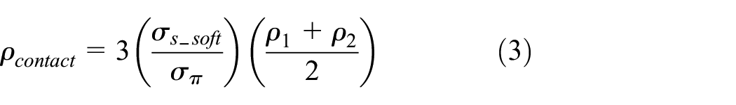
The contact resistance model is shown in equation (3).
The article uses Simufact Welding simulation software to simulate and compare the spatial and temporal evolution of the temperature field at the weld joint location under different electrode cap combinations. When the welding current is 13 kA, the simulation effect of the combination of four sets of electrode caps is shown in Figure 6.

Simulation effect at 13 kA: (a) 16-6/16-6 combination, (b) 16-10/16-10 combination, (c) 16-7/16-10 combination, and (d) 16-5/16-16 combination.
The 660°C temperature field ranges are shown in Figure 7.

660°C Temperature field at 13 kA: (a) 16-6/16-6 combination, (b) 16-10/16-10 combination, (c) 16-7/16-10 combination, and (d) 16-5/16-16 combination.
When the welding current is 15 kA, the simulation effect using a combination of four groups of electrode caps is shown in Figure 8.

Simulation effect at 15 kA: (a) 16-6/16-6 combination, (b) 16-10/16-10 combination, (c) 16-7/16-10 combination, and (d) 16-5/16-16 combination.
The 660°C temperature field ranges are shown in Figure 9.

660°C Temperature field at 15 kA: (a) 16-6/16-6 combination, (b) 16-10/16-10 combination, (c) 16-7/16-10 combination, and (d) 16-5/16-16 combination.
From the simulation results, it can be seen that the final temperature field distribution varies greatly with different electrode cap combinations, which explains the fact that under the 16-6/16-6 electrode combination, weld nuclei are most likely to form and are highly susceptible to spattering, along with larger surface indentations, while under the 16-10/16-10 electrode combination, the temperature field range in the weld joint area is the smallest and less likely to form aluminum nuclei.
The electrode combination pattern is drawn according to the simulation results, as shown in Figure 10.

Electrode combination law diagram.
As shown in Figure 10, the weld nucleus is the largest at both currents with the 16-6/16-6 electrode combination and the surface melting zone is the largest and most prone to adhesion, while the 16-5/16-16 combination ensures that the weld nucleus is large enough and the temperature field is concentrated in the center, reducing surface adhesion.
Effect of welding current on the surface, cross-section, tensile and shear properties of the joint
By combining the simulation results for the four sets of electrode cap combinations, it was found that the more severe the electrode surface attachment, the lower the electrode life. In order to improve the life of the electrode, considering the simulation results, the experiments were carried out using the symmetrical electrode combination of 16-5 on the steel side and 16-16 on the aluminum side. The steel side of the electrode cap for the 5 mm flat round electrode, aluminum side electrode cap for the 16 mm flat round electrode, electrode cap material for CrZrCu, the sample combination of 0.7 mm DC06 galvanized steel/1.0 mm 6016 aluminum alloy, welding monitor before welding to calibrate the welding current. During welding, the actual welding current measured by the welding monitor is recorded and the real-time data is transmitted to the main control system, which compares the real-time welding data with the set welding data and makes real-time adjustments to the welding parameters according to the comparison results to ensure that the actual welding parameters are consistent with the set welding parameters, and at the same time, the system automatically records the welding sequence and the parameters of the welding process. Under each welding parameter, two metallographic specimens, one peeling specimen, and three pulling shear specimens are welded.
After the results of trial welding, the experiment was selected to be carried out at a welding pressure of 3 kN, welding time of 300 and 400 ms, and the welding current was gradually increased from 15.5, 16, 16.5, 17 kA in four groups to analyze the effect of welding current on the surface, cross-section, tensile and shear properties, and the welding parameters are shown in the following Figure 11.

Welding process with variable welding current and variable welding time.
After cutting, grinding samples and light microscope measurement, taking photos and measuring data, using Origin to do line graphs, summarize the welding current and pulling shear force, welding current and weld core size change law is shown in Figure 12.

Relationship between welding current and tensile shear force, fusion nucleus size, aluminum side thickness.
Combined with the analysis of the experimental results, it can be seen that when the welding time is 300 ms, with the increase of welding current, the tensile shear force gradually increases, indicating that in the case of incomplete weld penetration and serious adhesion, increasing the welding current can effectively improve the tensile shear force. When the welding time is 400 ms, from the welding current of 16 kA, there is a large weld penetration, which leads to serious adhesion of the electrode on the aluminum side, and the pulling situation occurs during sampling, resulting in a decrease in the pulling shear force. At 17 kA, the electrode was replaced with a new one, the adhesion was reduced and the pulling shear force was slightly increased. When the welding time is 300 ms, the size of the weld core increases steadily with the increase of the current in the case of the sample piece not welded through, indicating that the increase of the welding current is favorable to the increase of the weld core, and when the weld core increases, the tensile shear force increases. When the welding current is 17 kA, the sample starts to weld through, and the size of the weld core decreases slightly, which indicates that the heat transfer to the aluminum alloy side is faster when the weld is through, and it is more directly to the aluminum alloy side and no longer grows directly to the core. When the welding time is 400ms, weld penetration occurs from a welding current of 16 kA, the size of the weld core appeared small fluctuations, no longer a significant increase in the size of the weld core. As the welding current increases, a slight thinning of the aluminum alloy plate occurs, and increasing the welding time causes greater thinning.
Effect of welding time on the surface, cross-section, tensile and shear properties of the joint
After trial welding, experiments in the welding pressure of 3 kN, welding current of 12 kA, welding time of 100, 200, 300, 400 ms in the case of four groups of welding, and then analyze the effect of welding time on the surface of the joint, cross-section, tensile and shear properties of the weld, welding parameters are shown in Figure 13 below.

Welding process with variation of welding time.
After cutting, grinding specimens and metallographic measurements, taking photos and measuring data, using Origin to do line graphs, summarize the welding time and tensile shear force, welding time and weld core size change law is shown in Figure 14.

Relationship between welding time and tensile shear force, fusion core size, and aluminum alloy side thickness.
From the metallographic measurements and tensile shear data, with the increase of welding time, the weld core gradually increases, and the tensile shear force increases with it, and it tends to stabilize from the welding time of 300ms, after which the size of the weld core increases slightly, and finally it stabilizes at about 5 mm. The thickness of the aluminum alloy side has a small decrease with the increase of welding time, the temperature field around the welded joint enters the equilibrium state, the strength of the heat-affected zone tends to stabilize, and the thinning process tends to stop.
SEM analysis of welded joints at optimum parameters
Through experimental analysis, it is found that the performance of welded joints is optimal when the welding pressure is 3 kN, the welding time is 300 ms, and the welding current is 16.5 kA. The article selects the optimal performance of the welded joint for SEM analysis, mainly analyzing the IMC layer trend and distribution pattern, zinc layer distribution area, the elements of the defects at the weld core when the button fails, and the location of the analysis is shown in Figure 15 below.

Shooting area map: (a) left edge, (b) weld core centre, (c) IMC layer, (d) right edge.
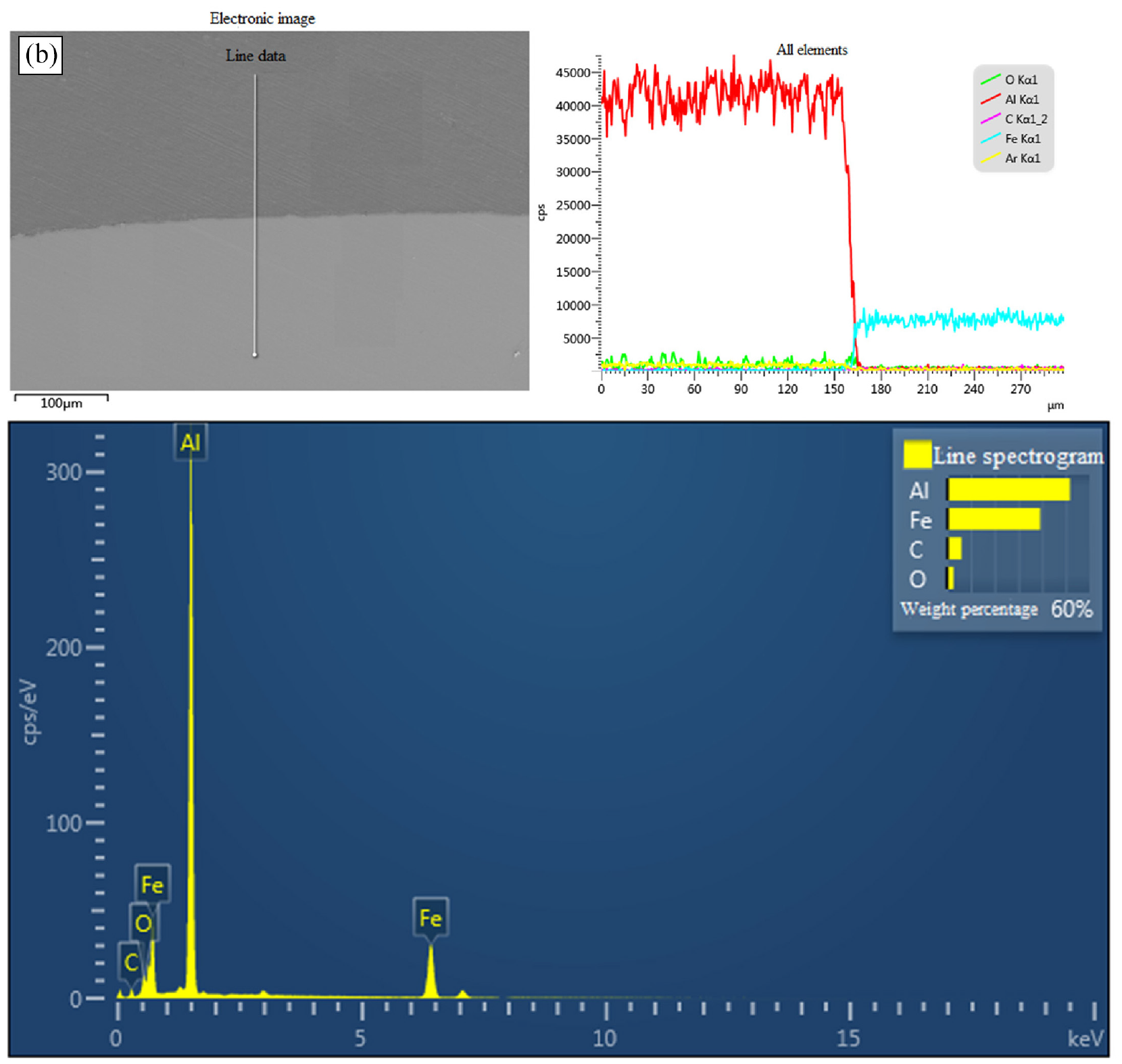
The article analyzes each shooting region shown in Figure 15, and the energy spectrum analysis report for region (a) is shown in Figure 16.

Energy spectrum analysis of photographed area (a).
The relevant energy spectrum analysis report for region (b) is shown in Figure 17.
Energy spectrum analysis of photographed area (b).
The relevant energy spectrum analysis report for region (c) is shown in Figure 18.

Energy spectrum analysis of photographed area (c).
The relevant energy spectrum analysis report for region (d) is shown in Figure 19.

Energy spectrum analysis of photographed area (d).
Button pulling and cutting sample weld core shooting position as follow Figure 20.

Metallographic sample of button welding core after pulling and shearing: (a) fracture (b) ligament fossa due to shear (c) ligament fossa due to positive stress.
Button failure specimen weld core defects are partially analyzed as shown in Figure 21.

Energy spectrum analysis diagram.
SEM analysis shows that the Zn element disappears in the center of the weld core and remains near the outer edges on both sides, indicating that the 16-5/16-16 electrode combination has an extrusion effect on the Zn element. There are cracks in the IMC layer, with an uneven distribution of thickness, and the elements are mainly Al and Fe, with the compounds FeAl3 and Fe2Al5,14–16 and trace Si, Mg, and Ag elements. Zn elements present at the outer edge of the weld core and the compounds produced by Al and Fe have lower metal bonding energy than FeAl3 and Fe2Al5,17–20 so the extrusion of Zn elements is conducive to improving the mechanical properties of welded joints.21–23 Porosity and inclusion defects were present at the weld core, and in situ observation experiments of the liquid aluminum/solid steel reaction revealed that the alumina film ruptured under thermal expansion, phase change expansion, and extrusion of the electrode, and liquid aluminum flowed through the alumina film cracks and contacted with the steel, and then interfacial reactions occurred, which moved the ruptured alumina film upward, an observation that explains the formation of inclusion defects. The welded joints have obvious slopes on the stripping side and large gaps at the interface, which shows that the slip fracture starts from the a side, the stress is concentrated to the c side, and when it reaches a certain threshold, it directly fractures from the c side, as shown in Figure 22, this result is consistent with the pattern of change in the tensile shear force-displacement curves of button shaped welded joints. The significant increase in tensile shear means that the welded joints obtained by the optimized welding process are stronger, resulting in better and more stable mechanical properties for the car body structure, which significantly improves the safety of the car.

Tensile shear force-displacement curves of welded joints with optimum welding parameters.
Through the analysis of the experimental results can be seen, in the case of unwelded and bonding is not serious, the increase in welding current and welding time is conducive to increasing the size of the weld core, which in turn enhances the tensile shear force of the joint, which is conducive to the generation of button failure weld core, and when the welded joint tensile shear specimens for the failure of the button weld core, the maximum tensile shear force. Soften the material around the welded joint is conducive to the generation of button failure nuclei, the thickness of the aluminum side will be thinned with the welding current and welding time, when the thermal equilibrium will be stabilized. The size of the nucleus will not increase or decrease further when the specimen is welded through. Excessive adhesion of the specimen to the electrode leads to a decrease or no increase in the tensile and shear forces, while weld penetration leads to a bulging of the weld core on the aluminum side. At the same time, the Zn element in the IMC layer of the weld core disappears from the center of the weld core and exists as a residue near the outer edge, indicating that the 16-5 on the steel side/16-16 on the aluminum side electrode combination has an extrusion effect on the Zn element, which is conducive to the enhancement of the mechanical properties of the welded joints.
Conclusion
Through the construction and implementation of the welding automation system, combined with experimental analysis, the following conclusions were drawn:
(1) The use of automated welding system realizes the process control and intelligent operation of resistance spot welding of aluminum-plated zinc steel, which is beneficial to realize the welding process monitoring and reduce the quality problems caused by welding parameter errors, and improve the quality of welded joints and welding efficiency.
(2) The auxiliary use of jigs and fixtures to squeeze the periphery of the joints before, during and after welding can effectively reduce the warping of the workpiece and the residual stress on the periphery of the joints after welding, which is conducive to the formation of the donut structure, locking the spatter at the outer edge of the joints, preventing spatter from flying out from the middle of the base materials, and improving the mechanical properties of the welded joints in terms of the mechanical structure.
(3) The optimization of electrodes is facilitated by simulation software, and the use of the steel-side 16-5/aluminum alloy-side 16-16 electrode combination shows that the small electrode on the steel side improves the current density on this side, and the large electrode on the aluminum alloy side improves the heat dissipation efficiency on its side. Heat conduction from the steel plate to the aluminum alloy plate during the welding process is conducive to avoiding weld-through and electrode sticking, while squeezing the zinc on the surface of the steel plate from the inside out is conducive to improving the performance of the welded joint.
(4) By analyzing the variation rules of welding current and welding time with respect to the size of weld core, tensile shear force and aluminum thickness, the optimal welding process parameters can be obtained, and the stable welding of resistance spot welding of aluminum galvanized steel can be realized.
Footnotes
Acknowledgements
The authors wish to thank for financial support.
Handling Editor: Chenhui Liang
Declaration of conflicting interests
The author(s) declared no potential conflicts of interest with respect to the research, authorship, and/or publication of this article.
Funding
The author(s) disclosed receipt of the following financial support for the research, authorship, and/or publication of this article: This work is supported by the National Natural Science Foundation of China under Grant 62163028, and is supported by the Key Research and Development Plan of Jiangxi Province under Grant 20202BBE53025 and Nanchang High Level Scientific and Technological Innovation Talents “Double Hundred Plan” under Grant 2020131.