
Abstract
Reconfigurable sheet metal fixtures are used to assemble sheet metal product families of similar locating layouts. These have to maintain locating and clamping layout fidelity for the entire range of a product family. Locating and clamping regions of a sheet metal part tend to dislocate and distort once subjected to nonequalized resistance spot welding guns. The resulted working regions are different in location and size from the original ones. In this article, Monte Carlo simulations are used by the authors to investigate the expected size and location of the working regions of parts in a sheet metal family subjected to random resistance spot welding forces. In the case study, proposed methodology is applied to an available automobile underbody floor panel family. Resulted working regions after the probabilistic deflection analysis are different from the initial ones both in size and location. The results show that by incorporating the random nonequalized clamping forces, the size of the working regions for fixturing elements is increased. Also, the possibility of designing a fixture that cannot assemble the full range of parts is reduced.
Keywords
Introduction
Contemporary product realization consists of two main ingredients. First, the product is designed based on the principles of “Design for Manufacture and Assembly.” Second, the individual components are manufactured using conventional and unconventional manufacturing processes that are then subsequently assembled. 1 Manufacturing companies of the recent era are facing volatile market conditions driven by rapid introduction of product variety and a continuously varying demand. Survival of the manufacturing companies depends upon their ability to develop products of high quality and low cost with the flexibility to give a prompt response to market changes. 2 Current manufacturing market scenario of short delivery time and volatile demand demands new manufacturing system attributes that can meet the requirements of high throughput and flexibility. 3 Transition from mass production to mass customization has resulted in a variety of manufacturing systems from dedicated manufacturing systems to flexible and reconfigurable manufacturing systems. Reconfigurable manufacturing systems can rapidly change their functionality and capacity to cope with diversifying variety and demand for a particular product family. Reconfigurable fixtures with the capability to locate and clamp all the members of a product family are the basic building blocks of reconfigurable assembly systems.
Mass production fixtures are dedicated fixtures with fixed locating and clamping elements. Reconfigurable fixtures were evolved in 1960s for machine tool industry. 4 These are made up of programmable fixturing elements. Design parameters’ evaluation in “sheet metal fixturing elements selection” is to synthesize the optimum working areas of individual robots. Working area synthesis of fixturing elements is a highly critical activity and failing to do so can cost potential capital loss. Sheet metal fixturing synthesis methodologies given by previous researchers are based on the assumption of ideal equalized welding guns. Welding guns used in sheet metal manufacturing are skewed and nonequilibrium in nature. Programmable sheet metal fixturing element synthesis conducted by previous researchers does not include nonequilibrium behavior of welding guns.
The work presented in this article is based on Monte Carlo simulations, and it evaluates the effect of random welding forces on the final optimum locating layout of the programmable fixturing elements for a reconfigurable sheet metal welding fixture. Monte Carlo simulations are performed for an automobile underbody floor panel family available in the literature to compute the actual working regions of individual fixturing robots. Monte Carlo simulations for sheet metal fixturing synthesis require the availability of statistical data of unequalized welding gun skewness.
Literature review
Recent past has witnessed an increase in customer need diversification that resulted in a new paradigm of mass customization, to manufacture customized products at near mass production efficiency and cost. Currently, sheet metal industry has to manufacture a variety of product families with available resources and with an ever-increasing stringent quality demands. Welding fixtures are the most important elements of compliant sheet metal assembly process being utilized in resistance spot welding assembly process.4–9 According to a study by Zhang et al., about 20% of the cost of sheet metal manufacturing and assembly system is consumed to develop fixtures, and furthermore, about 73% of sheet metal assembly variations are due to poorly designed fixtures. Mass customization emphasizes to develop robust reconfigurable fixtures to reduce lead times. 10 Huge amount of literature is available to synthesize dedicated fixturing workspace of both rigid and sheet metal assemblies. Literature available in the area of reconfigurable fixturing for compliant sheet metal parts is sparse as compared to rigid parts case.
Menassa and DeVries 11 used “3-2-1” rigid body locating scheme for compliant sheet metal case and devised an algorithm to compute the locating layout scheme to minimize deflection. Cai et al. 12 improved the previous work and replaced the classic “3-2-1” fixturing scheme with “N-2-1” fixturing scheme. Their work consisted of two steps: the first was to determine the optimum number of locators, “N,” and the second was to determine the optimum placement of the determined “N” locators. Camelio 13 proposed an algorithm to determine the optimum location of fixturing elements by attenuating part variation, tooling variation and spring back. Their optimization algorithm combined nonlinear programming methods and finite element methods (FEMs). Cai 14 utilized a robust design approach to find an optimum fixture locating layout scheme to minimize orientation and translational variations at predefined product characteristic points. Sheet metal variations are expressed as translational and orientational variations of the individual locating regions.
Previous research work on reconfigurable fixtures for compliant sheet metal fixtures is sparse as compared to the case of dedicated sheet metal fixtures. Lee et al. 15 produced the first ever published work for reconfigurable sheet metal fixturing synthesis. They utilized genetic algorithm to synthesize and optimize working envelopes of reconfigurable fixture elements by transforming the three-dimensional (3D) working envelopes into two-dimensional (2D) working envelopes. Kong and Ceglarek 16 build on the earlier work of Lee et al. 15 and utilized “Generalized Procrustes analysis” and pairwise optimization to synthesize and optimize working envelopes of reconfigurable fixturing elements. Their synthesis utilized industrial needs in the form of engineering requirement functions as cost functions in the overall optimization process. Li et al. 17 introduced a new flexible fixturing system. Parallel robots are used as reconfigurable modules in their work. Effect of six variations introduced in the overall resistance spot welding process chain is incorporated to make overall sheet metal fixturing robust and less sensitive. Baqai et al. 18 utilized algorithmic design approach for automated generation of architectural configurations. Walczyk and Munro 19 devised a new active bed of pin-based flexible fixturing device. The device suggested by Walczyk and Munro is used to locate and clamp sheet metal parts by utilizing the individual position of pins. Individual pin positions can be programmed and final position is controlled using electromechanical devices. Cai 20 optimized the compliant sheet metal fixture locating and clamping elements’ positions to minimize deflections by taking into account the real scenario of welding gun force variation. Cai utilized chi-square theorem to simplify and approximate the Monte Carlo simulation method. Cai transformed the Monte Carlo variation simulation into a deterministic model. Xing and Wang 21 developed a two-stage methodology to optimize sheet metal fixturing scheme. Response surface methodology and particle swarm optimization are used in their proposed scheme, which greatly reduces the number of finite element analysis (FEA). Fan and Senthil Kumar 22 combined Monte Carlo method and Taguchi method to evaluate a robust fixture locating layout.
Proposed methodology
Reconfigurable fixtures are the fundamental building blocks of the reconfigurable assembly systems. These are made up of programmable fixturing elements able to locate and clamp working regions of a particular family. Commercially available reconfigurable fixturing elements are either in the form of “Prismatic–Prismatic–Revolute (PPR) type robots” or “Stewart Platform–based robots.” PPR type robots have 3 degrees of freedom and generally known as Selective Compliance Arm for Robot Assembly (SCARA) robots. PPR robots are composed of two revolute joints and one prismatic joint. Stewart Platform–based robots possess 6 degrees of freedom. Dynamic response of Stewart Platform–based robots is fast as compared to PPR-based robots. Both of these are shown in Figure 1. Programming attributes of reconfigurable fixturing elements make reconfigurable fixtures different from dedicated fixtures, whose elements are fixed and rigidly positioned. 3D locating and clamping regions can be represented as filled cylinders. These filled cylinders, as shown in Figure 1, can be mapped either by 3 degrees of freedom PPR joint robots or 6 degrees of freedom Stewart Platform–based robots.
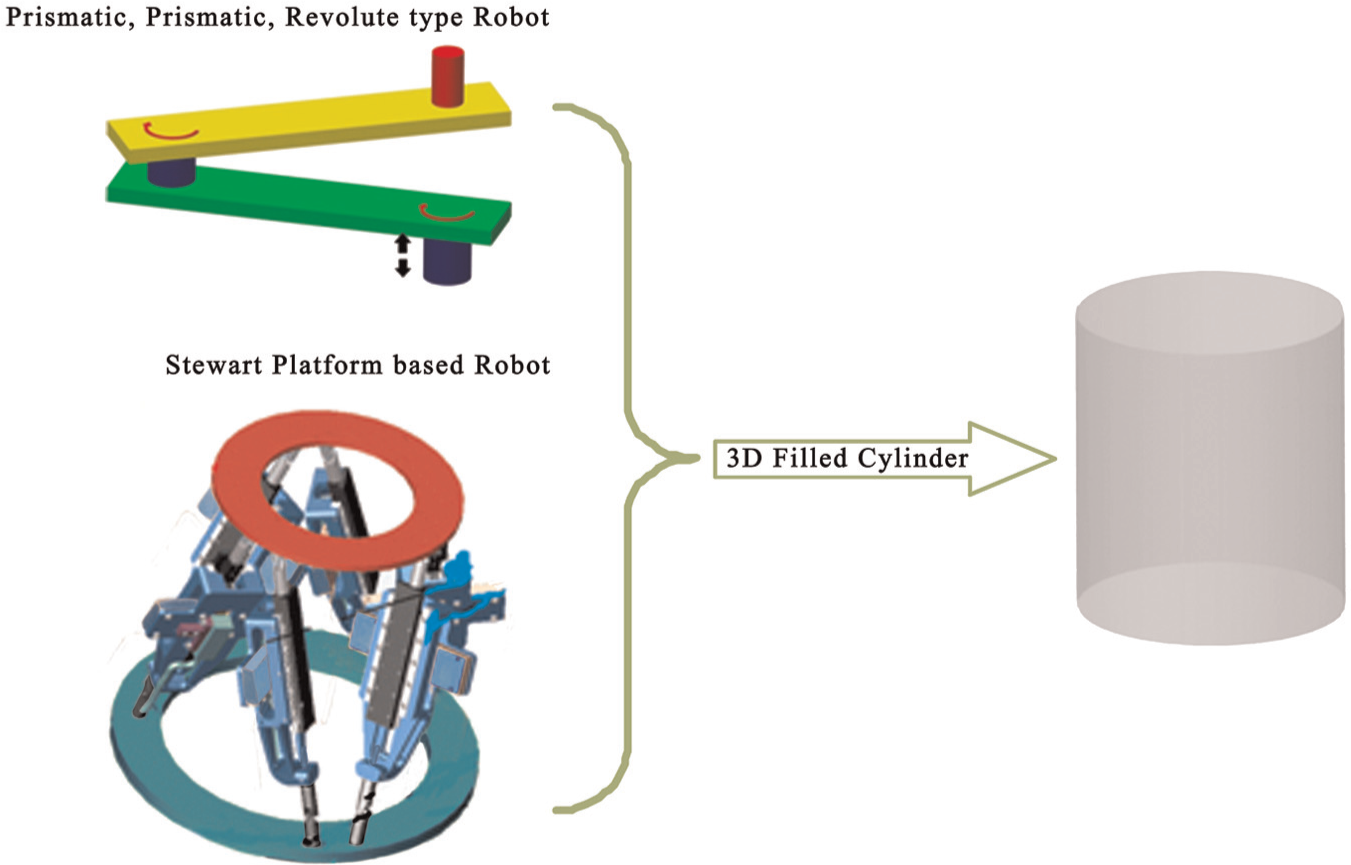
3D programmable fixture elements.
Regions of parts that come in contact with the programmable fixturing elements are called candidate working regions. Working scheme of reconfigurable fixtures is synthesized in such a way so as to accommodate all the candidate regions within the working areas of the corresponding individual programmable fixture robots.
The methodology presented in this article performs reconfigurable sheet metal fixture workspace synthesis by incorporating real-life actual phenomenon of nonequilibrium resistance spot welding forces. The work in this article expands on the earlier works conducted by Lee et al. 15 and Kong and Ceglarek. 16
Ideally, resistance spot welding gun pair exerts equal clamping forces on the compliant sheet metal assembly parts. Corresponding working regions remain well in their synthesized locations during welding. In real manufacturing environment, due to various unavoidable variations nonequilibrium forces are always present. These random nonequilibrium forces cause the synthesized working regions to deflect and distort to some random location and shape. Variation analysis is required to inculcate this phenomenon into the detailed synthesis. Individual plates and working regions remain the same during and after the welding process if the welding guns are equalized, but in actual welding scenario of nonequilibrium welding, working regions become distorted and cause the final synthesized reconfigurable working regions to be of a different size. Degree of distortion depends upon the skewness of the nonequilibrium welding guns of a manufacturing facility. Availability of statistical data of nonequilibrium welding guns of a manufacturing facility is of paramount importance in the selection of programmable fixturing robots.
Earlier works of Lee et al. 15 and Kong and Ceglarek 16 are extended by incorporating nonequilibrium welding gun–induced force–deflection variation analysis. Welding gun force imbalance is modeled as random force with standard normal distribution. Monte Carlo simulations are performed to evaluate the expected location of the working regions of individual sheet metal parts subjected to nonequilibrium resistance spot welding guns. Least square method is utilized at the end of the Monte Carlo simulation to minimize the Euclidean distance among every corresponding working region of all the sheet metal family members.
Synthesis scheme
Monte Carlo simulations are used to evaluate the expected working regions of individual sheet metal parts subjected to random, nonequilibrium resistance spot welding forces. Monte Carlo method for a single normal random welding force is explained for illustration. For a single normal random force, “

Expected value and variance of the sum of these trials are evaluated by expressions (2) and (3), respectively
The central limit theorem for any arbitrary interval (
By rearranging expression (4), a useful modified form is obtained to get the number of individual trials for a desired result to be within the specified probability limit
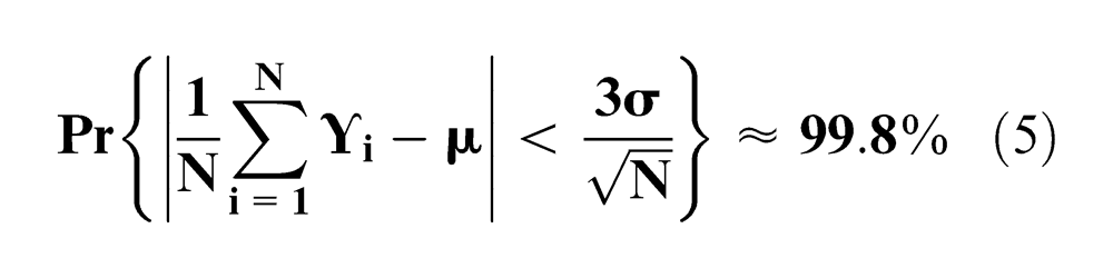
Expression (5) is an extremely important relation for calculating the error estimate and the number of iterations required for a simulation to be 99.8% confident about the results of the simulation.
Figure 2 depicts an example of a compliant sheet metal part family of two members. Both of these family members differ in size, shape and locating configuration within certain limits. These parts are located by seven locating regions for part 1 (
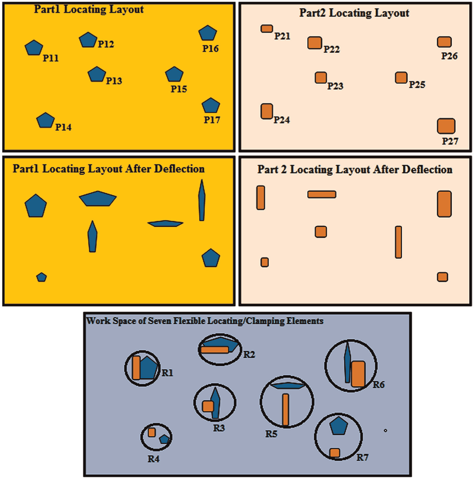
Reconfigurable fixture locating layout after deflection analysis.
Working regions of programmable fixturing elements are computed based on the expected distorted and deflected working regions of individual sheet metal parts. These working regions depicted in Figure 2 will be different from the ideal working regions synthesized without deflection analysis by Lee et al.
15
and Kong and Ceglarek.
16
A total of 7 regions (
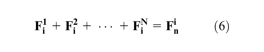
Constraint equation (6) introduces the fact that the sum of the force distributions among “
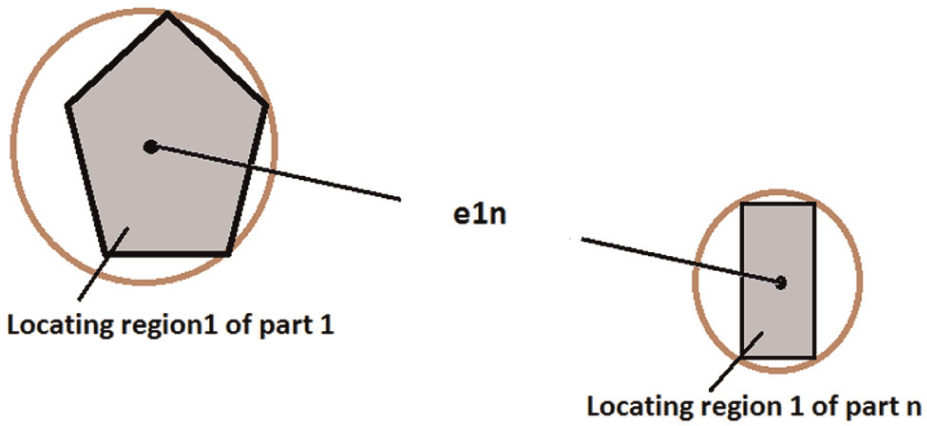
Euclidean distance between two respective locating regions.
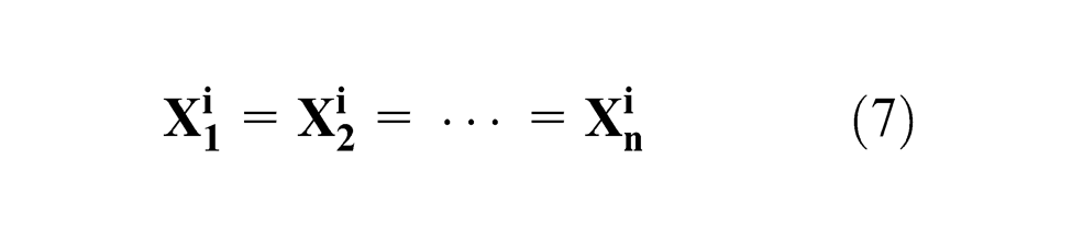
Therefore, the cost function to be minimized is the Euclidean distance among every respective locating region, “
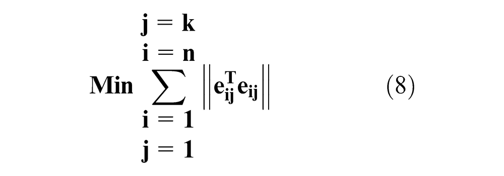
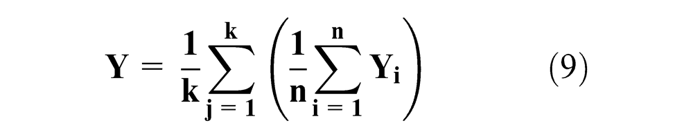
All the individual compliant sheet metal parts are translated such that the centroid of the polygon formed by joining the centers of the circumscribed circles of individual locating region polygons of an individual part coincides with the centroid of the fixture base plate. Fixture base plate centroid will be taken as the origin for further rotational motion to reduce the Euclidean distance among respective locating regions of individual parts. Centroid of the polygon formed by joining centers of the circumscribed circles of individual locating regions is computed conventionally as
Let “
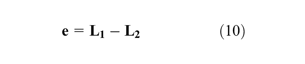
Coordinate difference, “
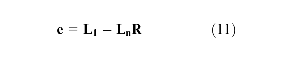
where “
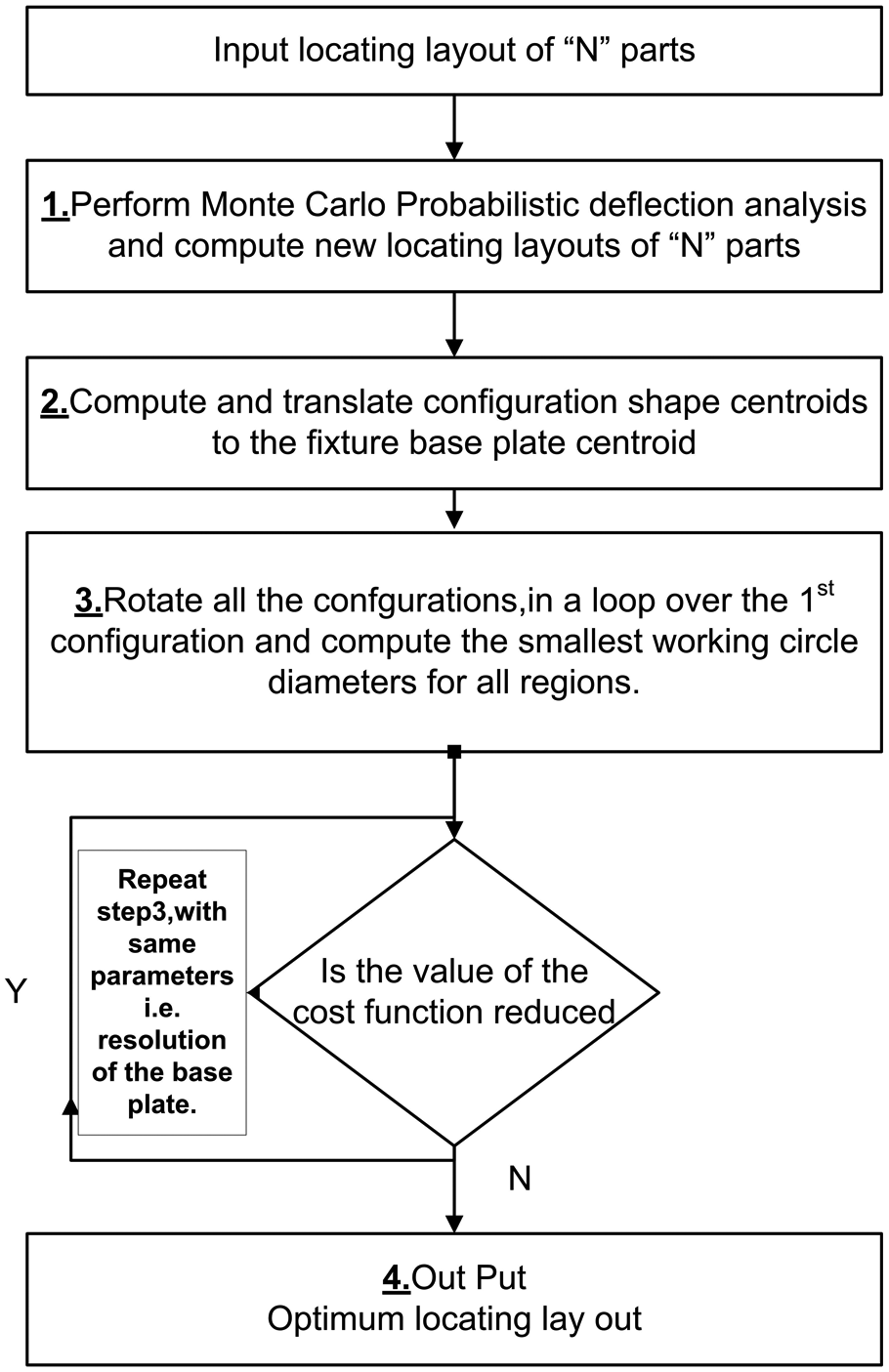
Block diagram of the proposed methodology.
Case study
Based on the proposed methodology, a case study is presented to demonstrate the effect of nonequilibrium welding forces on the selection of fixture elements. For this case study, exactly the same locating layout is used as was used by Kong and Ceglarek
16
for an automobile underbody floor panel family. Floor panel family is composed of a total of three members each having six working regions. Coordinate data of each individual working region after Monte Carlo deflection analysis are given in Appendix 1. Kong and Ceglarek
16
did not specify material properties of the sheet metal parts. Material properties selected for this work is of mild steel with Young’s modulus of elasticity “
Distortion due to welding heat is ignored similar to Cai et al. 12
Resistance spot welding of two-sheet thickness is considered only, that is any weld operation will be a process of joining two sheets together, instead of multisheets together, similar to Cai. 20
No weld sequence is considered; all the welding spots are assumed to be applied simultaneously, similar to Cai. 20
Figure 5 depicts the resistance spot welding process of part 1 for illustration.
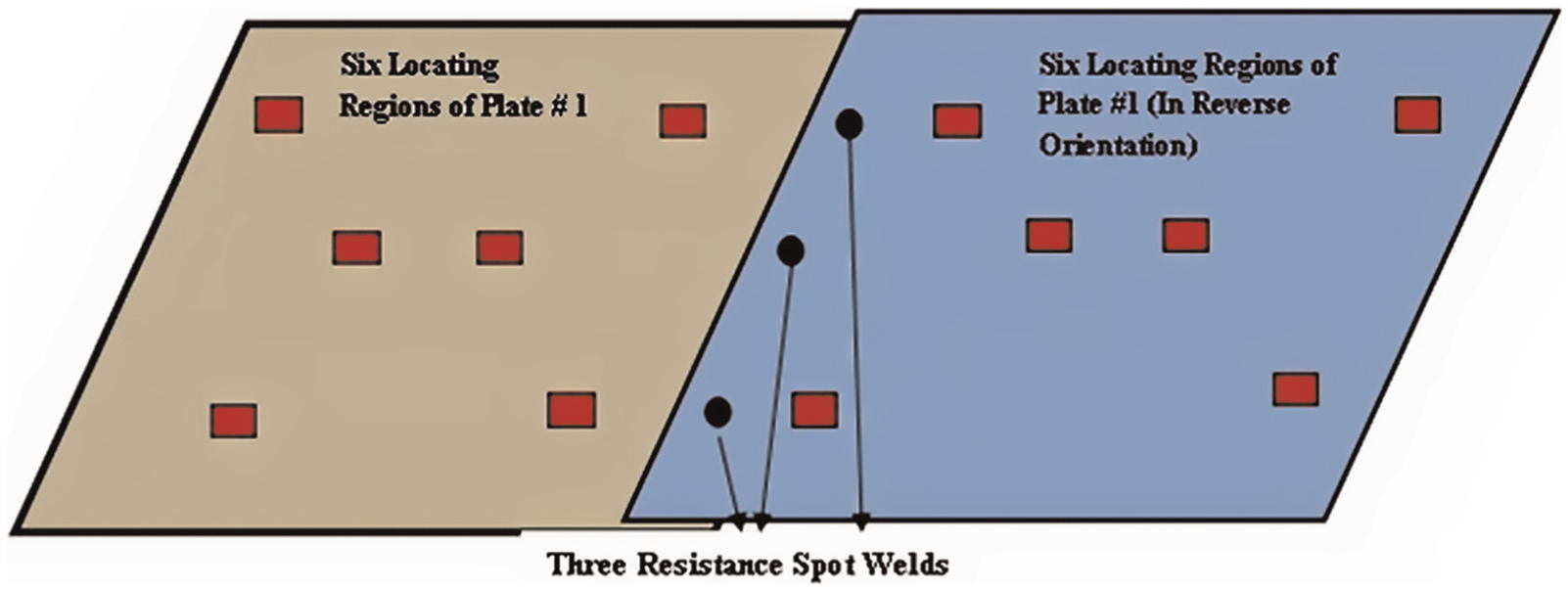
Resistance spot welding of plate 1.
Both the parts are resistance spot welded by three welding guns simultaneously and are equidistant from each other. Welding forces are random and are assumed to follow Gaussian distribution with zero mean and a SD of 10 N. All the forces are assumed to obey the same distribution. Fixture elements have to locate parts within the working region polygons. Deformed shape and deflected location of the working regions depend upon the exact location of the fixture elements within the working regions and the magnitude and location of the nonequilibrium welding force. Figure 6 presents one such instance during simulation for part 1 in which fixturing elements are located at the centroid of the working regions and three forces of magnitude 4, −3 and −7 N are applied at the plate end. Figure 6(a) shows positions of the FEA constraints and the three weld points. Figure 6(b) shows deformed shape of the assembly.
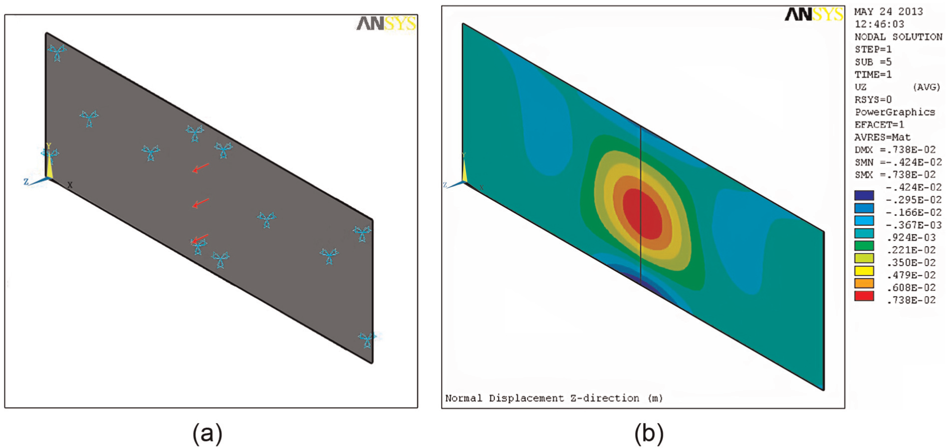
Part 1: (a) FEM constraints and (b) deformed shape of the assembly.
Expected deformed shape and location of the working region polygons depend on the random locations of the locating elements, nature of the applied random forces and the mechanical and geometrical properties of the sheet metal part. Monte Carlo simulation of the process was executed using ANSYS11 probabilistic design capabilities. Finite element of type “SOLID45” is used with dimensions, “47 × 47 × 2 mm.” Total number of elements for each individual plate was 5355. Simulation was run for a 200 number of trials for each part of the family. Location of the fixturing elements within working regions and the magnitude and direction of the welding gun forces for each simulation trial are randomly generated using Gaussian probability distribution. At the end of the simulation, deflection data recorded for all the 90 vertices of corresponding locating region polygons of the three parts are analyzed. Figures 7–9 depict the histograms of the frequency distribution of deflections at vertex 1 of locating region 1 of parts 1, 2 and 3.
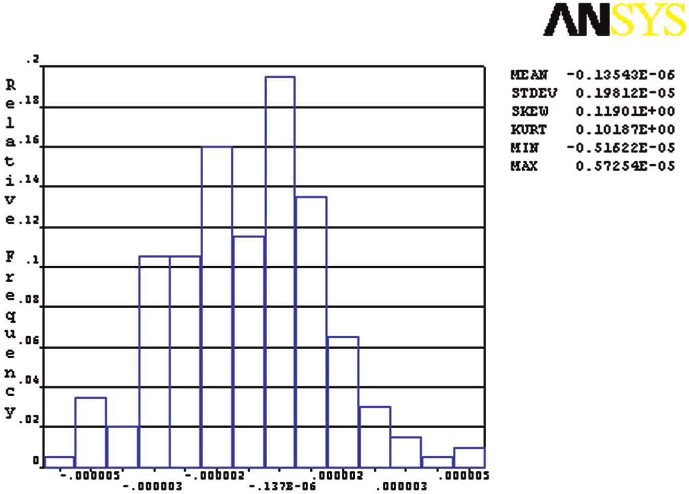
Frequency distribution of vertex 1 of locating region 1 of part 1.
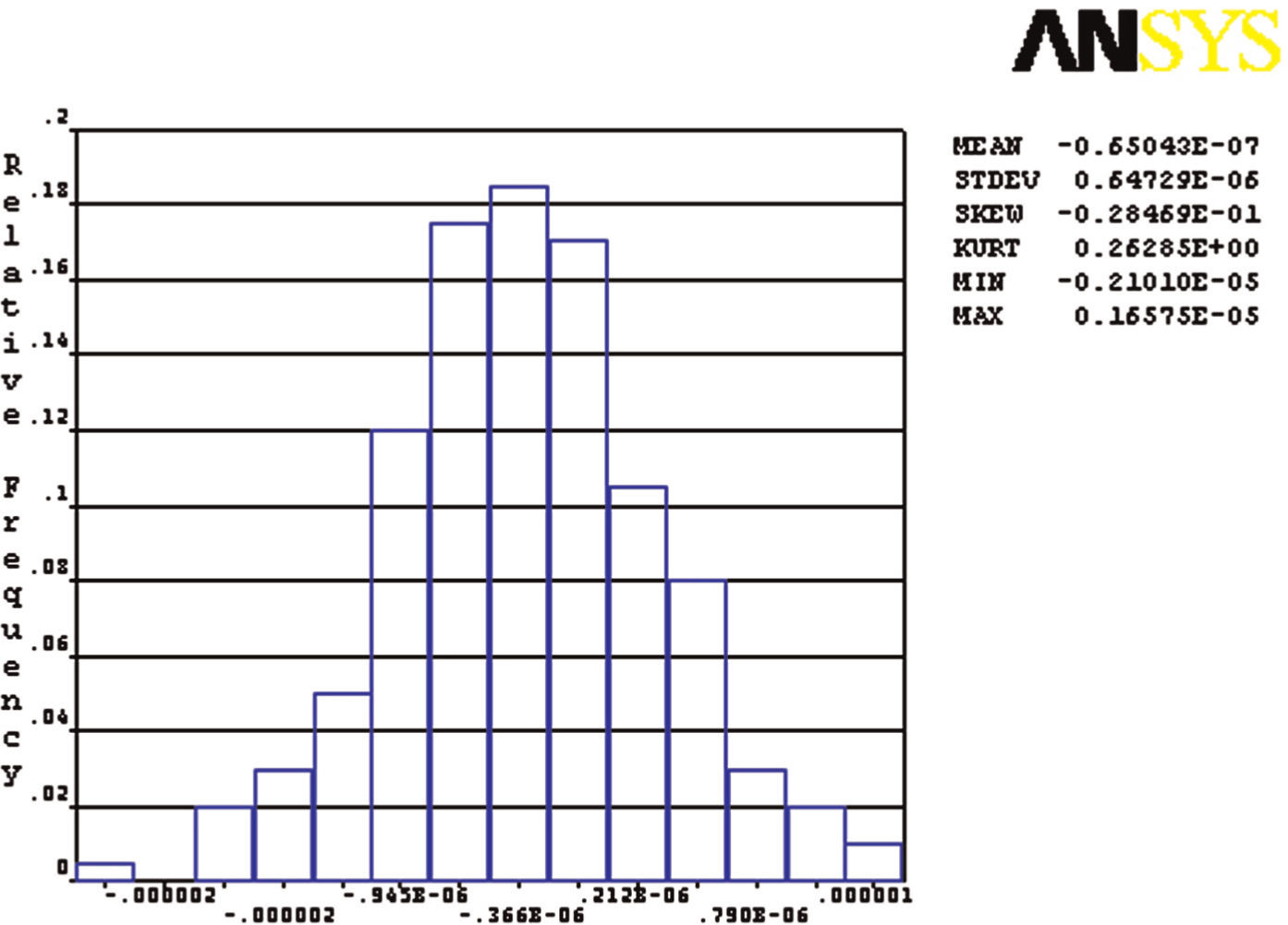
Frequency distribution of vertex 1 of locating region 1 of part 2.
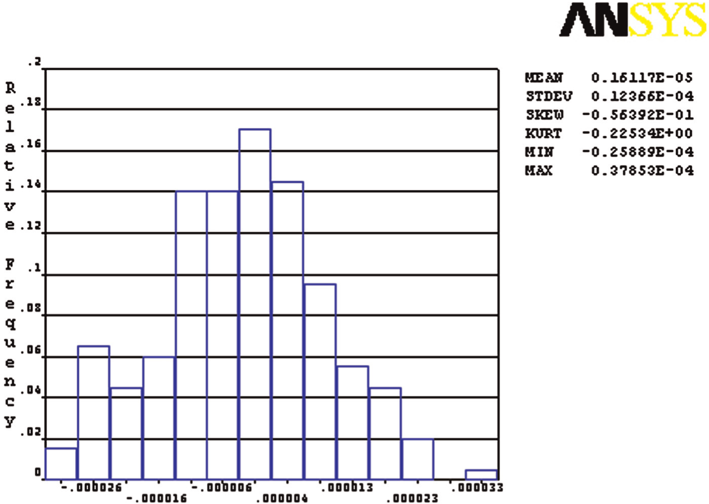
Frequency distribution of vertex 1 of locating region 1 of part 3.
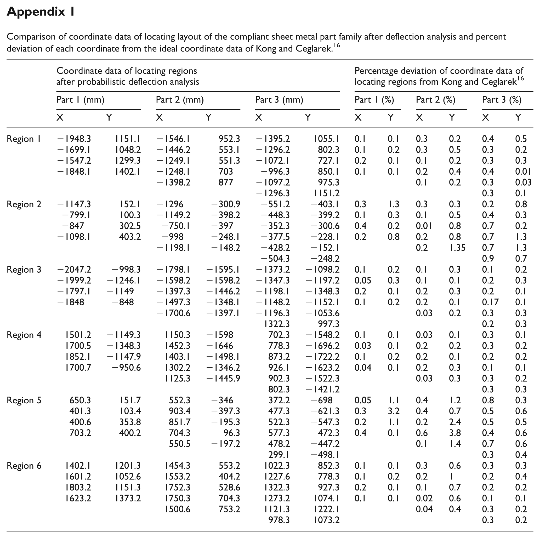
Expected value of deflection distribution at each vertex is computed and is used to compute the final position of vertices of the locating region polygons. These new locating regions’ polygon coordinates present the actual shape and size of the locating regions formed during real manufacturing scenario of nonequilibrium welding forces. Coordinate data of locating layout of the compliant sheet metal part family after deflection analysis are tabulated in Appendix 1. Percent deviation of each coordinate from the ideal coordinate data of Kong and Ceglarek 16 is also tabulated there for comparison.
Figure 10 depicts locating layout plan of the compliant sheet metal family after the deflection analysis. This layout plan is formed by translating all the parts polygon centroids to the base plate centroid and then subsequently reducing the Euclidean distance of the corresponding working regions. Working circle diameters presented in Figure 10 are different from the ideal data of Kong and Ceglarek. 16
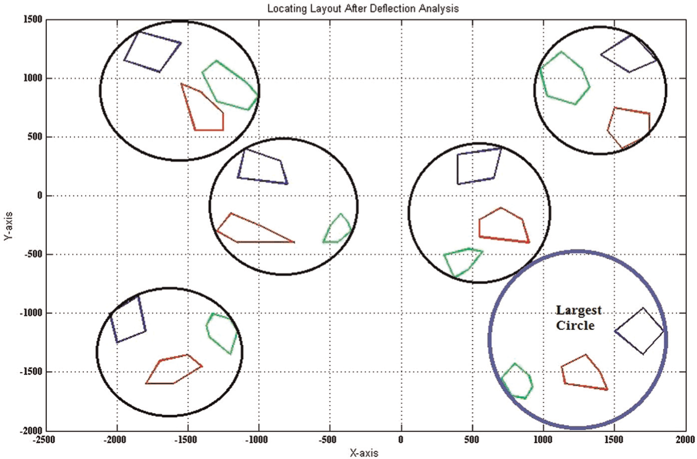
Reconfigurable fixture locating layout, after deflection analysis.
The difference between the ideal case and this work is due to the actual scenario of nonequilibrium welding clamping forces. After adjusting the coordinate data by the deflection analysis results, optimization algorithm is executed to reduce least square distance to minimize the working circle diameters simultaneously of all the tooling elements. Comparison of final total working circle diameters obtained for ideal equalized welding guns and practical nonequilibrium welding guns is tabulated in Table 1. Difference in results is due to the incorporation of real manufacturing scenario faced in practical manufacturing environment. It can be witnessed from the results that the incorporation of the actual nonequilibrium welding force scenario leads to a more practical selection of the programmable fixturing elements.
Comparison of total working circle diameters after optimization.
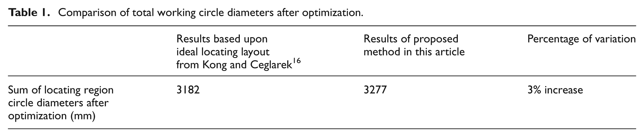
The results presented in this article are different and greater in magnitude from the optimum results of ideal equalized welding force case. The size of the reconfigurable fixturing elements is the main element that governs the cost of the reconfigurable fixtures. Optimum size of the fixturing elements is required to make it possible to accommodate all the compliant sheet metal parts of the family. Equalized welding gun analysis results in the selection of fixturing elements that will accommodate the compliant sheet metal parts only if all the welding guns are equalized. Nonequilibrium random welding forces used in this article will result in the selection of fixturing elements that will enable to accommodate all the compliant sheet metal parts subjected to the permissible random resistance spot clamping force of a manufacturing facility.
Conclusion
Reconfigurable sheet metal fixture layout synthesis is critical to calculate working regions of fixturing elements. In order to reduce the possibility of selecting fixturing elements that cannot accommodate the working regions of a part family, a two-stage method is proposed. Monte Carlo simulations are performed in the first stage to calculate the expected location and working areas of a part family subjected to nonequilibrium welding guns. Least square method is applied in the second stage to reduce the Euclidean distance among the corresponding working regions of the part family.
The following conclusions are drawn from the results.
Working regions of the parts deflect and distort from the initial position, and the difference is proportional to the nature of nonequilibrium welding guns’ clamping forces.
Working region computation based on the real-life manufacturing scenario of nonequilibrium welding guns results in different working areas as compared to ideal equalized welding gun scenario. Total working area computation in the case study resulted in 3% increase as compared to the ideal case of equalized welding guns.
Statistical data availability regarding the welding guns’ imbalance of a manufacturing facility is critical to produce reliable results of Monte Carlo simulations.
Footnotes
Appendix
Comparison of coordinate data of locating layout of the compliant sheet metal part family after deflection analysis and percent deviation of each coordinate from the ideal coordinate data of Kong and Ceglarek. 16
| Coordinate data of locating regions after probabilistic deflection analysis |
Percentage deviation of coordinate data of locating regions from Kong and Ceglarek
16
|
|||||||||||
|---|---|---|---|---|---|---|---|---|---|---|---|---|
| Part 1 (mm) |
Part 2 (mm) |
Part 3 (mm) |
Part 1 (%) |
Part 2 (%) |
Part 3 (%) |
|||||||
| X | Y | X | Y | X | Y | X | Y | X | Y | X | Y | |
| Region 1 | −1948.3 | 1151.1 | −1546.1 | 952.3 | −1395.2 | 1055.1 | 0.1 | 0.1 | 0.3 | 0.2 | 0.4 | 0.5 |
| −1699.1 | 1048.2 | −1446.2 | 553.1 | −1296.2 | 802.3 | 0.1 | 0.2 | 0.3 | 0.5 | 0.3 | 0.2 | |
| −1547.2 | 1299.3 | −1249.1 | 551.3 | −1072.1 | 727.1 | 0.2 | 0.1 | 0.1 | 0.2 | 0.3 | 0.3 | |
| −1848.1 | 1402.1 | −1248.1 | 703 | −996.3 | 850.1 | 0.1 | 0.1 | 0.2 | 0.4 | 0.4 | 0.01 | |
| −1398.2 | 877 | −1097.2 | 975.3 | 0.1 | 0.2 | 0.3 | 0.03 | |||||
| −1296.3 | 1151.2 | 0.3 | 0.1 | |||||||||
| Region 2 | −1147.3 | 152.1 | −1296 | −300.9 | −551.2 | −403.1 | 0.3 | 1.3 | 0.3 | 0.3 | 0.2 | 0.8 |
| −799.1 | 100.3 | −1149.2 | −398.2 | −448.3 | −399.2 | 0.1 | 0.3 | 0.1 | 0.5 | 0.4 | 0.3 | |
| −847 | 302.5 | −750.1 | −397 | −352.3 | −300.6 | 0.4 | 0.2 | 0.01 | 0.8 | 0.7 | 0.2 | |
| −1098.1 | 403.2 | −998 | −248.1 | −377.5 | −228.1 | 0.2 | 0.8 | 0.2 | 0.8 | 0.7 | 1.3 | |
| −1198.1 | −148.2 | −428.2 | −152.1 | 0.2 | 1.35 | 0.7 | 1.3 | |||||
| −504.3 | −248.2 | 0.9 | 0.7 | |||||||||
| Region 3 | −2047.2 | −998.3 | −1798.1 | −1595.1 | −1373.2 | −1098.2 | 0.1 | 0.2 | 0.1 | 0.3 | 0.1 | 0.2 |
| −1999.2 | −1246.1 | −1598.2 | −1598.2 | −1347.3 | −1197.2 | 0.05 | 0.3 | 0.1 | 0.1 | 0.2 | 0.3 | |
| −1797.1 | −1149 | −1397.3 | −1446.2 | −1198.1 | −1348.3 | 0.2 | 0.1 | 0.2 | 0.3 | 0.2 | 0.1 | |
| −1848 | −848 | −1497.3 | −1348.1 | −1148.2 | −1152.1 | 0.1 | 0.2 | 0.2 | 0.1 | 0.17 | 0.1 | |
| −1700.6 | −1397.1 | −1196.3 | −1053.6 | 0.03 | 0.2 | 0.3 | 0.3 | |||||
| −1322.3 | −997.3 | 0.2 | 0.3 | |||||||||
| Region 4 | 1501.2 | −1149.3 | 1150.3 | −1598 | 702.3 | −1548.2 | 0.1 | 0.1 | 0.03 | 0.1 | 0.3 | 0.1 |
| 1700.5 | −1348.3 | 1452.3 | −1646 | 778.3 | −1696.2 | 0.03 | 0.1 | 0.2 | 0.2 | 0.3 | 0.2 | |
| 1852.1 | −1147.9 | 1403.1 | −1498.1 | 873.2 | −1722.2 | 0.1 | 0.2 | 0.2 | 0.1 | 0.2 | 0.2 | |
| 1700.7 | −950.6 | 1302.2 | −1346.2 | 926.1 | −1623.2 | 0.04 | 0.1 | 0.2 | 0.3 | 0.1 | 0.1 | |
| 1125.3 | −1445.9 | 902.3 | −1522.3 | 0.03 | 0.3 | 0.3 | 0.2 | |||||
| 802.3 | −1421.2 | 0.3 | 0.3 | |||||||||
| Region 5 | 650.3 | 151.7 | 552.3 | −346 | 372.2 | −698 | 0.05 | 1.1 | 0.4 | 1.2 | 0.8 | 0.3 |
| 401.3 | 103.4 | 903.4 | −397.3 | 477.3 | −621.3 | 0.3 | 3.2 | 0.4 | 0.7 | 0.5 | 0.6 | |
| 400.6 | 353.8 | 851.7 | −195.3 | 522.3 | −547.3 | 0.2 | 1.1 | 0.2 | 2.4 | 0.5 | 0.5 | |
| 703.2 | 400.2 | 704.3 | −96.3 | 577.3 | −472.3 | 0.4 | 0.1 | 0.6 | 3.8 | 0.4 | 0.6 | |
| 550.5 | −197.2 | 478.2 | −447.2 | 0.1 | 1.4 | 0.7 | 0.6 | |||||
| 299.1 | −498.1 | 0.3 | 0.4 | |||||||||
| Region 6 | 1402.1 | 1201.3 | 1454.3 | 553.2 | 1022.3 | 852.3 | 0.1 | 0.1 | 0.3 | 0.6 | 0.3 | 0.3 |
| 1601.2 | 1052.6 | 1553.2 | 404.2 | 1227.6 | 778.3 | 0.1 | 0.2 | 0.2 | 1 | 0.2 | 0.4 | |
| 1803.2 | 1151.3 | 1752.3 | 528.6 | 1322.3 | 927.3 | 0.2 | 0.1 | 0.1 | 0.7 | 0.2 | 0.2 | |
| 1623.2 | 1373.2 | 1750.3 | 704.3 | 1273.2 | 1074.1 | 0.1 | 0.1 | 0.02 | 0.6 | 0.1 | 0.1 | |
| 1500.6 | 753.2 | 1121.3 | 1222.1 | 0.04 | 0.4 | 0.3 | 0.2 | |||||
| 978.3 | 1073.2 | 0.3 | 0.2 | |||||||||
Declaration of conflicting interests
The authors declare that there is no conflict of interest.
Funding
This research received no specific grant from any funding agency in the public, commercial or not-for-profit sectors.