
Abstract
This paper presents the design of a symmetric variable stiffness joint that employs worm gear and sliding helical transmissions to adjust the effective length of the leaf springs. Firstly, the design concept and working principle of the variable stiffness joint are presented, along with two different assembly methods. Secondly, the stiffness equations and characteristics of the variable stiffness joint are then derived and analyzed. Next, the dynamics of the variable stiffness joint are modeled and simulated visually using Simulink. Finally, a prototype of the variable stiffness joint is constructed and its stiffness characteristics are experimentally verified. The experimental results demonstrate that both assembly methods are capable of adjusting the stiffness and position of the joint within a certain range. This study contributes to the understanding and development of symmetric variable stiffness joints by presenting a comprehensive design, analysis, simulation, and experimental evaluation. The proposed joint has potential applications in various fields that require adaptability, adjustability, and safety.
Keywords
Introduction
Robots are automated devices that can perceive the environment, perform tasks and interact, playing important roles in various fields such as industry, military, medicine, service, etc. Traditional robots are composed of rigid components, requiring more precise sensors and controllers to give them the advantages of high accuracy and high load, but they also have some disadvantages, such as being stiff, heavy, easily disturbed, and difficult to adapt to complex environments. More seriously, traditional rigid robots lack safety and need to strictly control their motion trajectories and torques to prevent them from harming people or the environment during work.1–3 In recent years, the utilization of robots has significantly expanded across various industries, particularly in non-industrial domains such as public services, medical rehabilitation, and military security. This widespread deployment necessitates enhanced standards for robot safety, given the escalating frequency of human-robot interactions. Ensuring the well-being of humans and promoting environmental protection have emerged as paramount concerns in these contexts. 4
To address these demands, researchers have proposed the development of soft robots, which are composed of flexible joints. These joints incorporate novel elastic components or mechanisms that enable variable stiffness, allowing the robots to adapt to different conditions and interactions. Researchers have also improved the actuation mechanisms of these robots to enhance their flexibility and adaptability. 5 Further, researchers have radically improved the flexibility and adaptability of robots by improving their drive joints. One early solution for flexible joints was the Series Elastic Actuators (SEA), 6 which introduced non-adjustable nonlinear elastic elements between the drive unit and the controlled object. This way, the drive unit could reduce collision impact and absorb energy from impacts with the help of the elastic elements. However, the non-adjustable stiffness of SEA limited its practical applications and posed challenges in widespread adoption. Subsequently, researchers developed a Variable Stiffness Joint (VSJ) that can change the stiffness of the output link regardless of position. 7 The most important difference between VSJ and SEA is that VSJ can change the stiffness of the output link, regardless of the position. This structure is usually driven by a joint motor to move the load, and by a stiffness motor to adjust the joint stiffness. Therefore, researchers have been more interested in studying variable stiffness joint (VSJ) in recent years.8,9
Wolf and Hirzinger 10 from the German Aerospace Center (DLR) designed a variable stiffness structure (VS-Joint) based on coil springs, which is based on the principle of incorporating a spring element between the drive motor and the output linkage, with the stiffness motor controlling the variable stiffness. Subsequently, Wolf et al. 11 optimized the spring structure so that the variable stiffness mechanism was connected in parallel with the output shaft, which resulted in a more compact structure. Zhu and Thomas 12 designed an innovative variable stiffness mechanism by using the principle of variable pivot point of cams and levers, which can be optimized by optimizing the shape of the cams to improve the stiffness performance. The VSJ using leaf springs was proposed by Yang et al. The effective length of the spring can be changed by a crank-slider mechanism to achieve a wide range of stiffness variatio. 13 Wu et al. 14 combined cams and leaf springs to realize a VSJ that can be combined with one or more leaf springs, and the stiffness range of the joint is determined by the number of springs used.
Awad et al. 15 proposed a combination of torsion spring and lever principle to vary the stiffness of the joint by changing the load position of the joint, the advantage is that it allows the joint to be adjusted in the range of zero and maximum stiffness. Jafari et al. 16 used a rolling screw to move the spring to change the effective arm of the lever, but due to the large design of the joint dimensions it is only suitable for exoskeleton joints. Zhang et al. 17 designed a novel variable stiffness joint using a permanent magnet mechanism instead of a linear spring, but the joint size is large and two motors are needed to control the gap of the permanent magnet mechanism to change the joint stiffness. Junho Choi et al. proposed a variable stiffness joint based on permanent magnets. The structure consists of two concentric rings with different radii, and each ring consists of four curved magnets and four curved spacers, which is more novel, has a smaller size and can reach almost zero stiffness. 18
The flexible variable stiffness joint studied in this paper is an important category of flexible joints, which has mechanically adjustable stiffness characteristics. This kind of mechanical VSJ has been gradually applied to the robot joints for human-robot interaction because of its smaller structure size and larger adjustable stiffness range. Robots with this kind of joint have higher safety and environmental adaptability, enabling them to interact with people or objects in complex environments, such as polishing, assembling, human-robot collaboration, etc. Flexible joint robots can also use joint flexibility to compensate for torque and reduce impact, improving the position control accuracy and force control performance of the robotic arm.
Mechanical design and theoretical analysis of VSJ
In this paper, we present the design of a VSJ that achieves stiffness variation by utilizing a turbine-worm drive to adjust the joint position and a sliding helical drive to modify the effective length of the leaf springs. This innovative mechanism enables us to control the stiffness of the joint flexibly. The VSJ features a symmetrical structure, allowing for two different assembly schemes that offer distinct stiffness ranges. To achieve this, the joint is equipped with two motors, namely a joint motor and a stiffness motor. These motors work in tandem to enable the joint to adapt its stiffness based on the requirements of the human-computer interaction scenario.
To illustrate the working principle of the VSJ system, we provide a detailed schematic diagram in Figure 1. This diagram visually demonstrates how the joint adjusts its position and modifies the effective length of the leaf springs, ultimately resulting in variable stiffness. By presenting this design, our paper contributes to the advancement of VSJ and their applications in human-robot interaction scenarios. The proposed joint provides a flexible and adaptive solution for achieving optimal stiffness control and enhancing safety in various domains.

Schematic diagram of variable stiffness joint.
Mechanical design
As depicted in Figure 2, the mechanical structure of the VSJ utilizes a worm gear transmission to adjust the joint position, with the turbine worm serving as a deceleration mechanism. The joint motor directly rotates the worm gear, which subsequently drives the turbine. The worm gear is fixed within the housing through bearings at both ends, while the stiffness motor is installed inside the turbine. One end of the screw is connected to the stiffness motor, and the other end is secured within the turbine using bearings. Inside the two inner housings, two guide rails are mounted along the symmetry center of the turbine. Additionally, two leaf springs are positioned inside the inner housings along the same symmetry center. Figure 3 provides a visual representation of this arrangement.

Structural model of VSJ.
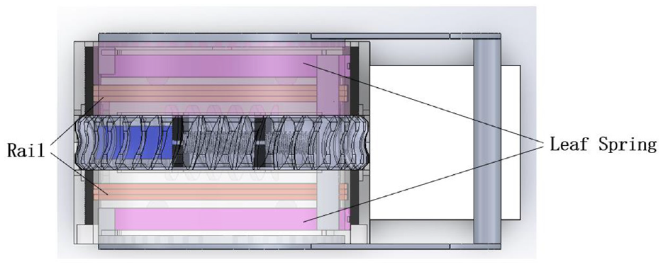
Top view of a VSJ.
By controlling the rotational angle of the screw, the stiffness motor adjusts the position of the nut along the guide rails, thereby modifying the effective length of the leaf springs continuously.
The overall joint configuration employs a symmetrical structure. The output rod, connected to the inner shell through bearings, features limiting blocks at each end. These limiting blocks pass through the corresponding limiting holes in the two inner shells, securing the movable ends of the leaf springs. This design enables the joint to achieve continuous stiffness variation. The use of symmetrical construction ensures that the joint remains balanced when exposed to external moments. Moreover, the added limit holes in the inner shell prevent plastic deformation caused by excessive strain on the leaf springs.
The joint mechanism designed in this paper is a symmetric structure, so there are two possible assembly schemes, which have the same design principle and meet the design requirements, as shown in Figure 4. In scheme I, the fixed ends of the two leaf springs are located on the side away from the stiffness motor, and the free ends are on the same side as the stiffness motor. Therefore, the larger the output angle of the stiffness motor, the longer the effective length of the leaf springs. This scheme allows a lower stiffness range. In scheme II, the fixed ends of the two leaf springs are on the same side as the stiffness motor, and the free ends are on the side away from the stiffness motor. Therefore, the larger the output angle of the stiffness motor, the shorter the effective length of the leaf springs. This scheme can achieve a higher stiffness range. The joint parameters are shown in Table 1.
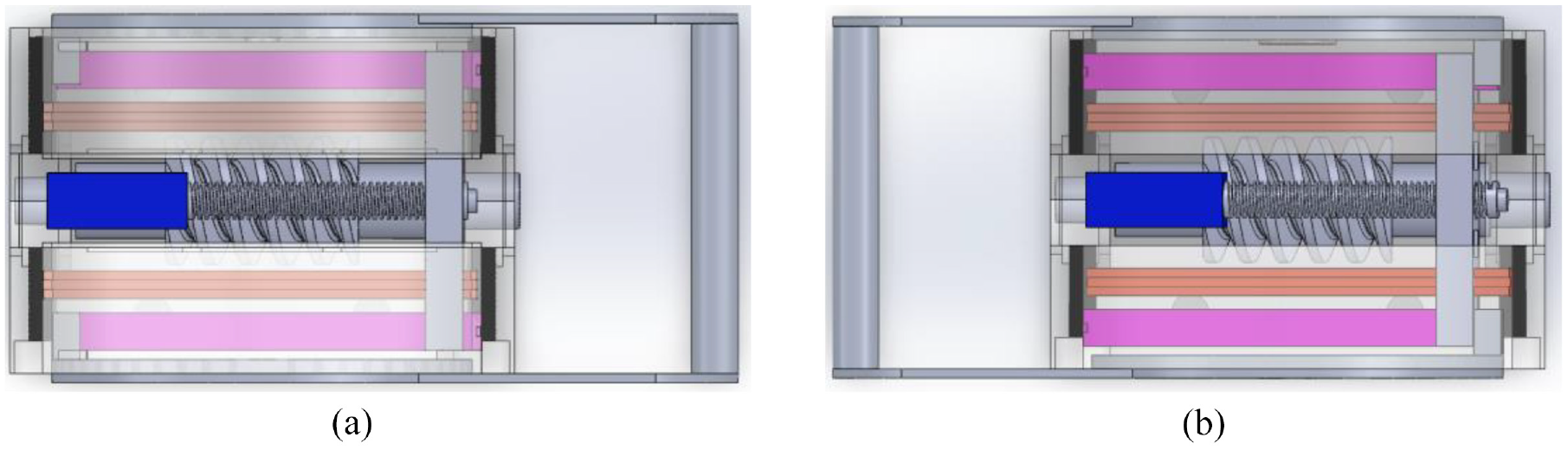
Two design schemes for VSJ: (a) scheme I and (b) scheme II.
Joint parameters.

Theoretical analysis
The joint presented in this paper adopts a variable stiffness lever structure, which is characterized by its simplicity, novelty, and ease of design. The stiffness adjustment principle of the VSJ is illustrated in Figure 5, where only one end needs to be shown due to the symmetrical nature of the joint. The joint design is based on the concept of variable stiffness, allowing for continuous adjustment of stiffness levels. This innovative approach offers several advantages in terms of versatility and adaptability. By utilizing a symmetrical structure, the joint achieves a balanced distribution of forces when subjected to external moments. This balance ensures stability and reduces the likelihood of plastic deformation or excessive strain on the components.

Schematic diagram of stiffness adjustment of VSJ.
Figure 5 provides a clear demonstration of the stiffness adjustment principle employed in the joint design. By manipulating the output angle of the stiffness motor, the effective length of the leaf springs can be modified accordingly. This variation in effective length leads to changes in stiffness, allowing for precise control and flexibility in different applications.
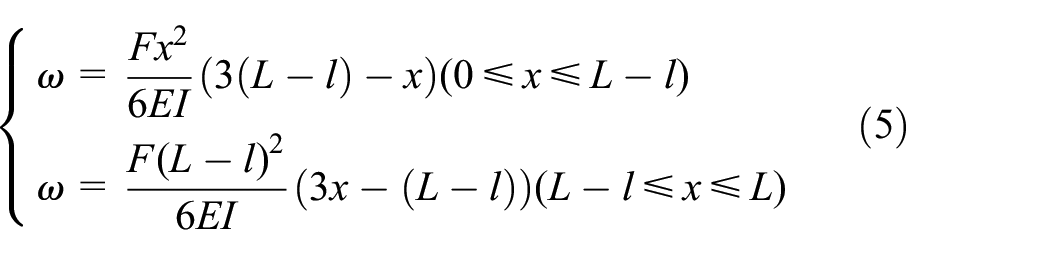
The pivot point can be moved on the leaf springs to change the effective length of the spring. L denotes the total length of the leaf springs from the fixed end to the free end and l denotes the distance from the pivot point to the end of the leaf springs, which is the effective length of the deformed leaf springs. The passive deflection angle of the output axis of the VSJ is Ψ, and the VSJ is mathematically analyzed. The force F acts perpendicularly on the leaf springs when an external moment T is applied. The stiffness K produced by the leaf springs is calculated as follows.

where T is the external moment applied to the output of the joint; Ψ is the angle at which the joint deforms under the external moment.
The external moments and deflections on the output end of the joint are


where F is the force on the free end of the leaf springs; L is the total length of the leaf springs.
The cantilever beam structure has two force points when subjected to concentrated loads. F is the force applied to the end of the spring rod by an external moment of force, equivalent to a concentrated load. FB is the force on the leaf springs at the pivot point when the leaf springs bends at the outer moment. Therefore, the force structure of the cantilever beam can be decomposed into two simple loaded cantilever beam structures.
The deflection of the cantilever beam in Figure 6 is given by

The deflection of the cantilever beam in Figure 7 is given by
where x is any point on the cantilever beam; E is the modulus of elasticity of the spring rod; and I is the moment of inertia of the spring rod in the section with the bending neutral axis under the action of external force;

Concentrated load on the free end of a cantilever beam.

Concentrated load applied at only one point B on the cantilever beam.
When x = L, the deflection at the right end C of the cantilever beam in Figure 6 is

The deflection at point C at the right end of the cantilever beam in Figure 7 is

When x = L−l, the deflection at the right end B of the cantilever beam in Figure 6 is

The deflection at point B at the right end of the cantilever beam in Figure 7 is
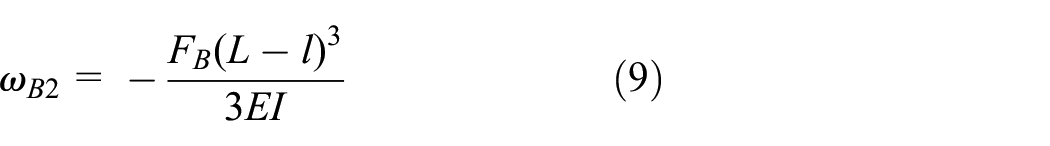
Since the leaf springs is externally loaded with the slider’s constraining force, the deflection is zero at point B. According to the principle of cantilever beam superposition

From equation (9) it follows that FB

According to equations (6) and (10), we can get

And according to the principle of superposition of cantilevers it is known that the deflection at point C gets to be

The selected cantilever beam model has a rectangular cross-section and let the width and height be a and b respectively, then the moment of inertia I is

According to equations (3), (12), and (13), we can get

According to equations (1), (2), and (14), the stiffness K

And the joint structure is symmetric, so the joint stiffness is

From equation (17), the stiffness of the VSJ is related to the material, shape, effective length l, and passive deflection angle Ψ of the node of the leaf springs.
VSJ performance analysis
According to the design parameters of the VSJ and the derived stiffness formula, its performance was analyzed, and the design parameters of the stiffness adjustment system are shown in Table 2.
Design parameters of stiffness adjustment system.
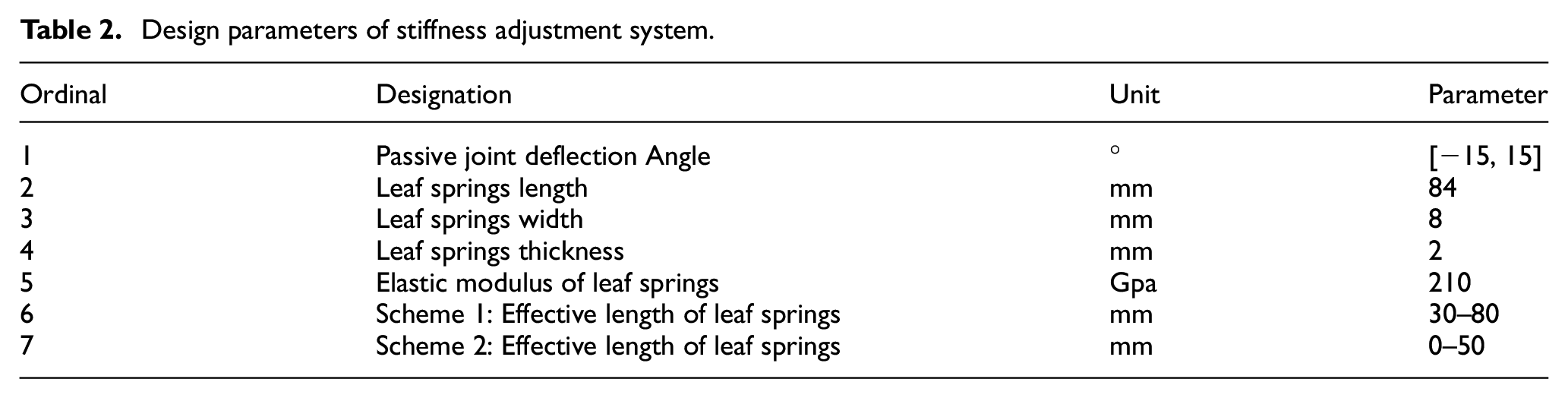
Bringing the parameters of Table 2 into equation (17), the relationship between the node stiffness K and the effective length versus the passive deflection angle can be obtained, as shown in Figure 8.

Nodal stiffness versus effective length and passive deflection: (a) scheme I and (b) scheme II.
As shown in Figure 8, the stiffness of the VSJ depends mainly on the effective length, and the relationship with the passive deflection is not significant. The effective length of the leaf springs is inversely related to the stiffness of the joint, and the stiffness range of the VSJ in Scheme I is [89, 747] in units of Nm/rad; the stiffness range of the VSJ in Scheme II is [251, +∞] in units of Nm/rad. In contrast, the stiffness variation range of scheme I is narrower, while the stiffness variation range of scheme II is wider, which can satisfy the use of rigid joints.
Dynamic analysis of VSJ
Dynamic model of VSJ
In order to study the dynamic characteristics of VSJ, a dynamic model of VSJ needs to be established. This model should take into account various factors, such as the electrical damping and output damping of the motor, the reduction ratio of the turbine worm, and the rotational inertia of each component of the transmission system. This allows the joint dynamic model to more precisely characterize the motion condition of the joint, and to effectively control and reduce the interference of variable stiffness modules on the joint transmission stability.
The VSJ described in this paper are designed with two different assembly schemes, each offering a distinct stiffness range. However, both schemes employ the same components and transmission arrangements, resulting in identical dynamic equations for both. In the subsequent analysis, a detailed examination of the dynamic characteristics of these two assembly schemes will be conducted. Figure 9 illustrates the dynamic model of the VSJ, providing a visual representation of its structure and relevant parameters. For clarity and reference, Table 3 outlines the symbols used in the model along with their corresponding meanings and units.
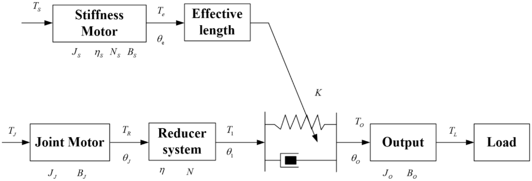
Dynamic model of a VSJ.
The kinetic equations for a VSJ are as follows:
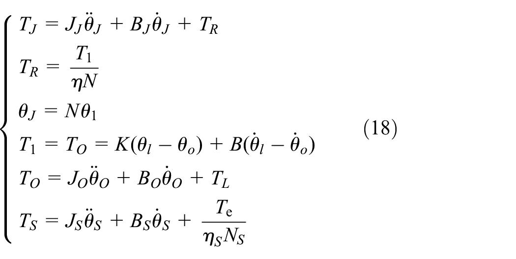
The meanings of various parameters in the VSJ dynamics model.

Dynamic simulation of VSJ
According to equation (18), the visualization block diagram can be built with MATLAB/Simulink, as shown in Figure 10. Assuming that there is no external load on the VSJ, the input torque is the rated torque of the joint motor, the response curves of the joint output angle, angular velocity, and output torque of the two schemes are shown in Figures 11 to 13, respectively, to analyze the changes of the output angle, angular velocity, and torque of the joints under the different stiffness conditions, when the joint stiffness K is changed. The simulation parameters of the VSJ are shown in Table 4.
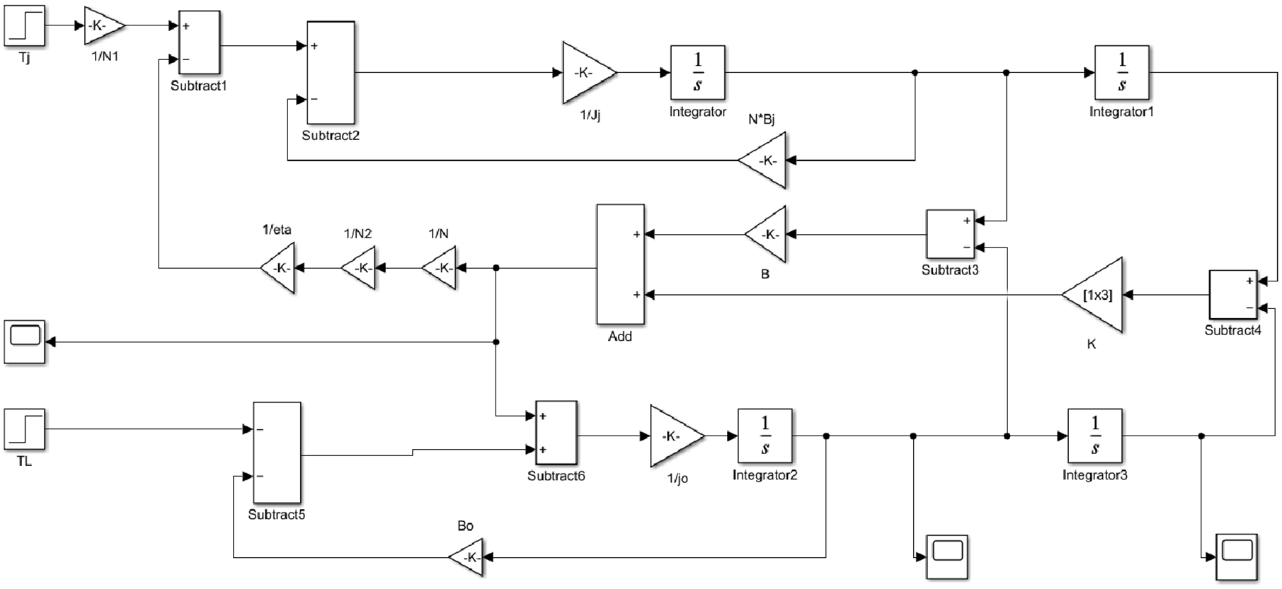
Block diagram for visualization of VSJ.

Response curves for joint output angles: (a) scheme I and (b) scheme II.
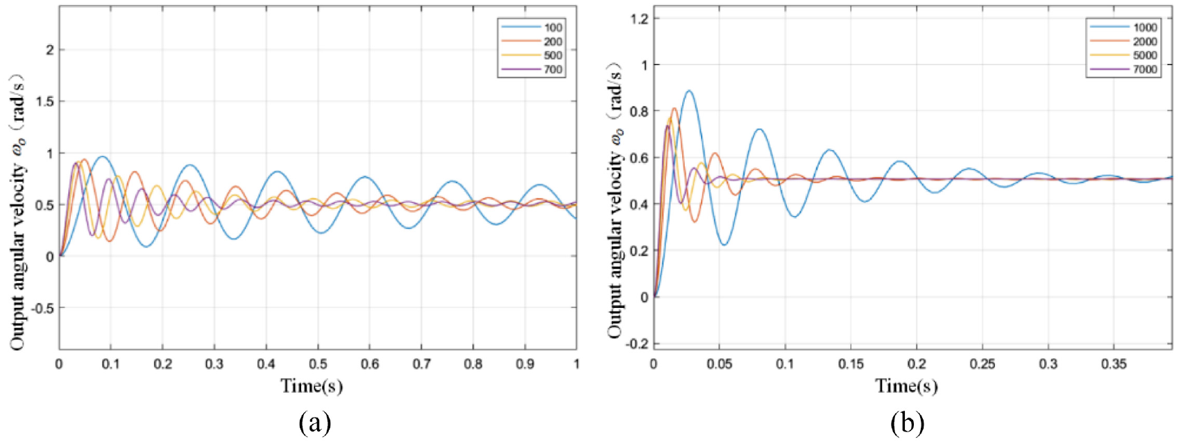
Response curves of the output angular velocity of the joints: (a) scheme I and (b) scheme II.

Response curves of the output torque of the joints: (a) scheme I and (b) scheme II.
Simulation parameters for VSJ.

According to Figure 11, it can be seen that the joint output angle of both schemes is gradually increasing from zero. When the joint stiffness is small, the response curve of the joint output angle with time fluctuates more. When the joint stiffness is large, the curve of the joint output angle with time is close to a linear curve.
As shown in Figure 12, the joint output angular velocities of the two schemes increase from zero and gradually stabilize after a period of time, but there are large fluctuations throughout. The dynamic response of the system varies with the stiffness output state of the joint. When the stiffness is low, the angular velocity fluctuates more sharply and the stabilization time is longer. When the stiffness is higher, the angular velocity fluctuation is smoother and the response is faster.
According to Figure 13, it can be seen that the joint output torque of the two schemes increases from zero to final stabilization, but the whole process presents a large fluctuation.
Then, assuming that the VSJ is subjected to the external load TL = 25 Nm, the input torque is still the rated torque of the joint motor, and observing the response curves of the output torque of the two schemes with respect to time, as shown in Figure 14.

Response curve of output torque with time: (a) original plot of the response curve of output torque with time and (b) local enlargement of the response curve of output torque with time.
Based on the Figure 14, it can be observed that when the VSJ is subjected to a certain load, the output torque gradually increases from zero. Initially, it exhibits an oscillating waveform and eventually stabilizes. Scheme I, with its narrower stiffness range, shows a significantly lower frequency of oscillation compared to Scheme II. In summary, it can be deduced that the output torque fluctuation decreases as the output stiffness of the VSJ increases, and vice versa. However, the response speed does not show significant variation. Additionally, when the external load applied to the VSJ is 25 Nm, the output torque of the joint also approaches 25 Nm. Based on the simulation analysis mentioned above, it can be concluded that the VSJ designed in this paper has achieved the desired design objective.
VSJ stiffness identification and analysis
A static stiffness experiment is a way to measure how the stiffness of a joint changes under a static load. A static load is a load that does not vary with time, or varies very slowly, and does not cause any acceleration or other dynamic effects. Because of the limited lab conditions, only the variable stiffness module of the joint was set up. The goal was to test if the core module could work properly, and confirm that the joint had variable stiffness properties and a range of stiffness adjustment, which would provide data reference for future related control design. Therefore, the specific experimental method in this paper was to use a tensiometer to apply different torques to the output end of the joint, and connect an angle sensor to the PC via Bluetooth, so that the joint deflection angle could be shown in real time. Then, the corresponding joint torque values were calculated. Based on these data, the stiffness behavior of the joint could be analyzed. By using a stiffness motor, the spring could achieve different effective lengths, and multiple stiffness identification experiments were performed for different effective lengths to verify the joint stiffness range. The physical platform is shown in Figure 15.

Experimental platform.
In Scheme I, an effective length of L = 48 mm is chosen by adjusting the stiffening mechanism for the leaf springs. In Scheme II, an effective length of L = 55 mm is selected. Subsequently, multiple stiffness discrimination experiments are conducted for each scheme, and the relevant curves are presented in Figures 16 to 18.

Relationship between joint torque and flexibility angle: (a) scheme I and (b) scheme II.

Comparison of theoretical and measured stiffnesses: (a) scheme I and (b) scheme II.

Relative stiffness error diagram: (a) scheme I and (b) scheme II.
Based on the collected data and the calculated relationship between each joint flexibility angle and joint stiffness, as shown in Figure 16, it can be observed that the internal stiffening structure of the joint remains unchanged. Additionally, there is a strong linear correlation between the joint torque and the joint flexibility angle under different loads. This finding highlights the inherent characteristic of the joint’s structural stiffness, which remains relatively stable when the external loads or flexibility angle are small.
The results indicate that the joint stiffness is primarily influenced by external loads or when the flexibility angle is within a certain range. It is important to note that the stiffness of the joint may vary when subjected to significant changes in external load or larger flexibility angles. These findings provide valuable insights into the behavior and performance of the joint, aiding in its design and application. Further analysis and experimentation can help in fully understanding the extent and limitations of the joint’s stiffness characteristics under various conditions.
Based on the observations from Figures 17 and 18, it can be noted that the measured stiffness and the theoretical stiffness of the joint exhibit similar trends in terms of the slope of the tangent line of the curve when the flexibility angle is small. This suggests that the variable stiffness joint developed in this study possesses a certain level of flexibility. However, as the flexibility angle increases, the difference between the measured and theoretical stiffness values becomes larger. In particular, as the joint stiffness decreases, the stiffness error becomes more significant. Several factors may contribute to these discrepancies. Firstly, differences in the material properties of the actual elastic elements could result in a larger stiffness than expected in the joint. Secondly, errors in the data collection tools used in the experiments may also contribute to the observed differences. Additionally, human error in conducting the experiments or inaccuracies in curve fitting the collected data could introduce discrepancies.
Moreover, friction damping within the joint assembly could also affect the measured stiffness values. Other factors, not limited to the ones mentioned above, might also influence the observed discrepancies between measured and theoretical stiffness. It is important to consider these potential sources of error and further investigate their impact. Addressing these discrepancies will lead to a better understanding of the joint’s behavior and provide insight into potential improvements that can be made to enhance its performance.
Conclusion
This paper presents a VSJ which is innovative in that it employs a worm gear drive to control the joint position, and a sliding screw drive to alter the effective length of the leaf springs. Both drive mechanisms have self-locking features, which can guarantee the safety and stability of the joint stiffness. The joint adopts a symmetrical design, which minimizes the joint size while enabling the joint to have a high stiffness range and a low stiffness range. The theoretical equations for the stiffness of the VSJ are derived in this study. These equations demonstrate that the joint stiffness is primarily dependent on the effective length of the leaf springs, while having minimal correlation with the joint flexibility angle.
We have developed a dynamic model of VSJ and simulated the system in MATLAB/Simulink. The simulation results demonstrate that the VSJ have a certain response bandwidth and good torque and position tracking performance. We have also verified the effectiveness of two assembly schemes of the variable stiffness mechanism by static stiffness experiments. Moreover, we have analyzed and explained the sources of errors in two stiffness tracking experiments. In future research, we aim to apply the VSJ effectively in real scenarios and enhance their transmission stability. Therefore, we will continue to work on finding suitable control strategies and using sensors or encoders for feedback or feedforward control.
Footnotes
Handling Editor: Chenhui Liang
Declaration of conflicting interests
The author(s) declared no potential conflicts of interest with respect to the research, authorship, and/or publication of this article.
Funding
The author(s) disclosed receipt of the following financial support for the research, authorship, and/or publication of this article: Authors would like to acknowledge the support by Doctoral Fund of Henan Polytechnic University (Grant No. B2019-50). Supported by the Outstanding Young Scientists in Beijing (Grant No. BJJWZYJH01201910006021). Open Foundation of the State Key Laboratory of Fluid Power and Mechatronic Systems (Grant No. GZKF-202016). Henan Province Science and Technology Key Project (Grant No. 202102210081, 212102210050). Sub project of strengthening key basic research projects in the basic plan of the science and Technology Commission of the Military Commission (2019-JCJQ-ZD-120-13).