
Abstract
This paper presents the control of a rescue robot driven by the worm-wheel gear transmission. In the modeling process, the load-dependent friction of the worm-wheel gear is considered, and the governing equations for static and dynamic analyses are formulated. Especially we examine the dependency of break-in joint torques on the loading torque and directionality of motion. The friction parameters of the worm-wheel gear of a physical rescue robot are identified through experimental investigation. A friction compensation controller is then designed based on the modeling results and experimental operating conditions. And the designed controller is applied to a dual-arm rescue robot to validate its effectiveness.
Introduction
The worm-wheel gears are one of the most promising options in the electro-mechanical systems for high transmission ratio and energy efficiency.1–4 Contrary to the other types of transmission elements such as bevel and spur gears, where ample space, a large number of gears, and a complex gear train are required to provide the desired gear ratio, the worm-wheel gear requires small space and a single gear set to generate the large transmission ratio.5–8 As a result, worm-wheel gears allow the use of high velocity motors in robotics applications involving slow motion without redirecting the motor torque along a complex gear train. 9 Another potential benefit of a worm-wheel gear is its unique property of self-locking or non-backdrivability that allows it to be driven on the side of input and not back driven on the load side.10–14 Therefore, actuators do not need to stay powered all the time to hold or lift the loads in a particular position. These promising features make the worm-wheel gear transmission a desirable candidate for several robotic applications, including rescue operations.15,16 Compared to the other rescue or field robots such as jumping, snake, and four-flipper robots,17–21 which, used for searching, scanning, and video recording tasks in the disaster areas, are lightweight and can handle small payload, the worm-wheel gear driven rescue robot can hold and manipulate the heavy or oversized payload.
In the worm-wheel gear, the relative movement between the threads of worm and wheel gears is purely sliding, so the performance of worm-wheel gear driven systems are supposed to be affected by the complicated frictional interactions between the worm and wheel gears.22,23 The friction causes nonlinearities that can result in undesired stick-slip motion, tracking errors, and instability in the control of the system.2,24 Unfortunately, there exists only a handful of works reported to the research community to address the relevant issues regarding worm-wheel gear driven systems. A friction model based on a wedge-like planar transmission was introduced by Dohring et al., 25 to address the friction losses of worm-wheel gear driven robots. This friction model consists of implicit parameters in the dynamic equations, although these parameters cannot be directly applied in the controller design. Then, velocity lead–lag and quantitative feedback controllers were proposed in May et al.,26,27 respectively. These are linear controllers and may not be robust enough to deal with the system’s uncertainties. After that, Yeh and Wu 28 proposed a sliding mode controller for friction compensation of the worm-wheel gear, which requires the accurate modeling of the system, knowledge of uncertainty bounds, and worm-wheel gear manufacturing parameters such as worm pitch, pressure angle, coefficient of kinetic frictions, and many other parameters. Their study thoroughly investigated different worm and wheel gear engagement configurations. Despite this study’s significant contributions, it lacked consideration of several crucial issues that arise in practice. First, the response of internal force and coefficient of friction for different loading and velocities is not investigated despite their direct effect on the worm gear’s motion. Second, they perceived the worm-wheel gearbox as a switched system given the friction force dependence on the operating conditions, but the design of control with this assumption has not been proposed. Third, friction torque may cause dynamic switching due to uncertain external factors, and this aspect also has not been considered in controller design. In Homaeinezhad and Adineh 29 the sensorless torque algorithm based on kinetic motion/friction realization is obtained for all kinetic or kinematic configurations of worm-wheel gear. A new method is proposed in Homaeinezhad et al. 30 for worm-wheel gear that is robust to dynamic switching, but it results in a highly sensitive control algorithm that limits its use in real-time mechanical systems. Besides other shortcomings of the previous studies, they were only validated for a customized single-joint worm-wheel gear and may not be directly used to control multi-jointed systems driven by worm-wheel gears due to the high inertia and weight.
The present study is devoted to addressing these undiscovered issues, with examination of a new controller based on the experimental estimation of the worm gear friction parameters, with unknown model uncertainties and external disturbance. More specifically, the main contributions of this paper are:
To estimate the worm gear friction parameters of a rescue robot through experimental investigation;
To propose a friction compensation controller by using the experimentally estimated parameters;
To verify the performance of the proposed controller through experimental investigation.
The paper is organized as follows. In Section “Dual-arm rescue robot driven by worm-wheel gear,” our dual-arm rescue robot driven by worm-wheel gear is introduced; the modeling and control design for the dual-arm rescue robot is covered in Section “Modeling and controller design”; Section “Experimental validation” addresses the effectiveness of the proposed controller. Finally concluding remarks are provided in Section “Conclusion.”
Dual-arm rescue robot driven by worm-wheel gear
Figure 1 shows the dual-arm rescue robot driven by worm-wheel gears developed by the Korea Institute of Machinery and Materials (KIMM) that is under investigation for possible applications for rescue in the field.28,31 (The dual arms are to be attached to a vehicle to move around the field.) This dual-arm rescue robot can carry a payload of approximately 70 kg by the both arms that reach about 95 cm when the arms are fully stretched. It consists of 10 degrees of freedom (DOFs) in total, which are equally distributed among two arms. Each arm of this rescue robot has 5 DOFs and is comprised of pitch

Dual-arm rescue robot driven by worm-wheel gear: (a) hardware diagram and (b) schematic diagram.

Worm-wheel gear actuation module.
DH-parameters of the right arm of rescue robot.


Coordinate system of the right arm of dual-arm rescue robot.
The
Modeling and controller design
Friction modeling of worm-wheel gear
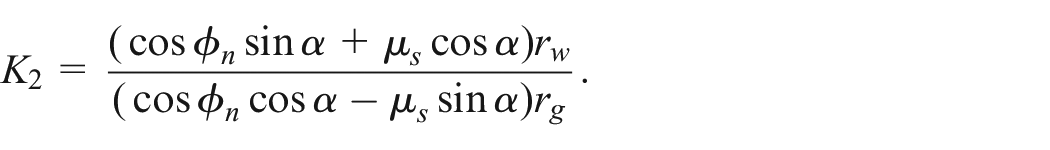
Figure 4 presents the schematic diagram of a worm-wheel gear transmission, where

Schematic of the worm and wheel gears engagement: (a) left side engagement and (b) right side engagement.
Figure 5 shows the schematic force diagram of the former two cases of engagement, where the force exerted on the worm by the wheel gear consists of a friction force


Force diagram of the worm-wheel gear engagement: (a) left side engagement and (b) right side engagement.
among which

where

where
Similar force analysis can be carried out for the case with right side engagement (Figure 5(b)). The resulting dynamic equations for the worm and wheel can be written as

and

Note that the only difference in the dynamic equations of the left and right sided engagements is the different direction of the friction force
Self-locking condition: For the worm-wheel gear, the static state (i.e. self-locking) occurs, if the relation between

where
Dynamic condition: It is said that the worm gear is in the dynamic condition when it is not in the self-locking state. If so, the friction between worm and wheel gears could be written as

where

where

where

and
The dynamic equation for
As compared to the value of wheel inertia

From above, four possible dynamic modes exists depending on the direction of the joint and the left or right engagement of the worm-wheel gear. Therefore, it is better for precise control to employ a proper mode of the dynamics based on the current state and the loading condition.
Note that the rescue robot is not intended for high speed tasks. Thus, the inertial reaction among the joints can be neglected, so that most part of
Worm gear friction parameters estimation
In the quasi static condition, where the velocity and acceleration is negligibly small, the worm-wheel gear,

where
For this purpose, we deployed the rescue robot for experimental investigation. For a fixed
Note the load dependent friction model (13) does not have a constant offset friction although most practical mechanical joints are likely to possess. The joint with a worm-wheel gear can also be one of those. So, for a better regression accuracy, a modified model for the quasi static joint torque can be used as

where
Figure 6 shows the measured break-in torques for the first three joints in the right arm (i.e.

Experimental results for the break-in torque of dual-arm rescue robot joints
Where the blue dots
Identification of linear regression model coefficient by least square method.

Controller design
The friction compensation controller of each joint is proposed by using the linear regression model in (13) as follows.
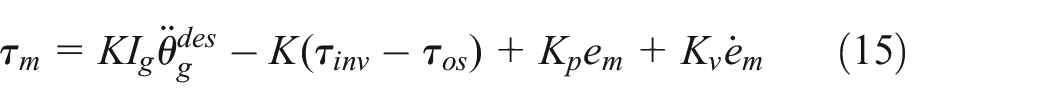
where
The inverse torque of the robot,

where
Experimental validation
The experimental investigation aimed to verify the effectiveness of our proposed friction compensation control scheme. The performance of the proposed controller was evaluated by using the following performance evaluation index:
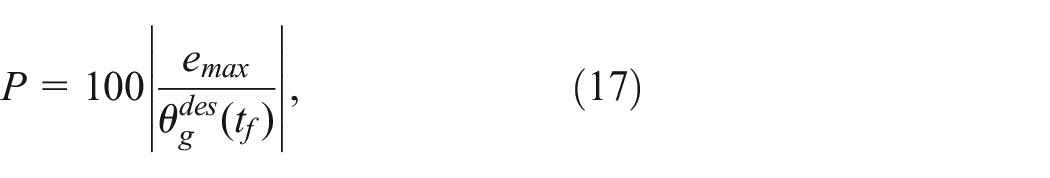
where
Experimental setup
The dual-arm rescue robot shown in Figure 1 was employed for the experiments. As mentioned earlier, the first three joints,
For the software implementation, we patched Real-Time eXtension (RTX) over Windows XP and deployed it on an IBM PC (Intel Core i5 CPU). RTX from IntervalZero is a real-time extension for Windows and enables the timer to interrupt with the highest priority, with a maximum latency of only 12 µs. The operating frequency of the control algorithm was 1000 Hz. The effectiveness of the proposed controller was verified by laboratory tests. In the future, field experiments in an open field will be conducted.
Tracking control for dual-arm rescue robot
To demonstrate the effectiveness of the proposed friction compensation control scheme, we compared the tracking performance of the proposed controller in (15) with that of the conventional proportional and derivative control without any additional action (PD-only) controller, which is of the form:
A set of experiments was conducted to evaluate the performance of the proposed controller in both upward and downward directions of the joints motion, in which the joints of the dual-arm rescue robot had to follow a reference trajectory that traveled

Configurations of the dual-arm rescue robot. (a and b) initial/terminal configurations for a small-range trajectory and (c and d) initial/terminal configurations for a large-range trajectory: (a) config(
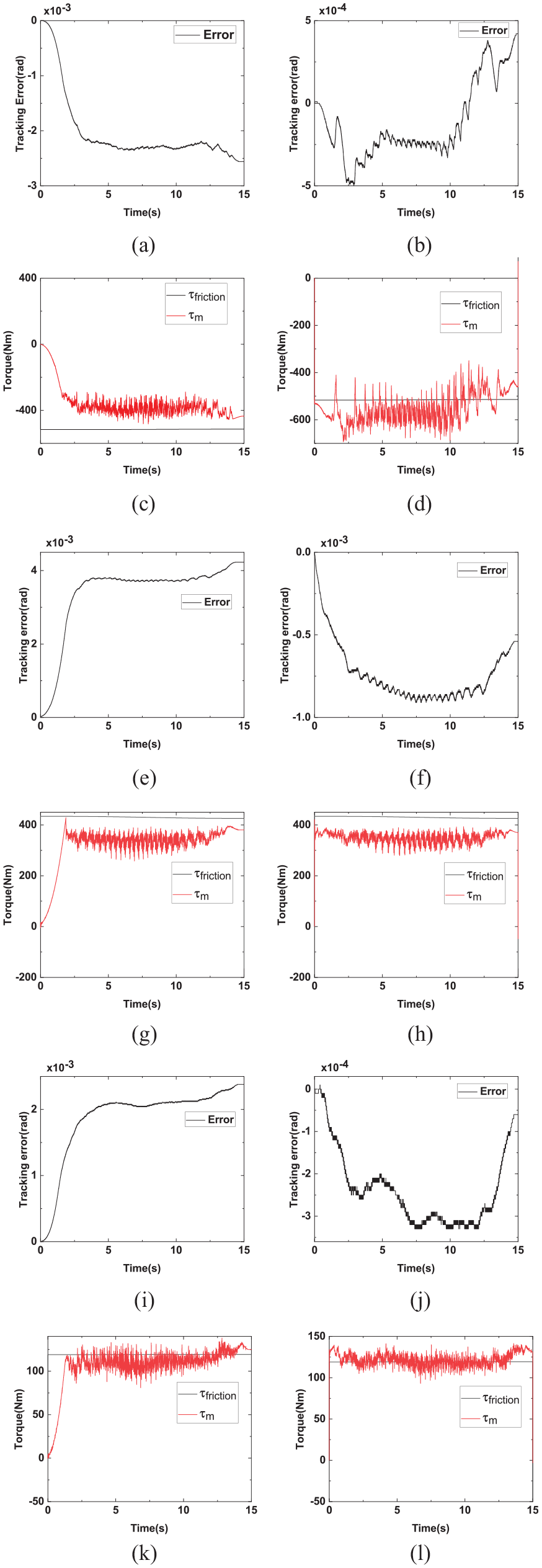
Experimental results using the PD-Only and proposed controllers for 5° upward joint motion: Trajectory tracking and Required Torque for Joints R1 (a to d), R2 (e to h), and R3 (i to l) with PD-Only (left) and Proposed (right) Control Techniques.

Experimental results using the PD-Only and proposed controllers for 5° downward joint motion: Trajectory tracking and Required Torque for Joints R1 (a to d), R2 (e to h), and R3 (i to l) with PD-Only (left) and Proposed (right) Control Techniques.
Referring to the Figures 8 and 9, the overall tracking performance of the PD-only controller fell significantly behind the proposed controller. In most of the joint responses, the tracking errors by the PD-only controller were larger by an order than those by the proposed controller. The main reason for this behavior might be the uncontrolled friction in the worm-wheel gear driven joints. Any increase in controller gains of PD-only controller to minimize the trajectory tracking error tended to excite the system instability. Once the proposed friction compensation controller was applied, the overall control tracking performance was improved. The performance evaluation indexes indicated the effectiveness of the proposed controller; they were improved by 5.1, 4, and 7 times during the upward movements and 2.5, 2.3, and 7.7 times during the downward movements for the joints
Next, we carried out another set of experiments to evaluate the performance of the proposed controller with the same experimental setting, except reference trajectory was extended to

Experimental results using the PD-Only and proposed controllers for 90° upward joint motion: Trajectory tracking and Required Torque for Joints R1 (a to d), R2 (e to h), and R3 (i to l) with PD-Only (left) and Proposed (right) Control Techniques.

Experimental results using the PD-Only and proposed controllers for 90° downward joint motion: Trajectory tracking and Required Torque for Joints R1 (a to d), R2 (e to h), and R3 (i to l) with PD-Only (left) and Proposed (right) Control Techniques.
A large amount of additional experiments was conducted to further compare the averaged performance of the proposed controller with that of the PD-only control different travel ranges, speeds, and directions of joints motion. The performance evaluation indexes of experimental tests with the PD-only controller and the proposed friction compensation controller are shown in Figure 12. The experimental results showed the effectiveness of the proposed controller with improved performance evaluation indexes in all the cases due to the worm gear friction compensation. Among the results, better performance enhancement tended to be obtained when the robot motion was given in the upward direction than in the downward direction. Specifically, the improvement in the performance evaluation indexes of joints motion was relatively small in some cases, such as the tracking results of
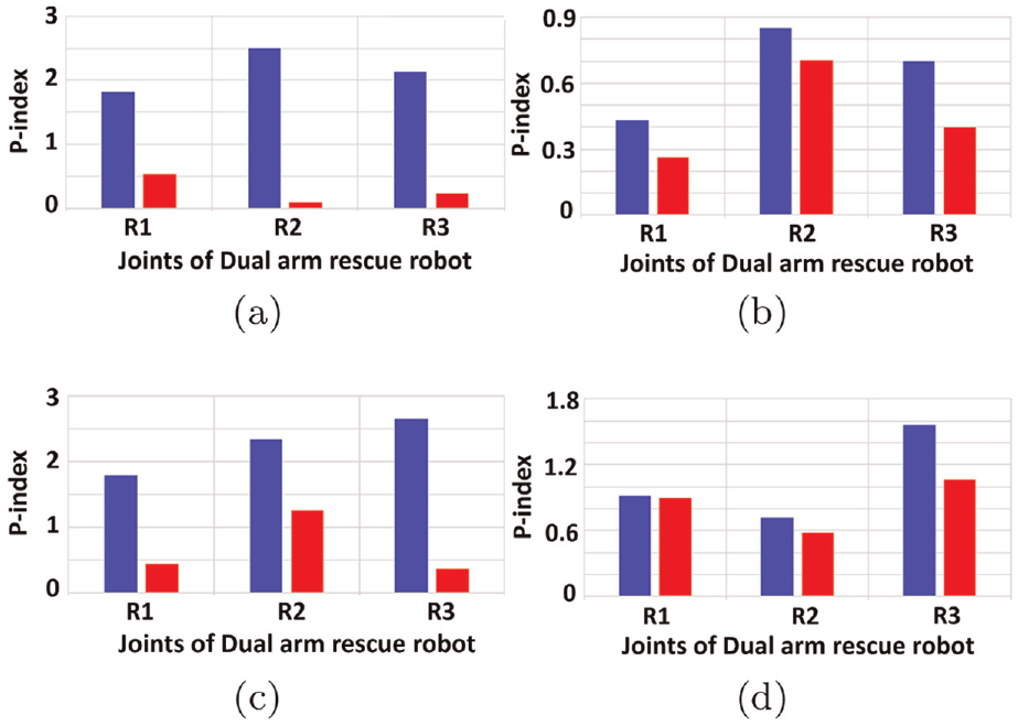
Performance evaluation indexes of experimental tests with the PD-only controller (red color) and the proposed friction compensation controller (blue color): (a) travel range
Hence, these experimental results show that the proposed friction compensation controller is effective and capable of reducing the trajectory tracking error in worm-wheel gear driven joints of dual-arm rescue robot.
Conclusion
Previous friction compensation controller for worm-wheel gear driven system required accurate modeling of the system, knowledge of uncertainty bounds, and worm-wheel gear parameters such as pressure angle, coefficient of kinetic frictions, worm radius, wheel gear radius, speed ratio, and the steady state torque ratio. However, it may be challenging to find this information about the commercially or off the shelf available worm-wheel gear. This paper introduced a friction compensation control for the dual-arm rescue robot driven by commercially available worm-wheel gears, with unknown worm-wheel gear friction parameters and uncertainties. This paper has three distinct contributions: (i) the worm-wheel gear friction parameters of a worm-wheel gear driven dual-arm rescue robot were identified through experimental investigation, (ii) a friction compensation controller was then designed based on the modeling results and experimental operating conditions, (iii) the proposed control technique was applied to a dual-arm rescue robot and experimental results indicated the proposed control system exhibits significant improvement in trajectory tracking control in both slow and fast motions.
Footnotes
Handling Editor: Chenhui Liang
Declaration of conflicting interests
The author(s) declared no potential conflicts of interest with respect to the research, authorship, and/or publication of this article.
Funding
The author(s) disclosed receipt of the following financial support for the research, authorship, and/or publication of this article: This work has been supported partly by the Energy Efficiency and Resources of the Korea Institute of Energy Technology Evaluation and Planning (KETEP) grant (No. 20202020800020) funded by the Ministry of Trade, Industry and Energy (MOTIE), partly by the National Research Foundation of Korea (NRF) grant funded by the Korea government (NRF-2021R1A2C1095085), and partly by the Korea University grant.
Consent to participate
The authors agree to participate.
Consent for publication
The authors consent to publish.
Availability of data and material
All data used in this work will be presented upon reasonable request.