
Abstract
The square fin was used to improve the heat transfer rate of the concentric tube phase change heat exchanger. The effects of fin spacing, fin arrangement, and fin length on the melting process of phase change material (PCM) were studied. The influence and mechanism of non-uniform fin arrangement were discussed in detail. The liquid phase distribution and temperature distribution of PCM with time were analyzed. The results indicated that the heat exchanger with square fins can significantly improve the heat storage rate and shortened the complete melting time of PCM. Compared with heat exchangers without fins, the melting time of PCM in a 40 mm equidistant fin heat exchanger was shortened by 15.85%, and that in a 70 mm, non-uniformly spaced fin heat exchanger was shortened by 36.79%. Due to the different distances between the square fins and the outer boundary of the concentric tube, the temperature distribution near the square fin showed anisotropy, which enhanced the melting rate of PCM. The sensitivity order was fin arrangement > fin length > fin spacing. The research results can provide a reference for the design of phase change heat exchangers.
Keywords
Introduction
With the increasing proportion of new energy generation and the increasing depth of peaking of thermal power generation, the contradiction between supply and demand in energy is becoming increasingly prominent, and energy storage technology has become a research hotspot.1,2 Phase change heat storage technology has a broad application prospect in the field of new energy development and low load operation regulation of thermal power units, and shell-and-tube accumulator is a phase change heat storage device with high application potential.3–5 However, due to the small thermal conductivity and poor heat transfer performance of PCM, the performance and application range of phase change heat storage are greatly limited. 6 The installation of fins or optimization of the structure of the storage heat exchanger can strengthen the heat transfer process of PCM and solve the problem of low thermal conductivity of PCM.7–9
Many scholars have studied the heat transfer performance of heat exchangers with different fin shapes. Rauber et al. 10 optimized the fin structure of a four-tube heat exchanger with rectangular and circular perforations in the center of the fins and showed that a larger characteristic perforation size increases the heat transfer rate of the heat exchanger. Kumar et al. 11 analyzed the effect of concave fins on heat transfer and fluid flow in heat exchanger tubes, and improved fluid disturbance by changing the depth of the concave rib, spacing and span of the concave fins. The results showed that the concave fins increase the roughness of the heat transfer surface relative to the smooth conventional heat exchanger, resulting in a 3.18 times improvement in heat transfer performance. El Ghandouri et al. 12 proposed to replace smooth fins with corrugated fins to improve convective heat transfer in the heat sink and reduce its weight. The fin reduces the temperature at the bottom of the radiator by 18.35 K and increases the heat transfer coefficient by 101.41% compared to conventional fins. Irbai’ and Najjar 13 enhances latent heat transfer by a forked dispersion structure, and the PCM in the heat exchanger melts completely within 900 s due to the increase in the heat transfer area of the heat exchanger. Sun et al. 14 optimized the design of a topological fin structure heat exchanger to increase the heat transfer area on the air side. As a result, they achieve a 7.0% increase in heat dissipation and a 33.3% reduction in fan power compared to the unoptimized structure. Zhang et al. 15 developed a new fin heat exchanger with double spiral fins embedded in the phase change material region to reduce the phase change time of the PCM.
Some scholars have studied the influence of fin size and number on heat transfer performance of heat exchangers. Talukdar et al. 16 studied a latent heat exchanger consisting of an evaporator tube equipped with PCM and rectangular metal fins, and studied the influence of the number and thickness of longitudinal aluminum fins on heat transfer. Amer et al. 17 investigated the effect of the number of circular fins on heat transfer with the same fin volume, and the results showed that fins can enhance the heat transfer effect, and there is an optimal number of fins. Shahsavar et al. 18 investigated the effect of fin diameter on the phase change process in a double-tube latent heat storage system, stating that increasing the fin diameter up to a certain point can have a detrimental effect due to the inhibition of natural convection effects.
It can be seen from the above research that fins have a great influence on the performance of heat exchangers.19–23 The shape of fin is the focus of research, but the special shape of fin will greatly increase the cost of manufacturing. There are few studies on fins with unequal spacing. It should be noted that, during the phase change process, natural convection occurs due to gravity. This natural convection can enhance the heat transfer of the heat storage exchanger. When longer fins are used to increase the thermal conductivity of the heat storage exchanger, it is important to consider the potential inhibition of natural convection effects. Inhibiting natural convection may adversely affect the overall heat transfer performance.
The paper proposed to add square fins to the phase change material side of the shell-and-tube heat storage exchanger to enhance the heat storage rate. The effect of square fins on the heat storage rate of concentric circular tube heat exchanger was studied. The influence of fin spacing on the heat storage performance was studied for the uniformly spaced fin arrangement. The evenly spaced fin arrangement was compared with the non-uniformly spaced fin arrangement. The influence effect and mechanism of unequal spacing fin arrangement were deeply discussed. The research results can provide reference for the design of shell-and-tube heat exchanger.
Modeling
Geometric model
In this paper, the temperature and liquid phase ratio in various parts of the heat storage exchanger were studied from different directions by 3D models. The natural convection effect of the liquid phase material after the phase change was considered. Continuity equation, momentum equation, and energy equation were used as controlling equations of the phase change process. The heat storage exchanger is an annular concentric cylinder with stainless steel plates on the inner and outer walls of the tube, the upper and lower surfaces and the fins. Considering the influence of gravity, the accumulator is placed vertically. The line of action of gravity passes through the center line of the cylinder. The finned arrangement of the optimization model is shown in Figure 1. The water in the heat storage tube as the heat transfer fluid (HTF), the flow direction is from bottom to top. The annular space is the phase change material paraffin, and the relevant physical properties are shown in Table 1. The tube height is 315 mm, the outer diameter of outer tube is 126 mm, the inner diameter of inner tube is 25 mm, the wall thickness and fin thickness are both 3 mm, and the water flowing inside the inner tube heats the PCM between the inner and outer tube.

Optimization model after installation of fin.

Considering the height and size of the heat exchanger, the models with fin edge length of 50 mm, uniform fin spacing of 50, 45, 40 mm, and non-uniform fin spacing were selected as the research object. The influence of different finned heat exchangers on the melting process was studied. Figure 2 shows the fin models with different spacings. The spacing of the non-uniform spacing model is shown in Figure 2(e). The first spacing is 62 mm, and the total number of fins is 7, which is the same as the number of 40 mm uniform spacing fins model.

Fin models with different spacing: (a) 50 mm spacing, (b) 45 mm spacing, (c) 40 mm spacing, (d) non-uniformly spacing, and (e) value of non-uniformly spacing.
Mathematical model and solution method
The enthalpy-porous medium model was used in the solidification/melting model to simulate the phase change in PCM. The following assumptions were made to facilitate the calculations:
Liquid phase paraffin was incompressible Newtonian fluids;
Paraffin wax was pure and thermally isotropic;
The liquid phase paraffin waxes flowed laminar, ignoring viscous dissipation;
The variation of paraffin density with temperature was small, following Boussinesq hypothesis and considering only the effect of buoyancy force;
The outer tube wall surface and upper and lower surfaces were adiabatic from the outside.
The natural convection of PCM in the computational domain was considered through the Boussinesq approximation, and the basic equations for the calculation in the model included the continuity equation, the momentum equation, and the energy equation.
Continuity equation:

Where:
Momentum equation:

Where:
In the HTF calculation domain,

The solid-liquid paste phase region was regarded as the porous media region, where the liquid phase ratio β varied between 0 and 1.
Where:

Where:
Energy equation:

Where:
In the HTF calculation domain, SL = 0. In the PCM region,

The enthalpy H of the material was calculated by the sensible heat and the latent heat:

Where:
The outer wall and upper and lower surface of the heat storage exchanger were set as an adiabatic interface.
Where is outer wall boundary conditions:

A SIMPLE algorithm was used for the iterative solution process. Pressure corrections used PRESTO! format. Energy and momentum equations were discretized by second-order windward difference format. The initial temperature of the HTF was set to 303.15 K and the fluid inlet velocity was 0.35 m/s. The grid-independent validation results are shown in Figure 3. It can be seen that the temperature difference between the monitoring points for the five body grid sizes is small, and the smaller the mesh size, the more accurate the calculation result. Considering the increase in computation time due to the reduction of the grid size, a relatively small body grid size of 2.6 × 10⁵ was used for the subsequent simulations.

Temperature curves of monitoring points with time under different grid sizes.
Regarding the selection of the time step, numerical simulations of the monitoring point were performed for the cases of time step sizes 0.1, 0.2, and 0.5 s, respectively, to compare the temperature of 5000 s. As shown in Table 2, the calculation results of different time step sizes do not differ much, but a smaller time step size will significantly increase the computation time. After comprehensive consideration, the time step size of 0.5 s was finally chosen for the subsequent numerical calculations.
Calculation error and time consuming of different time steps.

Model validation
To verify the validity of the model and numerical calculation results, the monitoring point 2 (the location of the corresponding point in this paper is 215 mm in the cylinder height direction and 23.5 mm from the outer wall of the inner tube) experimentally studied by Liu 24 was selected as the model verification in this paper. Figure 4 is the comparison diagram of temperature change curve with time at this point between reference experiment and simulation study. Compared with the experimental results, the melting rate is slightly slower at the beginning stage and slightly faster at the later stage. The complete melting time of the phase change material obtained by the two methods is about 500 min. The simulation study is carried out under ideal conditions. There are many interference factors in the actual measurement, and the difference within a certain error range is acceptable. The numerical calculation model established in this paper is reliable.

Temperature curve of monitoring point with time.
Results and analysis
In this study, square fin groups with different sizes and spacing were installed to strengthen the heat transfer of the heat accumulator. The influence of fin spacing and edge length on the overall heat transfer effect of the heat accumulator was studied. Because the change curve of liquid phase ratio with time was gentle at the last stage of melting, and the PCM at the bottom was the last to melt under the action of natural convection, it was proposed to arrange the fins densely along the gravity direction to further increase thermal conductivity. Due to the volume of fins in the heat accumulator was small, the influence of fin volume difference on the liquid phase ratio calculation results of each model was ignored.
Influence of fin spacing on heat storage process
The inlet temperature of the fluid in the pipe is 343.15 K, and the initial temperature of the PCM is 303.15 K. Figure 5 shows the change of liquid phase ratio of non-fin heat exchangers and four kinds of fin heat exchangers with time. It can be seen that the addition of fin can greatly improve the heat transfer rate, especially in the early stage of melting. The complete melting time of phase change material without fin heat exchanger is 492 min, and the liquid phase ratio curve changes gently with time. For the three kinds of heat exchangers with equal spacing of 50, 45, and 40 mm, the liquid phase ratio at the early melting stage (liquid fraction <0.8) increases successively. Three equally spaced models with intervals of 50, 45, and 40 mm take 448, 417, and 414 min to finish the phase transition, indicating that the more densely spaced fin group models have faster heat transfer speed and shorter time to complete the phase transition. The addition of fins is equivalent to increasing the thermal conductivity of the heat storage material. The heat transfer effect of the three equally spaced fin models is better than that of the non-fin model. The best heat transfer model is the fin model with 40 mm spacing, and the melting process is shortened by nearly 15.85% comparing with the no fin model. The fins are stainless steel materials, they have relatively high thermal conductivity. In a certain range, the relatively dense fin arrangement improves the heat transfer rate between HTF and PCM, thus shortening the complete melting time of PCM.
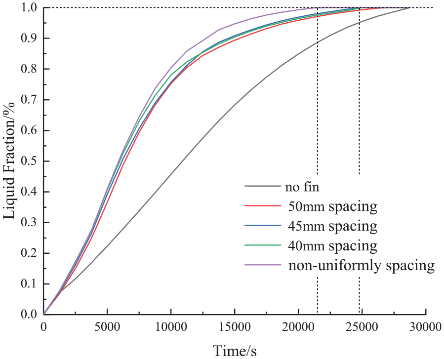
Change of liquid phase ratio with time.
For densely arranged fin heat exchanger in the direction of gravity, the number of fins is the same as that of fin heat exchanger with 40 mm spacing, which is seven. As can be seen from Figure 5, the phase transition time with the non-uniformly spacing fins is only 358 min, which is 56 min faster than that of the fin heat exchanger with equal spacing of 40 mm. Based on the complete melting time of the finless heat exchanger, the melting process is shortened by 11.39%. Compared with uniform fin arrangement, the dense fin arrangement in the lower part strengthens thermal conductivity of low temperature PCM in the lower layer and decreases the difference in heat transfer effect between the upper and lower layers. The complete melting time of PCM is shortened.
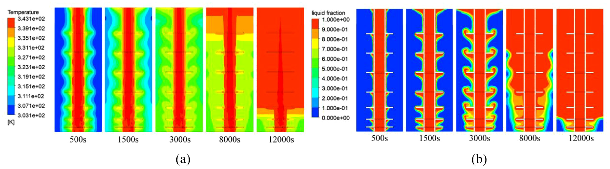
Figure 6 shows the temperature distribution and liquid phase ratio distribution of PCM in heat exchangers without fins and with 50 mm spacing fins. As can be seen from Figure 6(c), the temperature of PCM near the fin is relatively high and the fins play the role of heat conduction. Compared with Figure 6(a), it shows that the high temperature zone in the heat accumulator increases at the same time node. It can also be seen from Figure 6(b) and (d) that after the installation of fin, the liquid phase distribution at the same time is wider. The fins accelerate the melting rate of PCM.

Temperature distribution and liquid phase ratio distribution of PCM (a and b) no fin (c and d) 50 mm spacing fins.
Effect of fin edge length on heat storage process
The fin model with dense arrangement at the bottom greatly reduced the melting time of PCM. To further improve the heat transfer effect, based on the non-uniformly spacing fin group in Figure 2(d), the fin heat exchangers with fin lengths of 50, 60, and 70 mm were compared. Figure 7 is the change curve of liquid fraction with time under different fin lengths.

Change of liquid phase ratio with time with different fin lengths.
It can be seen that long fin can further enhance heat transfer. The heat transfer time of 50, 60, and 70 mm fin models is 358, 347, and 311 min, respectively. The complete melting time of 70 mm fin heat exchanger is 47 min shorter than that of 50 mm fin heat exchanger. In a certain range, lengthening the fin length can further improve the heat transfer effect. Compared with no fin, the melting time of phase change material with 70 mm fin is shortened by 36.79%.
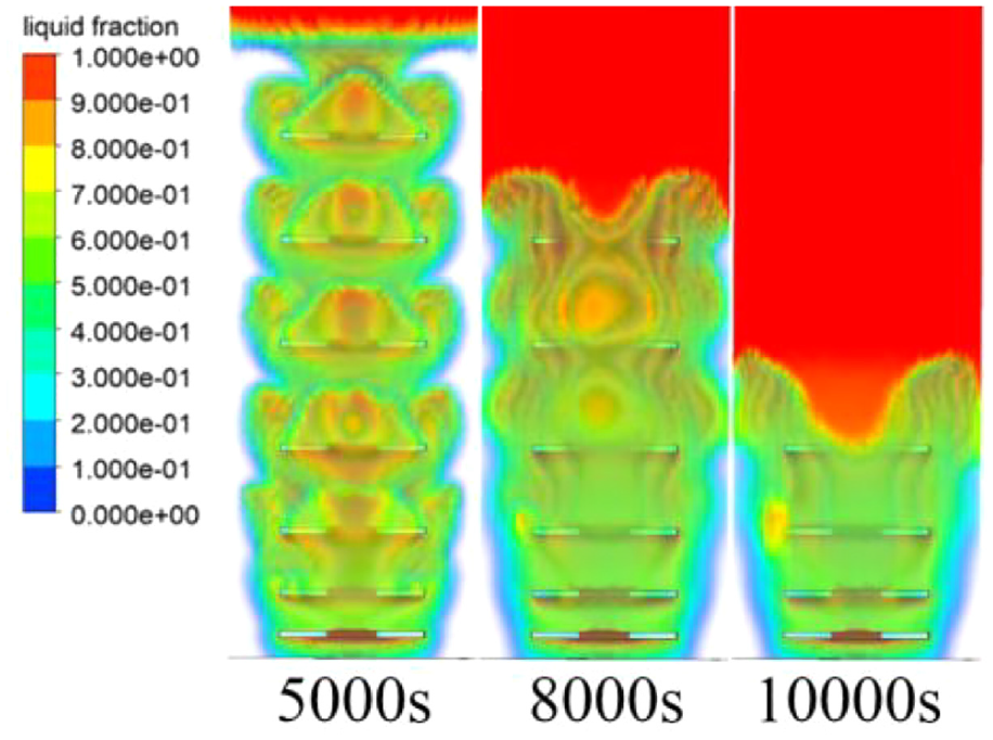
Figure 8 shows the temperature distribution and liquid phase ratio distribution of a finned heat exchanger with a fin length of 70 mm. It can be seen that the fin extends to the depth of the PCM, which makes the PCM near the outer wall melts faster, thus further shortening the complete melting time of PCM. This indicates that for this type of tube and shell heat exchanger, within a certain range, the increase of fin length is beneficial to accelerate the melting process and improve the heat transfer effect.
Temperature distribution and liquid phase distribution of 70 mm fin model: (a) temperature distribution and (b) liquid phase ratio distribution.
Analysis of heat transfer effect at different positions of square fins
Due to the different extension lengths of each part of the square fin in the PCM, the heat transfer effect of square fin at different positions is different. Figure 9 shows the cross-section cloud diagram of the 70 mm fin heat exchanger in the diagonal direction. Compared with Figure 8(a), the heat conduction distance of the four corners is longer than that of the straight edge. The cloud map of temperature and liquid distribution in different directions shows anisotropy. Similar to the research mechanism on the influence of fin length on heat transfer, the longer the heat conduction distance at the four corners of the fin, the more favorable the heat conduction effect in the whole heat exchanger.

Temperature distribution and liquid phase distribution in the diagonal section of the 70 mm fin model: (a) temperature distribution and (b) liquid phase distribution.
Figure 10 is a 3D frontal view of liquid phase distribution of the 70 mm fin model. The three-dimensional distribution of the liquid phase can be visually observed in this figure. It can be found that the PCM near the straight edge of the fin melts earlier than the PCM at the four corners. The reason for this phenomenon is that the depth extending from the straight edge of the fin is shorter than the depth extending from the corners, and the blocking effect on the natural convection caused by the change of the upper and lower density is less. Compared with the four corners, the flow of the two phases is promoted and the heat transfer is strengthened, and the melting speed of PCM is higher than that at the corners. The good melting condition also benefits from the heat conduction from the four corners of the square fin. The four corners of the fin extend deeply, so that the temperature at the same height can reach the phase transition condition, which promotes the natural convection near the straight edge of the fin.
3D liquid phase distribution of the 70 mm fin model (straight side face).
Sensitivity analysis
Table 3 shows the sensitivity of fin structure parameters to the complete melting time. It is based on the complete melting time of the finless heat exchanger, the change rate of the complete melting time of finned heat exchangers of different structures is given. It can be seen from the table that the complete melting time of PCM is greatly shortened after the addition of fins. When the equally spaced fins are added and the fin length and spacing are 50 mm, the complete melting time of PCM is shortened by 8.94%.
Sensitivity of fin structure parameters to the complete melting time.

The effect of fin spacing
The fin length is 50 mm, the fin spacing is changed. The complete melting time of the PCM at 45 mm spacing is 6.30% shorter than that at 50 mm spacing. When the fin spacing is further reduced to 40 mm, the complete melting time is only 0.61% less than that at 45 mm spacing. After the fin spacing is reduced to a certain distance, further reducing the fin spacing can reduce the complete melting time, but the effect is very limited. Because the addition of fins reduces the volume of PCM, and then affects the heat storage of PCM, the appropriate fin spacing should be selected in practical applications.
The effect of fin arrangement
The fins are 50 mm long and the number of fins is seven. The fin arrangement is changed. The fins are densely arranged along the direction of gravity. Compared with the heat exchanger with equal spacing of 40 mm, the full melting time of PCM is shortened by 11.39%. Due to the synergistic effect of heat conduction and convective, the arrangement of fins densely arranged along the direction of gravity greatly reduces the complete melting time of PCM.
The effect of fin length
A heat exchanger with dense fins in the direction of gravity is used, and only the length of the fins is changed. The complete melting time of 60 mm fin is 2.23% shorter than that of 50 mm fin, and the complete melting time of 70 mm fin is 7.32% shorter than that of 60 mm fin. It shows that the fin length has great influence on the complete melting time, which should be paid attention to in practical design.
In summary, the sensitivity order is fin arrangement > fin length > fin spacing.
Comparative study of heat exchangers at different Reynolds numbers
The complete melting time of PCM is used as the criterion for the design. In order to study the performance of the heat exchanger proposed in this paper, two typical heat exchangers with different fluid flow velocity are compared. One is a traditional finless heat exchanger, and the other is the heat exchanger with densely arranged fins in the direction of gravity, and the fin length is 70 mm. The fluid flow rates are 0.15, 0.25, and 0.35 m/s. The corresponding Reynolds numbers are 3750, 6250, and 8750, respectively. The research results are shown in Figure 11. It can be seen that the larger the Reynolds number, the stronger the disturbance, and the shorter the complete melting time of PCM. Compared with traditional finless heat exchanger, the heat exchangers with fins densely arranged along the gravity direction can effectively shorten the complete melting time of PCM at different Reynolds numbers.

Performance comparison of two heat exchangers at different Reynolds numbers.
Conclusions
In this paper, the three-dimensional numerical simulation of the phase change heat transfer process in the square-finned concentric tube heat storage exchanger was carried out. The effect of the square fin on the heat storage rate of the concentric circular tube heat exchanger was studied. The influences of fin spacing, fin arrangement, and fin length on the melting process of PCM were simulated and analyzed. The influence effect and mechanism of unequal spacing fin arrangement were discussed in depth. The main conclusions are as follows:
In the optimization of concentric tube accumulator model, the addition of fin can greatly improve the heat storage rate and shortened the complete melting time of PCM. The sensitivity order was fin arrangement > fin length > fin spacing.
In a certain range, the complete melting time of PCM decreased with the decrease of fin spacing and the increase of fin length. The complete melting time of PCM with densely arranged fins in the direction of gravity was shorter than that with uniformly spaced fins.
In the case of uniform spacing arrangement, the fin group model with 40 mm spacing arrangement had the best comprehensive heat transfer effect. The complete melting time was 15.85% shorter than that of no fin model. The smaller the fin spacing was, the higher the overall heat transfer rate was.
The heat transfer effect was further improved for the model with densely arranged fins along the gravity direction. The heat storage time of the 70 mm length fin model was the shortest, and the complete melting time was shortened by 36.79% compared with that of no fin model.
Due to the different extension lengths of the square fin, the temperature distribution of PCM near the square fin angle and the straight edge was anisotropic. The temperature difference played a synergistic heat transfer effect. The square fin is suitable for the concentric tube phase change heat storage exchanger. The research of this paper can provide reference for the design and application of phase change heat storage exchanger.
Footnotes
Handling Editor: Chenhui Liang
Declaration of conflicting interests
The author(s) declared no potential conflicts of interest with respect to the research, authorship, and/or publication of this article.
Funding
The author(s) disclosed receipt of the following financial support for the research, authorship, and/or publication of this article: This research is supported by the Science and Technology Commission of Shanghai Municipality under the contract No. 20dz1205208, which is gratefully acknowledged by the authors.