
Abstract
Solar air heating is a solar thermal technology wherein the sun energy is absorbed by an intermediate medium and utilized to heat air. In the present paper, a solar air heater equipped with innovative arc shaped ribs is considered. The heat transfer process in the proposed solar air heater is evaluated numerically for Reynolds numbers between 6000 and 12000. The influences of the rib cross section type, the inter-rib distance, the aspect ratio and the pitch of the ribs on the thermal efficiency of solar air heater are analyzed. Results indicate that firstly, ribs with quadrangular type of cross section exhibit the best coefficient of performance. Moreover, ribs with low pitch (40 mm) and aspect ratio equal to 0.5 show the highest thermal performance. Also, the effect of the distance between the ribs on the thermal efficiency of the considered solar air heater is insignificant. Finally, two correlations are obtained for the average Nusselt number and friction factor based on three dimensionless geometric factors.
Introduction
Renewable energy is the energy obtained from the earth's natural resources that are not limited or depleted. Renewable energy is an alternative to traditional energy that relies on fossil fuels and appears to do very little harm to the environment. The most popular renewable energy sources currently are solar energy,1,2 wind energy, 3 hydro energy, 4 and geothermal energy.5,6 A solar thermal equipment, which absorbs the energy of the Sun and uses it to heat air, is known as a solar air heater (SAH). 2 This renewable energy based technology is currently used for its efficiency for heating buildings or in process heat applications including food products, chemical products, manufacturing of non-metallic mineral products and etc.
Heat transfer augmentation is one of the greatest key concerns in a variety of industrial applications and has attracted the interest of researchers. 7 There are two overall approaches to increase heat transfer, namely active and passive techniques. Passive methods are efficient as they do not require any external energy source. Expanded surfaces such as fins or baffles are widely considered in that context to increase the heat transfer area and promote turbulence (see the review in Rashidi et al. 8 ) To quantify their benefits, channels are preferably chosen over more complex geometries for their sake of simplicity.9–11 Moreover, they represent well the typical geometry of solar air heaters concerning solar energy,2,12–14 cooling devices for electronic equipment, 15 heat exchangers in HVAC systems16,17 and bioengineering. 18
A considerable amount of works has been achieved numerically to quantify the heat transfer enhancement in solar air heaters, channels and ducts. For example, Webb et al. 19 analyzed the heat transfer in a channel with periodic baffles for different geometrical parameters (rib height L/D and rib spacing S/D), Prandtl and Reynolds numbers. The parameters L, S, and D are the rib height, rib spacing, and channel diameter, respectively. The Reynolds number was varied between 340 and 2000, the rib height and rib spacing between 0.0625 and 0.375 and 0.2 and 2, respectively. For high Prandtl numbers, heat transfer increases significantly. All in all, the best overall performance (higher Nusselt number and lower friction factor) was achieved for L/D = 0.25 and S/D = 1.5. Kelkar and Patankar 20 evaluated the heat transfer in a channel with parallel plates and fins. The heat transfer rate rises by growing the baffle height and/or by decreasing the distance among two successive baffles. Lopez et al. 21 investigated numerically the heat transfer in a duct with baffles. The Reynolds and Prandtl numbers were varied between 150 and 450, and 0.7 and 7, respectively and four baffle height to channel width ratios (H/D as blockage ratio) were considered, namely 0.5, 0.6, 0.7, and 0.8. A higher H/D ratio causes enhanced heat transfer. Similarly, as the thermal conductivity ratio (wall thermal conductivity over the fluid one) increases from 1 to 103, the heat transfer rate increases too. Patankar et al. 22 evaluated the thermal performance of a channel with transverse arrays of baffles under fully developed conditions. The flow field was clearly affected by the produced laminar vortex provoked by the baffles leading to enhanced heat transfer.
Guo and Anand
23
analyzed the thermal performance of a channel with a unique baffle placed in the entrance region. By increasing the baffle height and Reynolds number, a large recirculation appears enhancing the heat transfer rate. Murata and Mochizuki
24
studied the laminar and turbulent fluid flow and heat transfer in a square channel equipped with angled ribs. In the turbulent regime, the heat transfer is, as expected, more efficient and the configurations with ribs having a 60° and 90° angle provide the highest heat transfer. Naphon
25
evaluated the impact of axial fins on the entropy generation in a solar air heater. As the fin number and height rise, the thermal efficiency increases. Mousavi et al.
26
investigated the influence of intermittent baffles on the heat transfer enhancement. The blockage ratio (h/H in which h and H are the baffle height and the channel height, respectively.) varies between 0 and 0.75 and the Reynolds number between 50 to 500. As the blockage ratio and the Reynolds number augments, the friction factor and Nusselt number rise. The case with a blockage ratio of 0.5 represents the optimal configuration. Promvonge et al.
27
studied the laminar heat transfer in a 3 D isothermal square duct with 45
Menasria et al. 30 analyzed the thermal efficiency of a SAH equipped with rectangular baffles for Reynolds numbers between 4000 and 18000. The effects of baffle-pitch spacing ratio and blockage ratio considering sixteen different configurations were quantified. Using baffles in the duct is the most helpful method to enhance the thermal performance of SAH. Four baffle blockage ratios (BR = e/H in which e and h are absolute height of baffle and height of the duct, respectively) ranging between 0.7 and 0.98 and four pitch spacing ratios (PR = P/H where P is the inter-baffle spacing) ranging between 2 and 8 have been considered. The results showed that the configuration with BR = 0.7, PR = 2 and Re = 5000 exhibits the maximum thermo-hydraulic performance factor, named THPF (same definition as η).
Kumar and Goel 31 investigated the impact of different roughness elements including semi-circular, circular, triangular, square, and rectangular on the flow dynamics as well as thermal characteristics of triangular passage SAH. At Re = 18.7 × 10³, the best thermo-hydraulic performance parameter (THPF) obtained is 2.75 for forward-chamfered rectangular rib (rib aspect ratio e/w = 2, where e and w represent the height and width of the rib, respectively). The maximum value of THPF obtained for various roughness geometries decrease in the order of 2.68, 2.57, 2.45, 2.06, 1.79, and 1.60 for backward-chamfered rectangular ribs (with e/w = 2), rectangular ribs (with e/w = 2), rectangular ribs (with e/w = 0.67), square ribs, semi-circular ribs, and circular ribs, respectively. Kumar et al. 32 studied numerically the heat transfer enhancement in a SAH having triangular cross-sectional passage and square shaped ribs. Two various roughness parameters have been considered in the analysis i.e. relative roughness pitch (P/e) and relative roughness height (e/D) and their values range from 5 to 13 and 0.013 to 0.05, respectively for Reynolds numbers between 3900 and 17900. Better augmentation of heat has been seen in SAH by providing ribs on the absorber plate. The highest heat transfer improvement (97%) was obtained for P/e = 10 and e/D = 0.05 at Re = 17900. The thermo-hydraulic performance factor (THPF) reaches a maximum value of 1.97 under these conditions.
Beside the numerical investigations, some experimental works were presented to optimize solar air heater. Akpinar and Koçyiğit 33 performed experimental tests to study the thermal behavior of a SAH with different obstacles placed on the absorber plate. Three different arrangements of obstacles have been considered. By increasing the mass flow rate, the collector efficiency increases. Also, using obstacles mounted in the collector duct has a major impact on its collector efficiency η = Q/(AC. I) (Q, AC, and I are useful heat rate, surface area of the collector, and solar radiation, respectively) by a 128.57% enhancement of the heat transfer. El-Khawajah et al. 34 evaluated experimentally the heat transfer process in a double pass SAH with fins. The maximum performances obtained for the 2, 4 and 6 fins configurations were 75.0, 82.1 and 85.9% correspondingly. Furthermore, the collector with 6 fins exhibited the highest temperature change (among inlet and outlet ports). Promong et al. 35 analyzed the turbulent heat transfer in a channel with 300 inclined baffles. For Reynolds numbers within the range (4000-23000), they investigated the influence of the fin pitch to channel height ratio (PR = P/H) and the fin blockage ratio (BH = b/H). The results demonstrated that lower PR and greater BR causes great heat transfer amount.
One of the more interested passive methods consists of utilizing V-shaped inserts in the channel (or SAH) for heat exchange augmentation. Some of the relevant works are noted as follows. Han et al. 36 focused on square ducts with rows of angular ribs. V-shape ribs led to greater heat transfer at a 600 angle. In another work, Promvonge et al. 37 considered the laminar channel flow and related heat transfer for periodic staggered V-baffles having an inclination of 45°. The heat transfer (ratio of average Nusselt numbers (Nu/Nu0) in which 0 index refers to the channel without baffles) may be increased by 100 up to 1100%. But it is also accompanied by a drastic increase of the pressure drop, 2 to 90 times more than for the plain channel. Jin et al. 38 examined numerically the thermal efficiency of a SAH with V-shaped ribs for Reynolds number between 8000-20000. They create helical vortexes, which enhance mixing between the warmer and colder streams close to the absorber wall. They obtained a maximum value of the thermal performance factor η equal to 1.93. Tamna et al. 39 evaluated a SAH equipped with V-shaped baffle ribs which were placed with a 450 angle of attack and 0.25 m baffle height. Impact of various baffle pitch to duct height ratios were investigated on the heat transfer. Smallest value of PR presented maximum pressure drop and heat transfer rate. Rana et al. 40 studied numerically the influence of V-shaped ribs on the thermal performance of SAH. The range of the efficient parameters are P/e = 6–12 (as relative roughness pitch), Re = 3800–18000, and α = 30–750 (α the angle of attack). The maximum thermal performance belonged to the case with 600 and P/e = 10. Rajaseenivasan et al. 41 evaluated experimentally a SAH equipped with circular and V-shape baffles. Six various schematics of baffles have been tested. The overall system efficiency increases when increasing either the number of turbulators in the absorber plate or the inlet Reynolds number. The obtained maximum average Nusselt number was 210 at Re = 11615. Kumar et al. 42 evaluated experimentally the impact of V-pattern dimpled obstacles on the thermal performance of SAH. It enhanced the thermal performance of the proposed SAH by 7% compared to the plain case without obstacle. Moreover, some correlations have been presented for the Nusselt number and pressure drop in the proposed SAH with a ± 10% deviation. Maithani and Saini 43 presented a new design of SAH integrating V-ribs with symmetrical gaps. The maximum enhancement in terms of Nusselt number was obtained for a relative gap width of 4 and 3 gaps. The thermo-hydraulic improvement achieved between 154 and 239%. Moreover, in another work, 44 the same authors showed experimentally that the ribs increased by a factor 2.59 (resp. 2.87) the Nusselt number (resp. friction factor) compared to the plain SAH. Furthermore, the relative gap width of 4 and the use of 3 gaps lead to the highest value of the thermal performance parameter. Kumar et al. 45 experimentally analyzed the heat transfer and fluid flow in a SAH integrated with the broken multi type V-baffles. It became apparent that the thermal performance of the proposed SAH is better than the performance of plain SAH.
Another efficient method for heat exchange improvement in the air channel of SAH is by inserting porous structures. Bayrak et al. 46 analyzed experimentally a SAH equipped with porous baffles. They investigated separately the influences of some efficient operational parameters on the performance of the SAH. Two thicknesses, 6 and 10 mm, have been considered for the porous baffles, which have been placed in the SAH with two different arrangements; sequentially and staggered. The experimental tests have been done at two mass flowrates of air, namely 0.016 and 0.025 kg/s. The configuration using closed-cell aluminum foams (as porous baffles (PBs)) with thickness of 6 mm exhibits the maximum collector efficiency and growth of air temperature at an air mass flowrate equal to 0.025 kg/s. Ko et al. 47 considered a channel with porous baffles to increase the thermal behavior of the system. These porous baffles increased the heat transfer by 300% compared to the case with the plain channel.
In addition to the above mentioned works, there are also some studies on arc-oriented roughness elements placed in a SAH to enhance heat transfer. It is worth mentioning that these elements, though having the same denomination as in the present work, have completely different shapes. Saini and Saini 48 presented an experimental study to investigate the heat transfer augmentation in a solar air heater having roughened air duct with arc-shape parallel wires as vortex generators. The impacts of relative roughness height (e/d) and arc-angle (α/90) were evaluated on the average Nusselt number (Nu) and friction factor (f) in the range of Reynolds number (Re = 2000–17000). The maximum augmentation in terms of average Nusselt number was 280% for a relative arc angle α/90 = 0.3333 at a relative roughness height of 0.0422. It was accompanied by an increase of the friction factor by 75%. Ghritlahre et al. 49 investigated experimentally the influence of arc-oriented roughness elements on the performance of a SAH. The experiments were performed for mass flow rates between 0.007 and 0.022 kg/s. The maximum efficiency achieved for apex up was 73.2% at a mass flow rate of 0.022 kg/s. The arc shape roughness with relative roughness pitch, relative roughness height, rib roughness and arc angle were 10, 0.0395, 2.5 and 60°, respectively have been chosen. The maximum efficiency obtained for apex up and apex down air flow arc shaped roughened SAH were 73.2% and 69.4% respectively, at the maximum mass flow rate. Kumar et al. 50 studied the heat transfer augmentation in multiple curved arcs (with gap) ribbed solar air heater. Experimentation was designed using response surface methodology. ANOVA technique was utilized to obtain optimized thermal performance of the SAH. Quadratic correlations for the Nusselt number and friction factor were developed. The optimum value of THPF was 3.85 at relative gap width, relative gap position and number of gaps of 1, 0.6, and 3, respectively. Pandey and Bajpai 51 presented an experimental study on the heat transfer and friction factor in a rectangular channel with multiple-arcs with gaps as roughness elements. The maximum augmentations in Nusselt number (Nu) and friction factor (f) were 5.85 and 4.96 times in comparison to the smooth duct. Singh et al. 52 used artificial roughness on the underside of the absorber plate. The experimental study was undertaken to analyze the impact of various geometrical parameters for multiple arc shape ribs on the heat transfer and friction characteristics. The Nusselt number and friction factor were multiplied by a factor of 5.07 and 3.71, respectively for multiple arc-shaped roughness elements as compared to the smooth case.
In the present paper, innovative arc shaped ribs are used to increase the thermal performance of the solar air heater. The numerical simulations are performed for Reynolds numbers ranging between 6000 and 12000. The effects of the type of the rib cross section, height of the ribs (a), the distance between the ribs (e), their aspect ratio (AR) and pitch (P) on the thermal performance of SAH are evaluated numerically. To the best of the author knowledge, such a detailed analysis considering arc shaped ribs for a SAH has never been considered so far in the literature.
Numerical modeling
Geometrical modeling
Numerical simulations are performed to investigate the heat transfer rate in a solar air heater (SAH) equipped with innovative arc shaped ribs on the SAH duct bottom surface. Schematic views with the boundary conditions and relevant geometrical parameters are shown in Figure 1. The channel length (L), width, and height are 800 mm, 150 mm, and 25 mm, respectively. The ribs are characterized by five important parameters including r1, r2, P, e, and a. One defines a dimensionless parameter, namely the aspect ratio, as AR = r1/r2. In the present paper, the influences of the type of the rib cross section, the distance between the ribs (e), the aspect ratio of the ribs (AR), the pitch of the ribs (P), and the rib height (a) on the thermal performance of the SAH are investigated numerically.
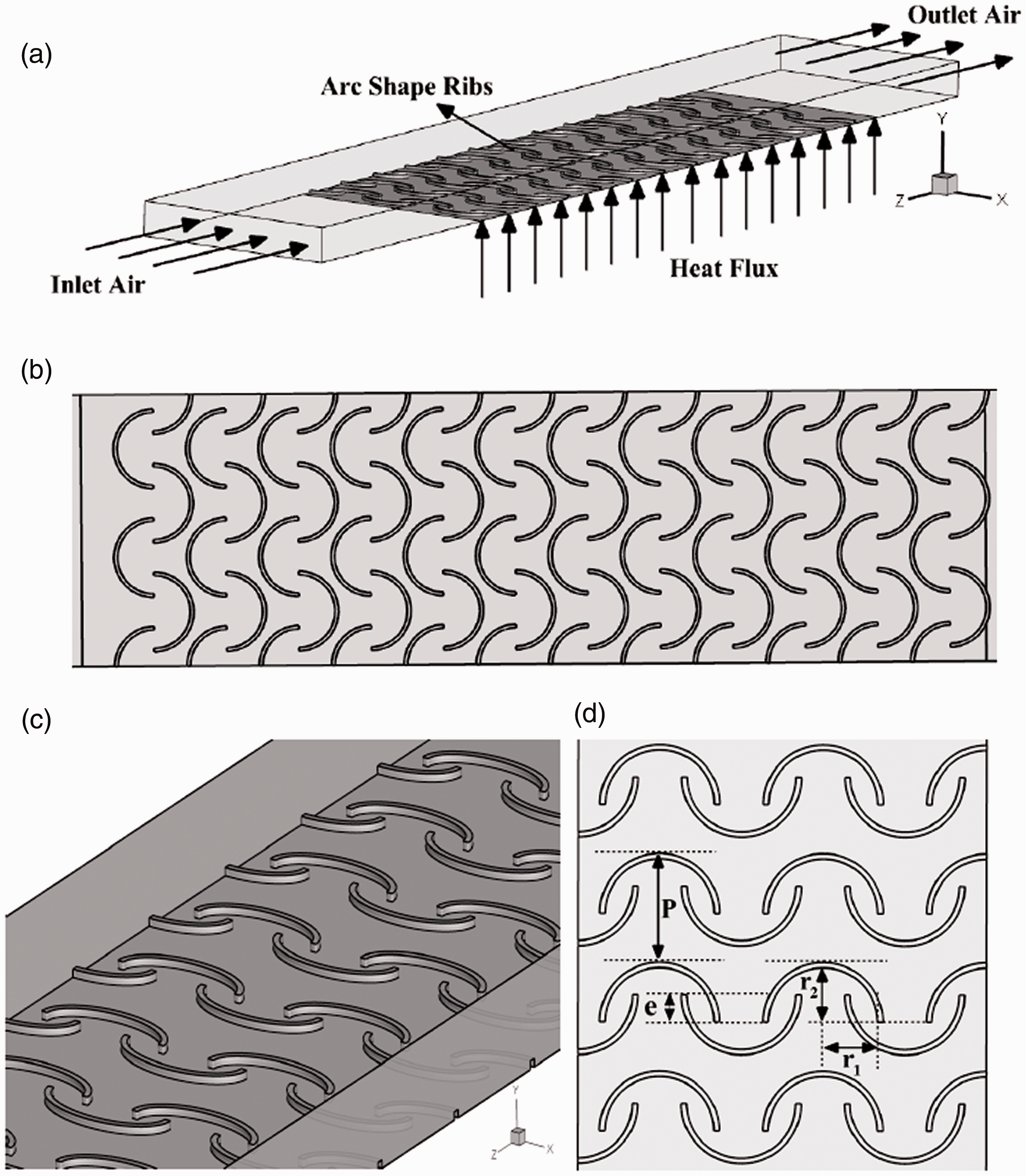
(a) Schematic view of the proposed SAH, (b) 2 D schematic of the placed innovative arc shaped ribs on the bottom surface of the considered SAH, (c) 3 D zoom on the ribs, and (d) main geometrical parameters of the arc shaped ribs.
Governing equations
Among the various turbulence models of the k–ε family, the RNG and realizable k–ε models are known to perform better when dealing with swirling flows.53–56 Also, according to the literature review, the realizable k-ε model exhibited better performance than the RNG one and so it will be used in the present study to close the momentum equations in the turbulent regime.
The natural way to treat wall boundaries is to make the grid sufficiently fine so that the sharp gradients prevailing there are resolved. In the present work, an enhanced wall treatment is used to model correctly the heat transfer process near the wall under constant heat flux. It consists of a near-wall modeling method, which combines a two-layer model (each layer having its own wall function) and a blending function to smooth the transition between these two layers.
The fluid flow and heat transfer are then governed by the following equations for a 3 D steady-state process:


Transport equations for the realizable k–ε model:

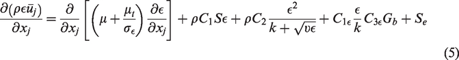


Equation (4) calculates the turbulence kinetic energy (k). Equation (5) calculates the dissipation rate of the turbulence kinetic energy (ε). Gb is the generation of turbulence kinetic energy owing to the buoyancy effect, Gk is the generation of turbulence kinetic energy because of the mean velocity gradients, μt is turbulent viscosity, Sk and Sɛ are user defined source terms. YM refers to the contribution of the fluctuating dilatation in compressible turbulence to the overall dissipation rate. C2 and C1ε are constant fixed to 1.9 and 1.44, respectively. σ
k
and σε are turbulent Prandtl numbers for k and ε, equal to 1 and 1.2, correspondingly.

The turbulent or eddy viscosity is computed from:


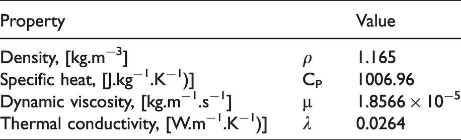
The turbulent heat flux is assumed to be negligible in the present case. It is noteworthy that the thermo-physical properties of air are kept constant throughout all the simulations. They are listed in Table 1.
Thermo-physical properties of air.
Numerical procedure and boundary conditions
The three-dimensional steady-state numerical simulations are performed using the commercial CFD code ANSYS Fluent 18.2 based on the finite volume method utilizing a commercial CFD code. The spatial discretization of the mass, momentum, turbulence kinetic energy, turbulence dissipation rate and energy equations has been achieved by a second-order upwind scheme. The velocity-pressure coupling has been overcame by the SIMPLE algorithm. To calculate the gradients, Green-Gauss cell-based method has been utilized. The convergence criteria were set to 10−6 for all residuals except for the energy equation (10−8).
Air enters the channel with constant temperature and velocity. Four Reynolds numbers based on the hydraulic diameter of the channel including 6000, 8000, 10,000, and 12000 are considered here. The inlet temperature of air is 300 K. The turbulence intensity is fixed to 5% at the inlet but has no noticeable influence on the results. A constant heat flux equal to 1000 W/m2 is imposed on the bottom surface of the SAH. It should be noted that to keep constant the surface area of the heater, the top wall of the ribs as well as the other part of the bottom surface without ribs are submitted to a heat flux, which is adjusted depending on the rib configuration to keep the overall heat flux received by the channel constant. Pressure is imposed at the outlet of the channel. No slip conditions are imposed on all walls.
Grid independence study
Four different structured grids composed of quadrilateral elements were considered. The average Nusselt number is illustrated in Figure 2 as a function of the Reynolds number. It corresponds to a SAH with ribs having a quadrangular cross section. The geometrical parameters are fixed to P = 50 mm, AR = 1, e = 0 mm and a = 2 mm.
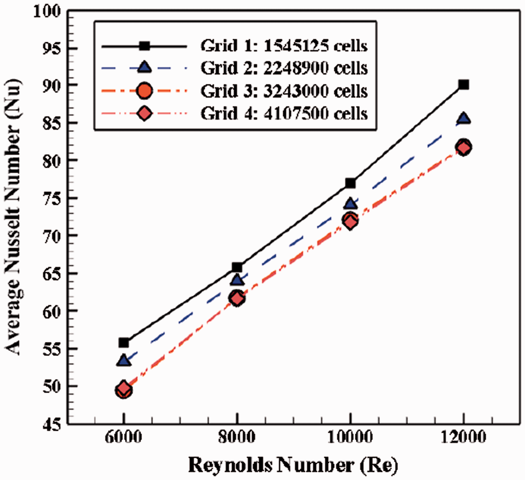
Independence grid study based on the average Nusselt number (Nu) variation with various inlet Reynolds numbers.
Grids 3 and 4 provide undistinguishable results such that grid 3 with 3,243,000 cells will be used in the following sections to save computational efforts. To calculate accurately the heat transfer near the bottom wall and ribs under a constant heat flux, the grid was refined using 10 prismatic layers in these regions with a refinement ratio equal to 1.1. It leads to a maximum value of the wall coordinate y+ within the channel equal to 0.82, which is well suited when using enhanced wall treatment to correctly model the viscous sublayer (y+<1).
Validation of the solver
There are so many correlations to predict turbulence heat transfer coefficient inside an empty duct and for given ranges of Nusselt and Prandtl numbers. The Dittus-Boelter correlation predicts the mean Nusselt number as a function of the Reynolds number for fully developed flows in an empty duct. Figure 3(a) indicates the present results follow the Dittus-Boelter correlation with a maximum difference of 7.6%. For a constant wall temperature, the correlation of Seban and Shimazaki is also chosen to further validate the present numerical results. This correlation was recommended for Pe.D ≥ 100. As shown in Figure 3(b), the agreement between the present results and the Seban and Shimazaki’s correlation is fairly good with a maximum difference of 9.2%.
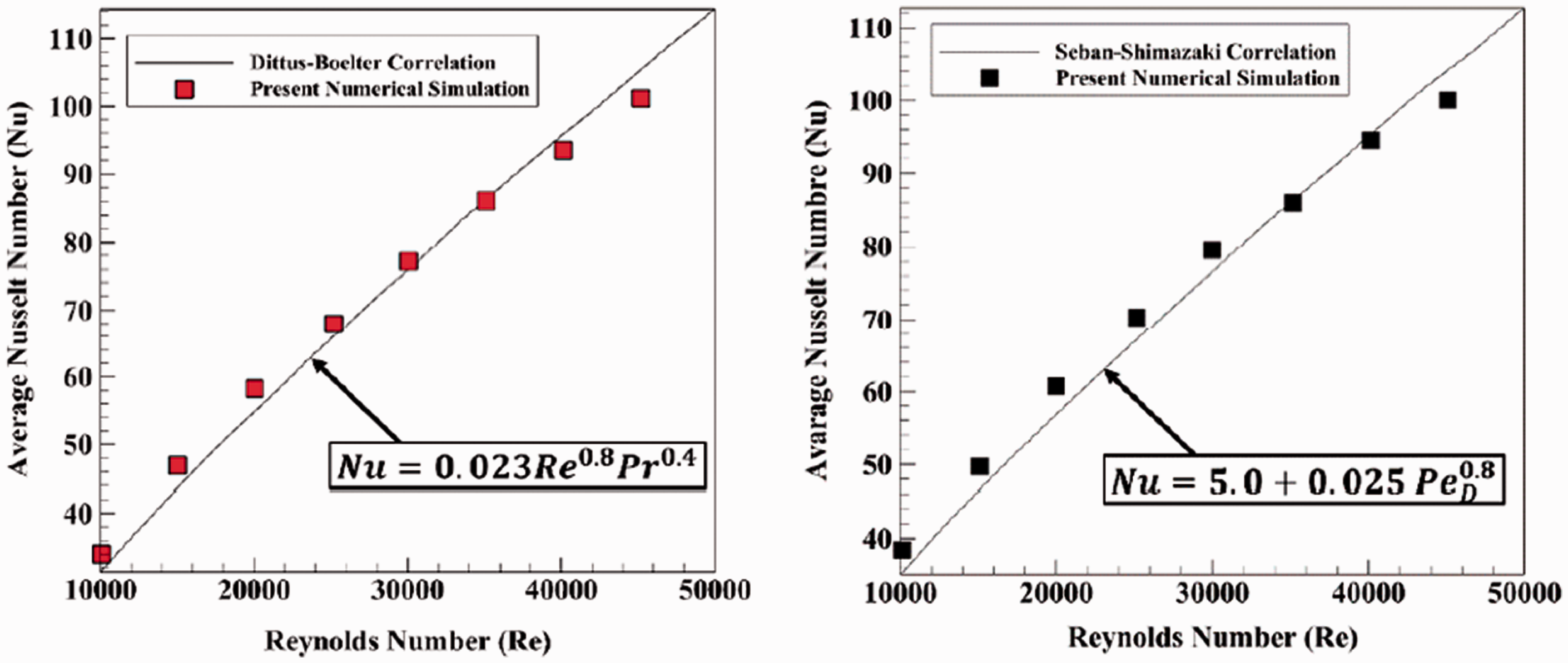
Comparisons in terms of the theoretical Nusselt number with the present simulations; (a) Comparisons with (a) the Dittus-Boelter correlation and (b) the Seban-Shimazaki correlation.
In order to verify the numerical method for modeling the heat transfer in the proposed solar air heater, the present CFD results are compared to the experimental data of Thakur et al.
57
for a square duct equipped with hyperbolic ribs. The absorber plate area is kept constant and fixed to 100 × 100 mm2. The hyperbolic ribs are characterized by e = 1 mm and P = 10 mm. The comparison is displayed in Figure 4 in terms of the averaged Nusselt number variation with the inlet Reynolds number. The Reynolds Re and Nusselt Nu numbers are defined as:


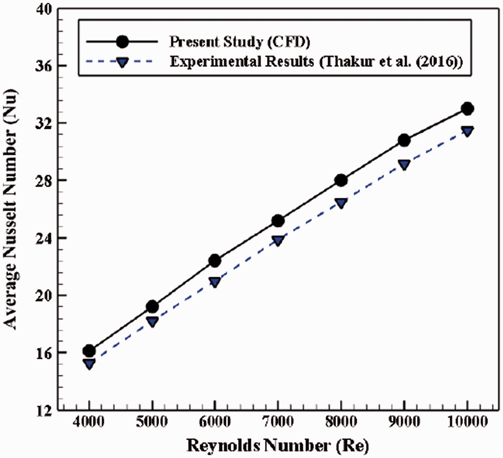
Comparison of the obtained numerical results from the present study with the experiments of Thakur et al. 57
The achieved outcomes by the present numerical work show pretty decent agreement with the experiments of Thakur et al. 57 with an average deviation of 4.28%. The discrepancies besides do not vary too much with the Reynolds number.
Results and discussion
The influence of adding innovative arc shaped ribs in the SAH bottom surface on the heat transfer enhancement is numerically investigated. The influences of the type of the rib cross section, the distance between the ribs (e), the aspect ratio and the pitch of the ribs (P) on the thermal performance of SAH are quantified in the following subsections. The results are discussed in terms of the average Nusselt number (Nu), pressure drop (ΔP), friction factor (f) and coefficient of performance (COP).
The friction factor is given by:
These two parameters can be combined to form a kind of coefficient of performance (COP) in the following way:
Influence of the shape of the rib cross section
Three different types of the rib cross section including quadrangular, triangular and circular shapes are considered here. In this section, the influence of the shape of the rib cross section for different rib heights is quantified in detail by keeping all the other parameters constant (AR = 1, P = 40 mm, e = 5 mm). The schematics of the investigated models are illustrated in Figure 5. The rib height is varied between 1.5 and 3 mm. The average temperature of the wall and the average Nusselt (Nu) number are displayed in Figure 6(a) and (b), correspondingly, as a function of the rib height for the three types of cross section. The results are compared to the base case without rib.
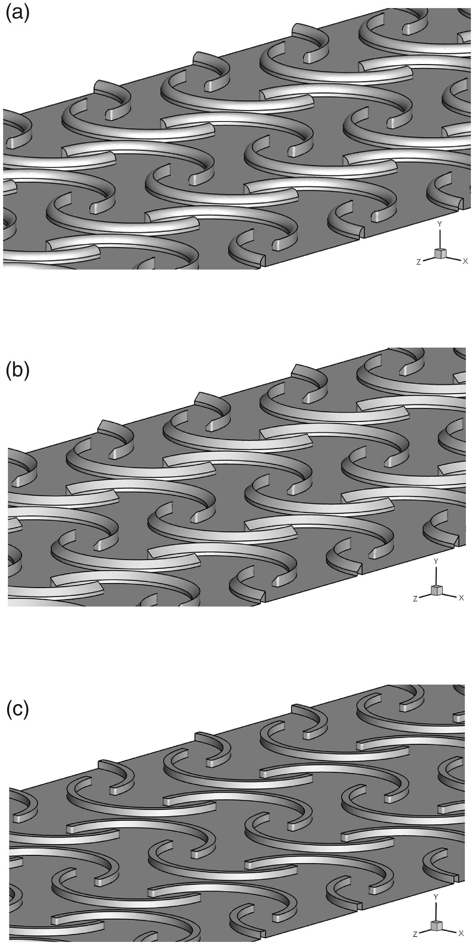
3 D views of the considered ribs with three different cross sections. (a) Circular Cross Section, (b) Triangular Cross Section, and (c) Quadrangular Cross Section.
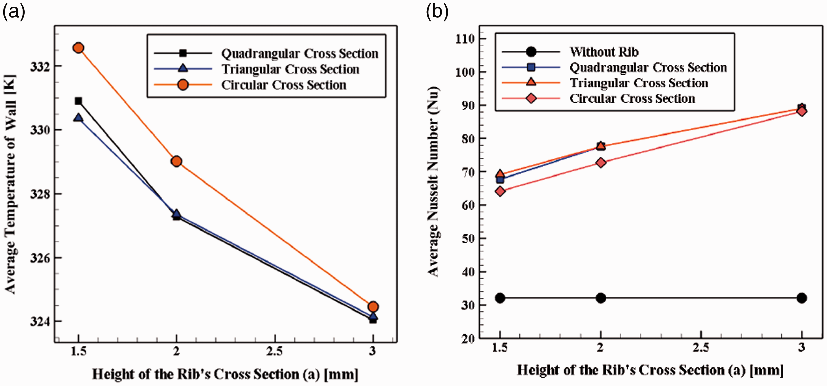
(a) The average temperature of the wall and (b) the average Nusselt number (Nu) versus different heights of the rib cross section for various shapes of the rib cross section and Re = 10,000.
According to Figure 6(a), whatever the rib height, the circular type exhibits a higher wall temperature whereas quadrangular and triangular types lead to the lowest ones with only small differences. At the same time, the circular shape has the lowest heat transfer rate. Figure 6(b) shows that ribs whatever their shape provide much higher average Nusselt numbers compared to the base case without ribs. Quadrangular and triangular types have a greater heat transfer in comparison with the circular type. Also increasing the rib height leads to higher Nusselt number for all considered shapes.
The pressure drop is displayed in Figure 7 as a function of the rib height and for the three types of cross section. Consequently, the results are obtained at a constant Reynolds number (Re = 10,000), so based on equation (15), the friction factor can be directly linked to the pressure drop. As expected, these two quantities increase by increasing the rib height in all cases. The highest and lowest pressure drops (or friction factor) are obtained for the triangular and circular types, respectively.
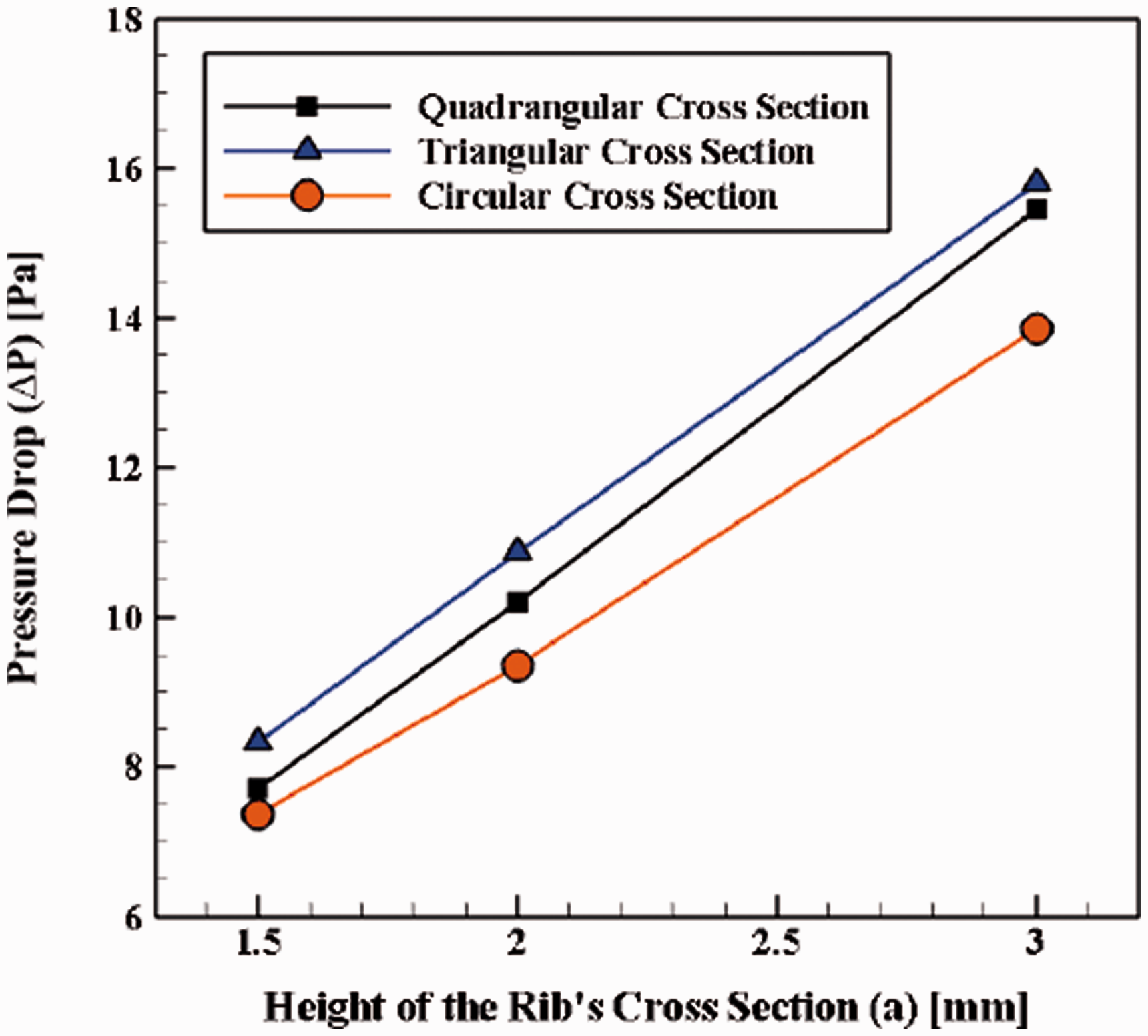
Variations of the pressure drop (ΔP) as a function of the rib height for various kinds of cross-sections at Re = 10,000.
The ratio of average Nusselt numbers (Nu/Nu0) and the ratio of friction factors (f/f0) are shown in Figure 8(a) and (b), correspondingly, as a function of the rib height (denoted a) and for the four configurations. It is worth mentioning that index 0 refers to the SAH without ribs. Figure 8(a) shows that adding ribs whatever their shape and height enhances the average Nusselt number in comparison with the simple SAH. More precisely, this enhancement is higher for the triangular shape whatever the rib height. The maximum and minimum improvements in average Nusselt number are obtained for the triangular and quadrangular cross-sections with a = 3 mm and a = 1.5 mm, respectively.
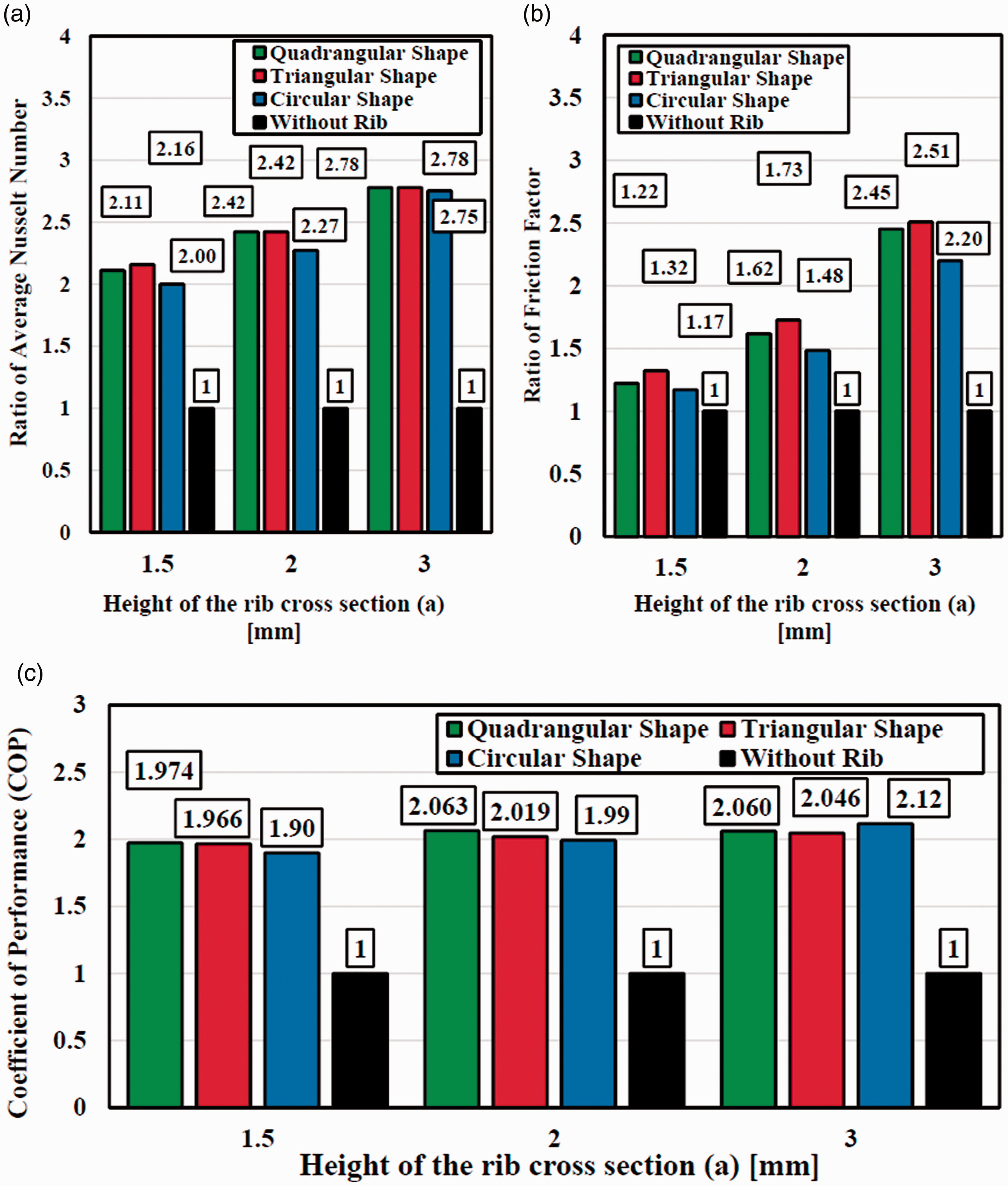
(a) Ratio of Nusselt numbers (Nu/Nu0), (b) ratio of friction factors (f/f0) and (c) the coefficient of performance (COP) versus three different rib heights and for different rib shapes at Re = 10,000.
Figure 8(b) shows that the ratio of friction factors for ribs with any kinds of cross section is higher than for the simple SAH. Also, the maximum and minimum improvements in terms of the friction factor ratio in comparison with the simple SAH are obtained for the triangular (a = 3 mm) and quadrangular (a = 1.5 mm) cases, respectively. Finally, the variations of the coefficient of performance (COP) are illustrated in Figure 8(c). COP is a main parameter to analysis the thermal performance of any heat transfer system as it combines both the heat transfer enhancement and the pressure drop (related to the required pumping power). Whatever the rib shape, COP increases by increasing the rib height and reaches a maximum for a = 3 mm. The highest and lowest COP improvements are obtained for the circular shaped rib with a = 3 mm and the triangular shaped one with a = 1.5 mm, reaching 112% and 96.6% enhancements, respectively.
To well recognize the influence of the rib shape, the corresponding velocity vectors are presented in Figure 9. The ribs persuade swirl flows with a recirculation in the rib wake, which enhances the heat transfer between the heater (bottom wall) and the fluid. It is noticeable that the recirculation behind the circular rib is smaller compared to the other cases provoking a lower pressure drop. However, it is very important to mention that the use of ribs with any geometry has a significant impact on the thermal performance of SAH because of the produced secondary flows behind the ribs (see Figure 9).
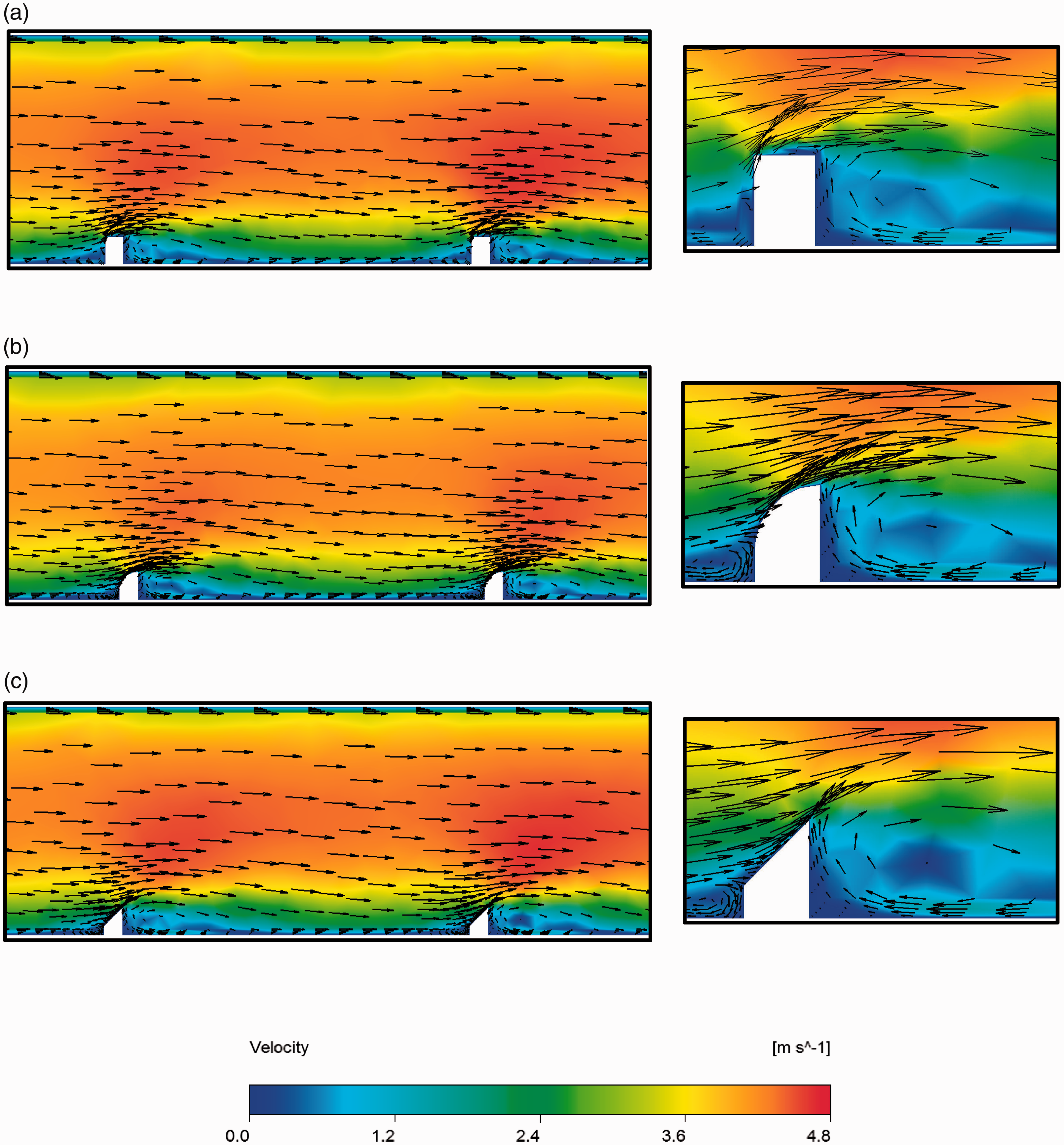
Velocity vectors for different types of ribs at Re = 10000 and a = 3 mm: (a) quadrangular, (b) circular, and (c) triangular shape cross section.
Influence of the distance between two ribs (e)
In this section, the effect of the distance between the ribs (e) on the thermal efficiency of the present SAH is studied numerically. Three various distances between the ribs including e = 0, 5, and 10 mm are selected. The simulations are done for four Reynolds numbers ranging between 6000 and 12000. The aspect ratio of the ribs (AR), the pitch of the ribs (P), and height of the ribs (a) are kept constant as 1, 40 mm, and 2 mm, respectively. The schematics of the considered models with different distances between the ribs are shown in Figure 10.
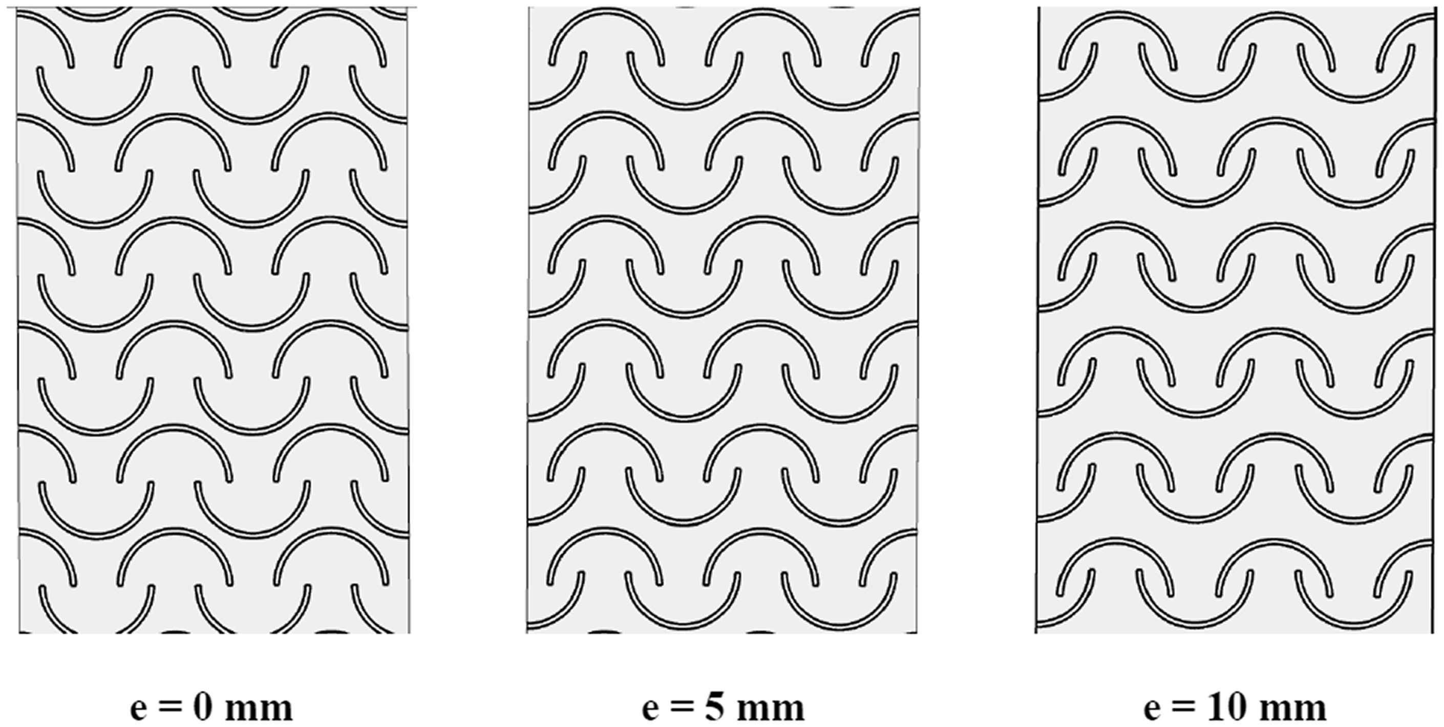
Schematics of the considered models for different distances between the ribs (e).
The pressure drop (ΔP) and average Nusselt number (Nu) variation with various Reynolds numbers for different aspect ratios of the ribs are shown in Figure 11(a) and (b), respectively. The differences in terms of ΔP between the considered models remain very low (Figure 11(a)). However, whatever the Reynolds number, the highest pressure drop is obtained for e = 5 mm while its minimum appears for e = 0 mm. According to Figure 11(b), the highest average Nusselt number belongs to the case with e = 5 mm but its minimum value varies with the inter-rib distance, namely e = 0 mm at Re = 6000 and e = 10 mm at Re = 12,000. As expected, as the Reynolds number rises, the average Nusselt number augments too due to the forced convection and the trend is the same for all values of the distance between the ribs (e).
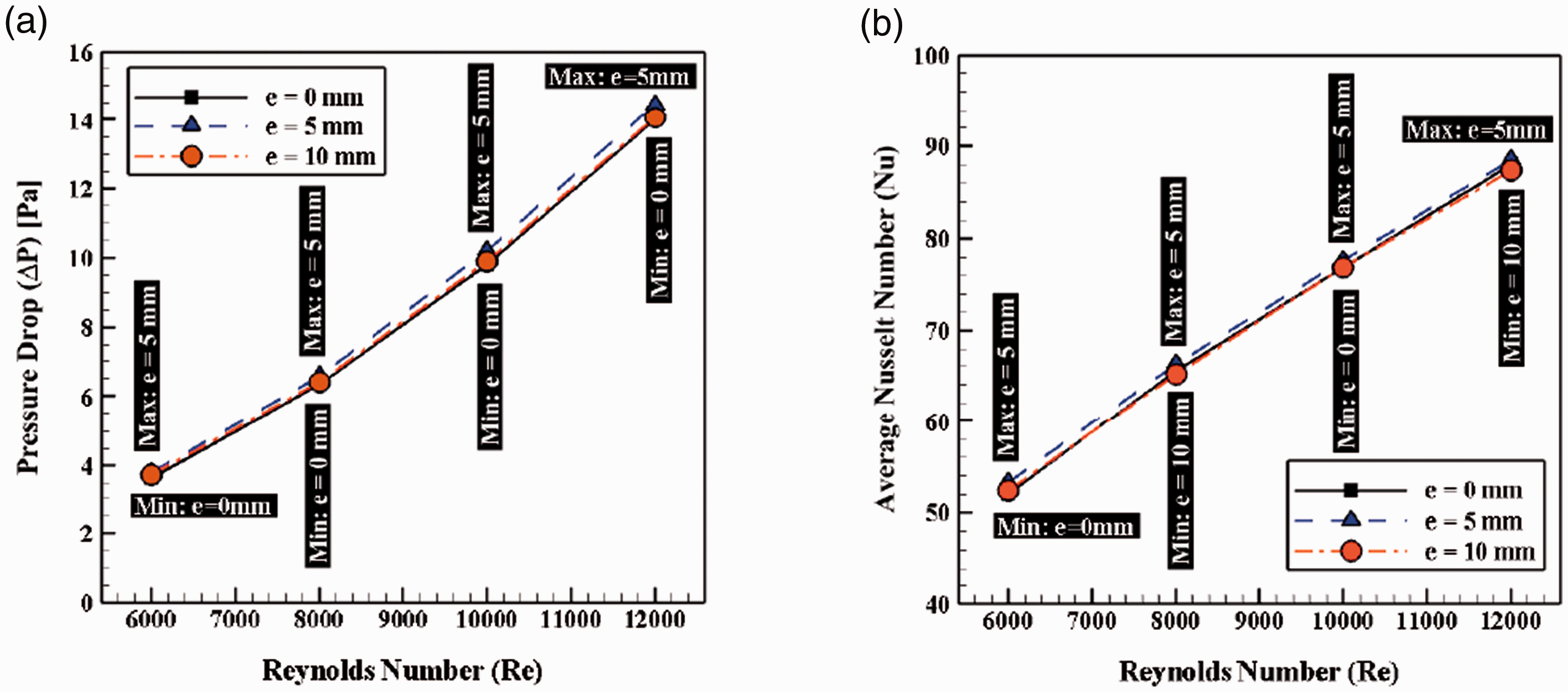
Influence of the Reynolds number on (a) pressure drop and (b) average Nusselt number (Nu) for three distances between the ribs (e).
To better understand the influence of the distance between the ribs (e) on the heat transfer amount, temperature contours are displayed in Figure 12 at the bottom surface of the SAH for Re = 12,000, AR = 1, P = 40 mm, and a = 2 mm. The case with e = 5 mm exhibits the lowest area of hot spots behind the ribs, which means that more heat transfer happens from the bottom surface to the fluid. It should be noted that the differences between the considered models remain very small. However, among the evaluated models, the case with e = 5 mm exhibits the better thermal performance.
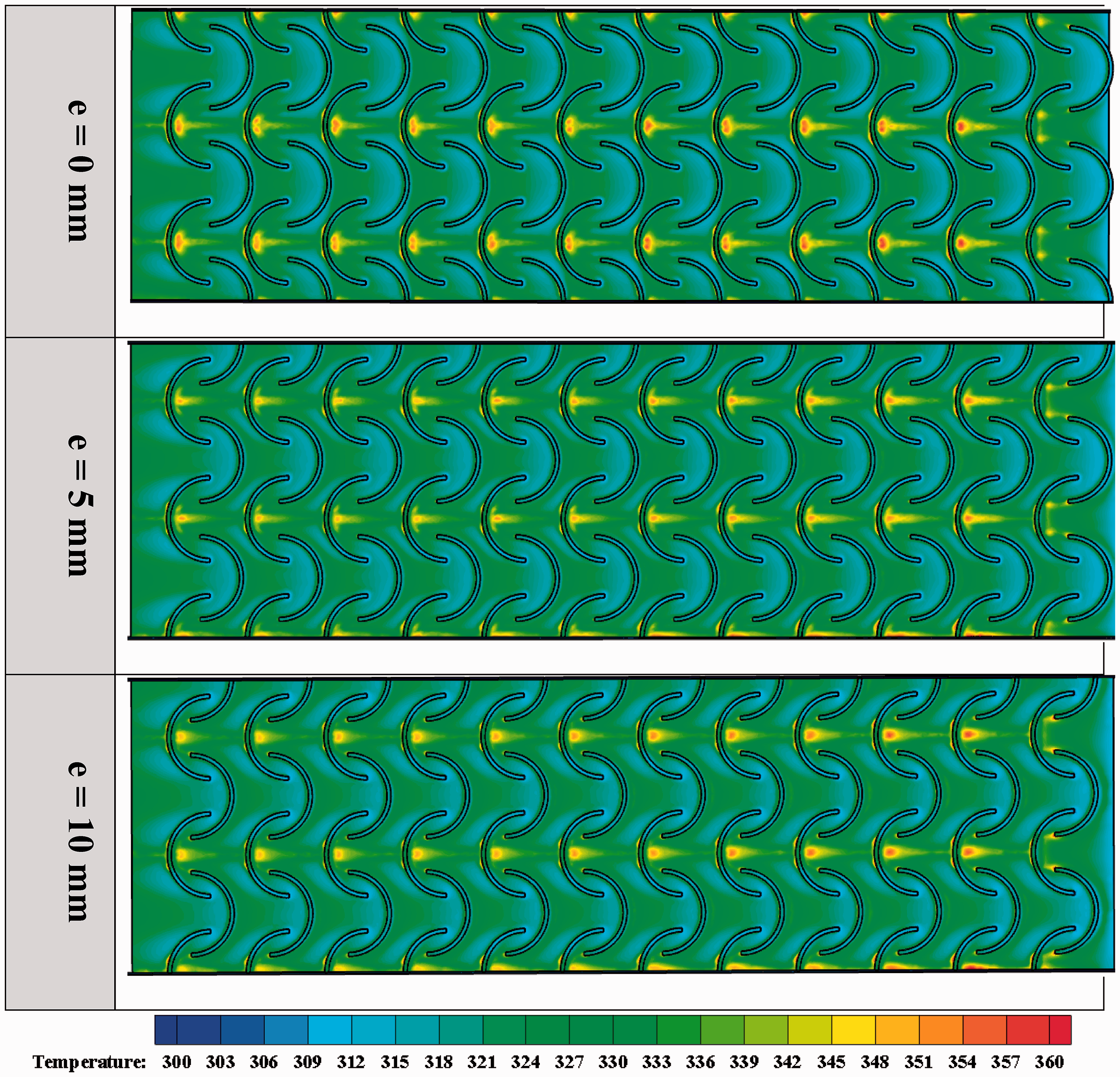
Temperature contours for three distances between the ribs (e) at Re = 12000 and Y = 0.
The ratios of the average Nusselt number (Nu/Nu0) and the friction factor (f/f0), and the COP (equation (16)) are depicted in Figure 13(a) to (c), respectively, as a function of the Reynolds number for three distances between the ribs (e). Figure 13(a) illustrates that for considered Reynolds numbers, the case with e = 5 mm exhibits a higher ratio of average Nusselt number. However, the difference between cases with e = 0 and 10 mm are very small. Also, based on Figure 13(b), the case with e = 5 mm has a higher ratio of friction factor than the other cases. Figure 13(c) depicts that at low Reynolds number (Re = 6000), the case with e = 5 mm provides the highest COP by a 121% improvement in comparison with the case without ribs (COP = 1). It has to be compared to cases with e = 0 mm and e = 10 mm, which lead to a 119.2% and 118.8% improvement, respectively.
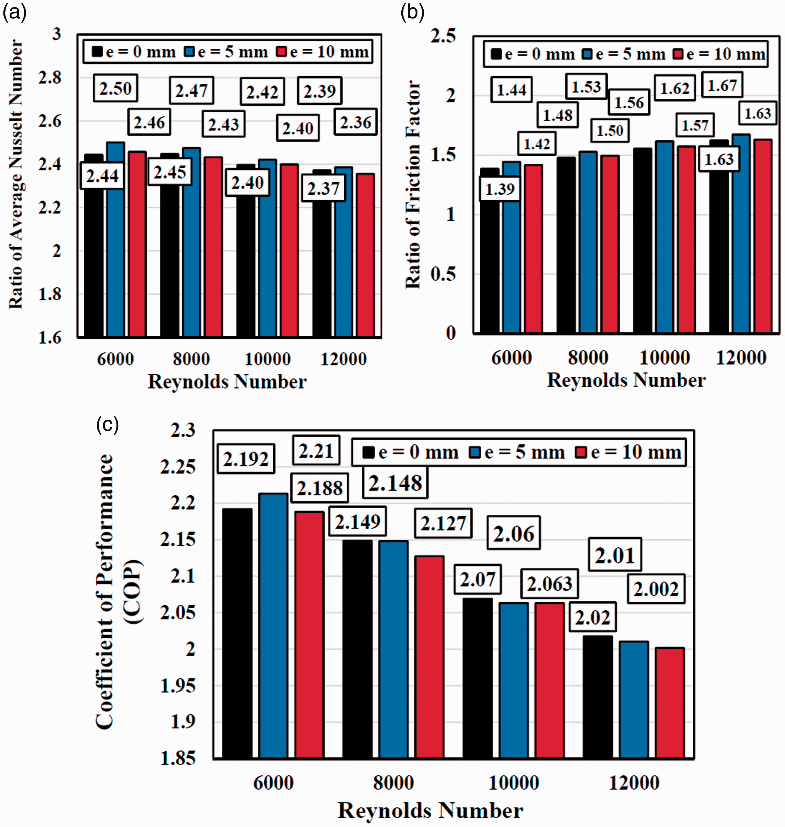
Influence of the Reynolds number on (a) the average Nusselt number ratio (Nu/Nu0), (b) the ratio of friction factor (f/f0), and (c) coefficient of performance (COP) for different distances between the ribs (e) and Reynolds numbers.
Figure 14 shows the contours of the velocity magnitude for different distances between the ribs (e) at Re = 12,000. Its influence remains weak for this range of e values. Nevertheless, one can notice that the blue regions representing the secondary flows behind the ribs for e = 5 mm are larger (even of the differences with the other cases are small) leading to higher pressure drop and also heat transfer rate. It can be concluded that in the case with e = 5 mm, the proposed geometry of the arc-shaped ribs causes more secondary flows behind the ribs and consequently more heat exchange rate.
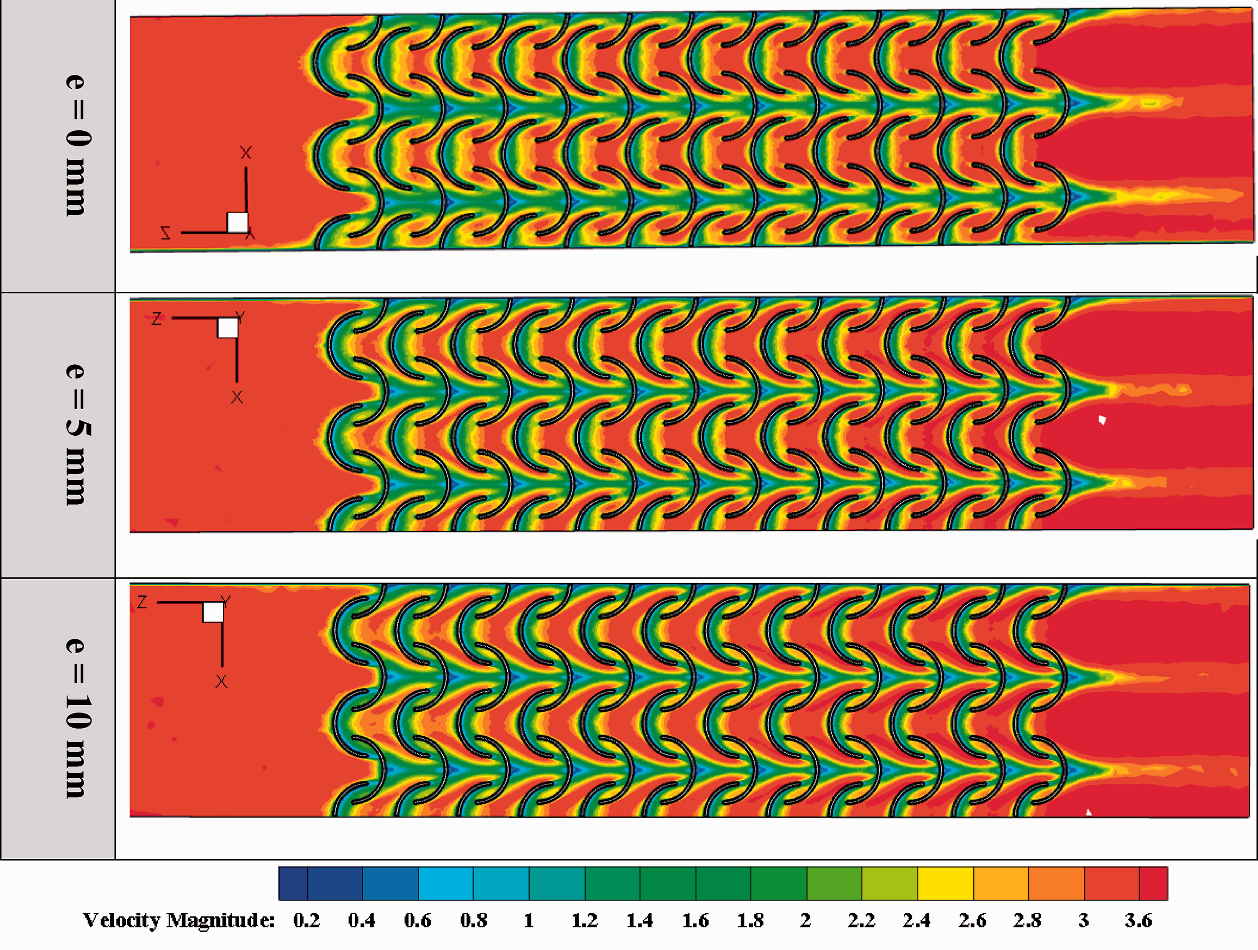
Contours of the velocity magnitude for different distances between the ribs (e) at Re = 12000 and Y = 1.5 mm.
Influence of the rib pitch (P)
In this section, the effect of the pitch (P) of the ribs on the thermal performance of the SAH is investigated numerically. Three different pitch values, namely P = 40, 50, and 60 mm are selected. The distance between the ribs (e), the aspect ratio (AR) and the rib height (a) are kept constant as 0 mm, 1 and 2 mm, correspondingly. The schematics of the considered models with different aspect ratios are displayed in Figure 15.
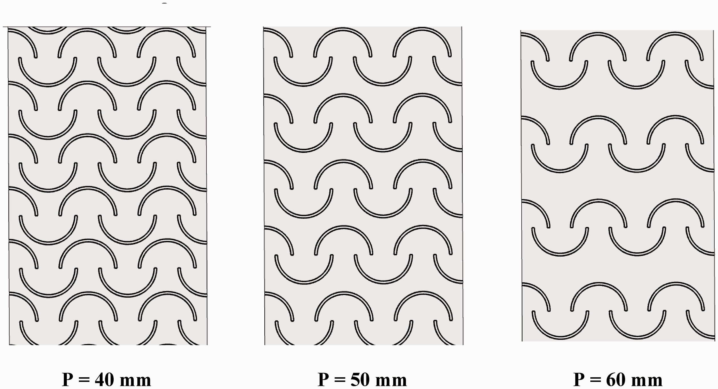
Schematics of the considered models with different pitch values of the ribs (P).
The average Nusselt number (Nu) and pressure drop (ΔP) are displayed in Figure 16(a) and (b), respectively, variation with the Reynolds number for different aspect ratios of the ribs. According to Figure 16(a), the highest average Nusselt number is obtained for P = 40 mm and the minimum one for P = 60 mm. Also, growth in Reynolds number causes an augmentation in average Nusselt number because of the forced convection and the trend is the same for all models with different pitches.
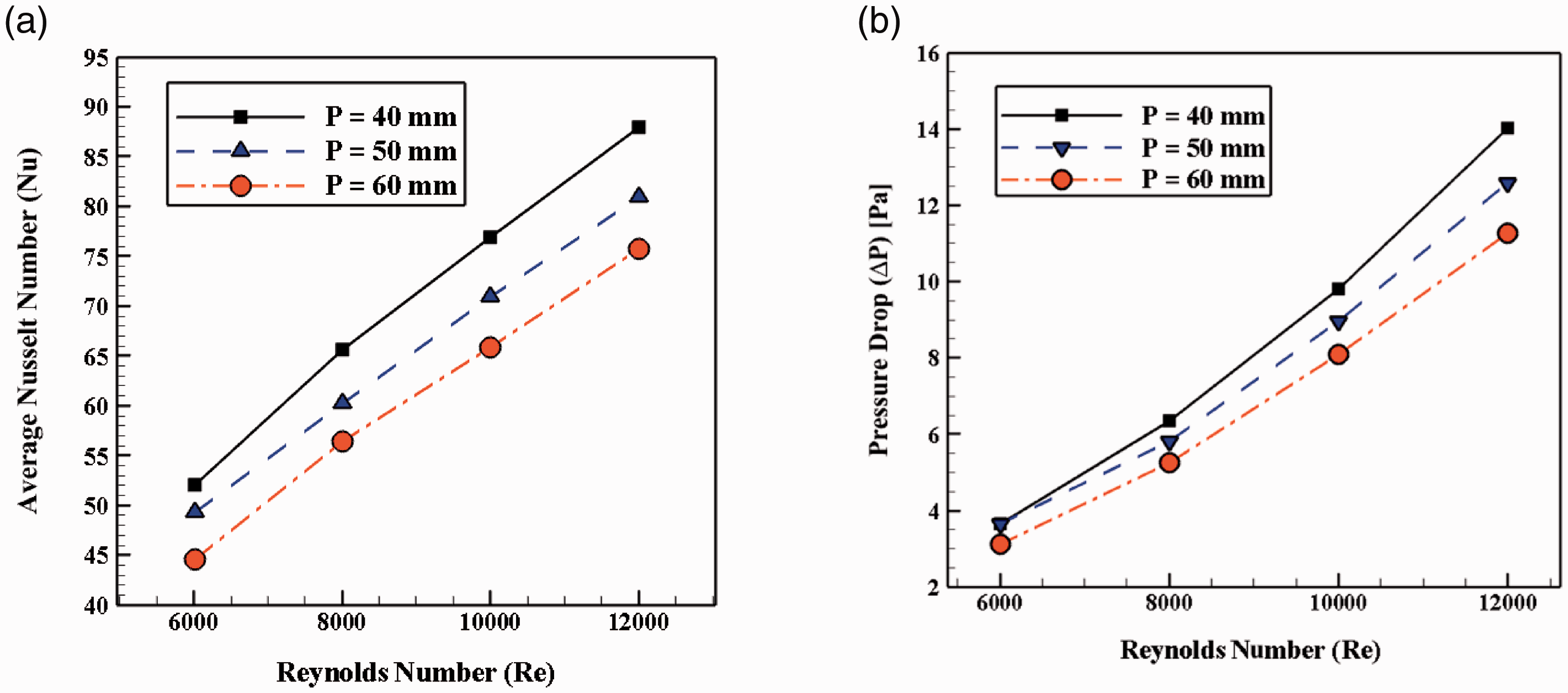
Influence of the Reynolds number on (a) the Nusselt number along the bottom wall with a constant heat flux and (b) pressure drop for various pitch values of the ribs (P).
Figure 16(b) shows that at low Reynolds number (Re = 6000), there is no noticeable difference when varying P. As the Reynolds number increases, the difference gets higher. Whatever the Reynolds number, the maximum pressure drop is obtained for P = 40mm and it decreases by increasing the pitch. To better highlight the heat transfer amount and the influence of the rib pitch, temperature contours at the bottom wall of the SAH are illustrated in Figure 17 for the corresponding cases.
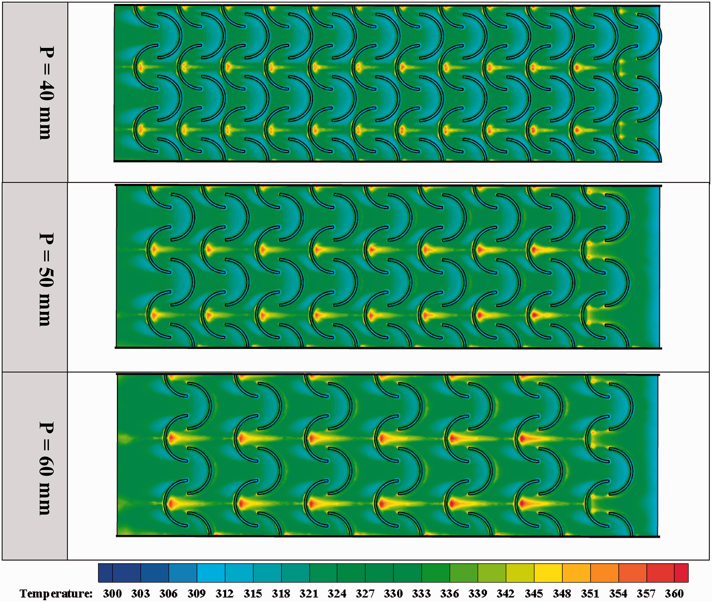
Temperature contours for three pitch values of the ribs (P) for Re = 12,000.
Figure 17 depicts that hot spots appear behind the first row of arc shaped ribs. The surface covered by the hot spots is a good indicator of the heat transfer performance of the SAH. Small hot spot areas are related to higher heat transfer from the bottom wall to the fluid (air). For P = 40 mm, the hot spots behind the arc shaped ribs are smaller compared to the other cases, which means that it can be considered as the best configuration. The size of the hot spots (resp. the heat transfer) increases (resp. decreases) with the pitch.
The ratios of the average Nusselt number (Nu/Nu0) and of the friction factor (f/f0) and the resulting COP (see equation (16)) are displayed in Figure 18(a) to (c), respectively, as a function of the Reynolds number (Re) and for various pitch values (P).
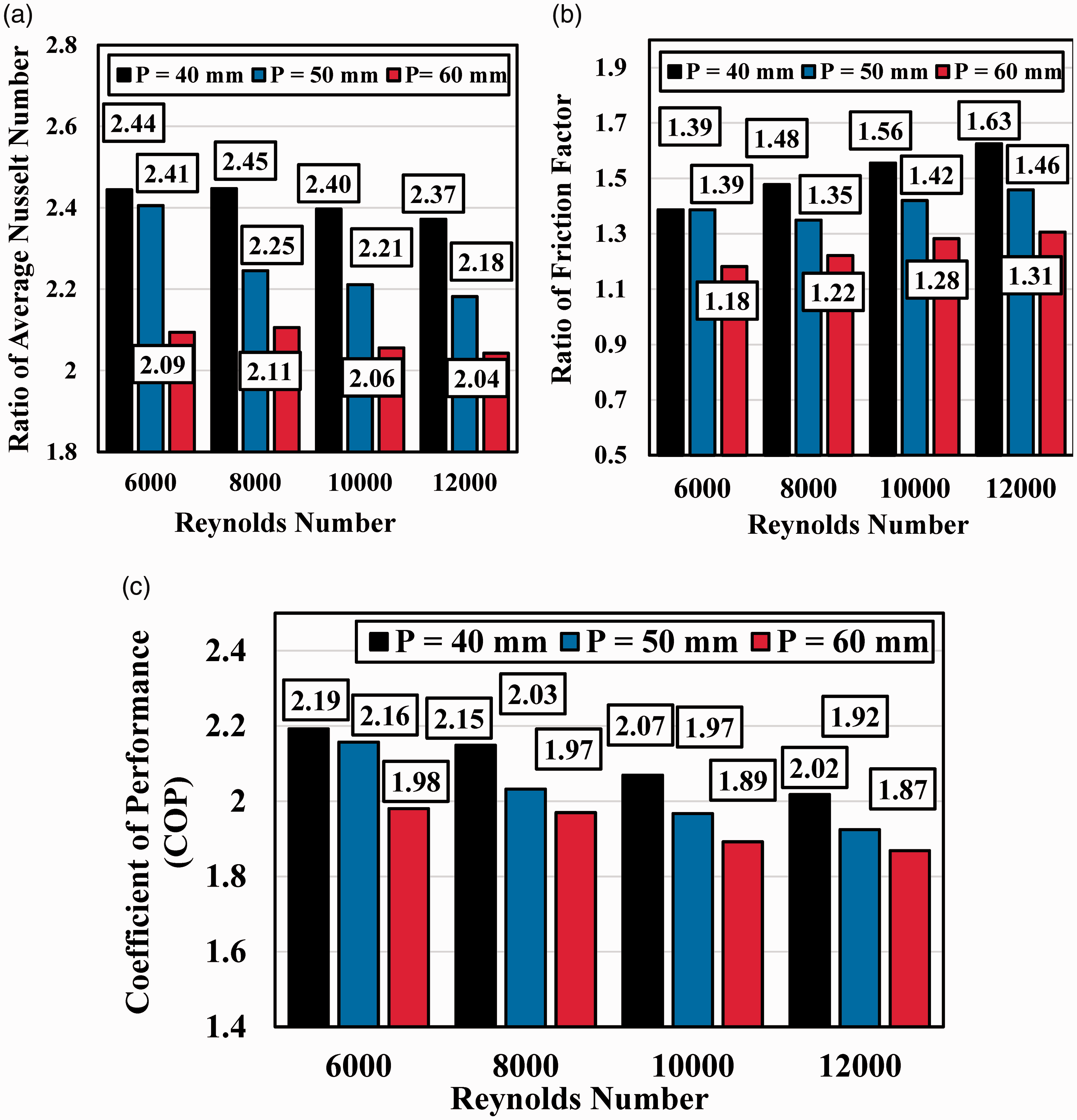
Influence of the Reynolds number on the (a) ratio of average Nusselt number (Nu/Nu0), (b) ratio of friction factor (f/f0), and (c) coefficient of performance (COP) for three pitch values.
Figure 18(a) shows that for all Reynolds numbers, the highest and lowest ratios of the averaged Nusselt number (Nu/Nu0) are obtained for the cases with P = 40 mm and P = 60 mm, respectively. Also, the case with P = 40 mm and Re = 8000 depicts the highest ratio of average Nusselt number by a 145% improvement in comparison with the simple SAH without ribs. Moreover, the case with P = 60 mm and Re = 12000 presents the lowest ratio of average Nusselt number by a 104% enhancement compared with the plain SAH.
According to Figure 18(b), all the investigated cases present higher friction factors compared to the plain SAH. On the other hand, the ratio of friction factor (f/f0) is greater than one for all models. Also, it can be concluded that the highest and lowest ratios of friction factor (f/f0) belong to cases P = 40 mm (at Re = 12000) and P = 60 mm (at Re = 6000) by 63 and 18% improvements (compared to plain SAH), respectively.
So, the best parameter to analyze the thermal performance of the SAH by considering both ratios of average Nusselt number and friction factor appears to be the coefficient of performance (COP) (Figure 18(c)). Accordingly, all the proposed models depict COP values higher than one so thermal performance of all models is greater than for the plain SAH. From Figure 18(c), the maximum COP belongs to the model with P = 40 mm at Re = 6000 by a 119% enhancement compared to the plain SAH. Furthermore, the model with P = 60 mm at Re = 12000 has the lowest COP by an 87% improvement in comparison with the case without ribs.
Figure 19 presents the contours of the velocity magnitude for three pitch values in the plane Y = 1.5 mm and for Re = 12,000. For the lowest pitch P = 40 mm, the spatial extension of the red region characterized by a higher velocity magnitude is small. The fluid flow has then a lower velocity, which causes a higher heat transfer rate. On the other hand, for case P = 60 mm, the red region extends between the ribs, meaning a higher velocity. The time for heat transfer between the heater and the fluid is then reduced and as a consequence, the heat transfer rate decreases.
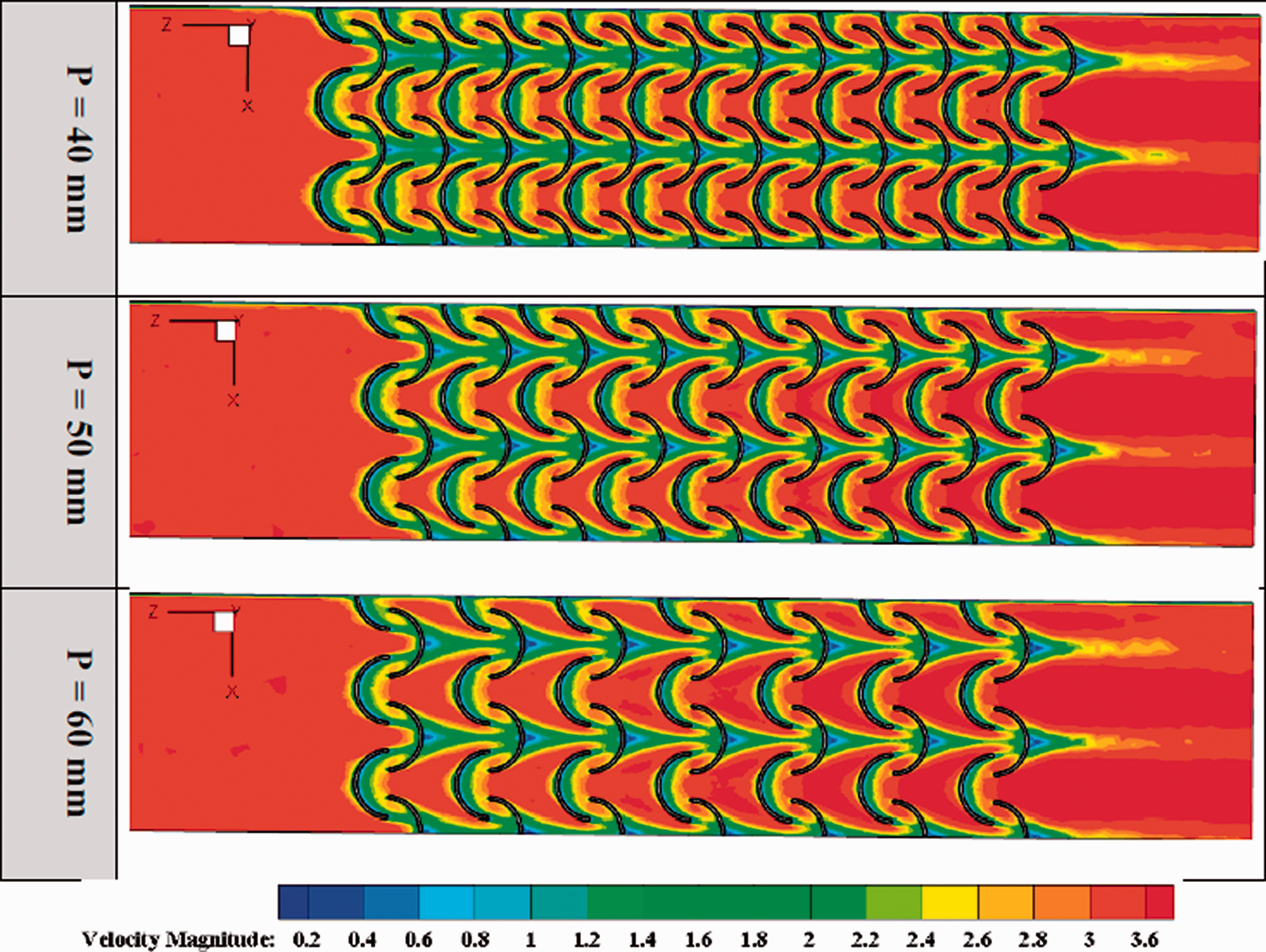
Contours of the velocity magnitude in the plane Y = 1.5 mm for three pitch values at Re = 12,000.
The velocity vectors for various pitches of the ribs are illustrated in Figure 20 for Re = 12000. At low pitch (here P = 40 mm), the distance between the ribs is small, inducing weaker velocity in the gap between two ribs. So the time for heat transfer between the heater (bottom wall of the solar air heater) and air is sufficient, leading to a high heat transfer rate. On the contrary, as the pitch of the ribs increases from P = 40 to P = 60 mm, the high velocity region between the ribs extends and the velocity magnitude increases. Time is then not sufficient for a good heat transfer between the air and heater, and so the heat transfer rate decreases, which confirms the above results (Figures 16 to 19).
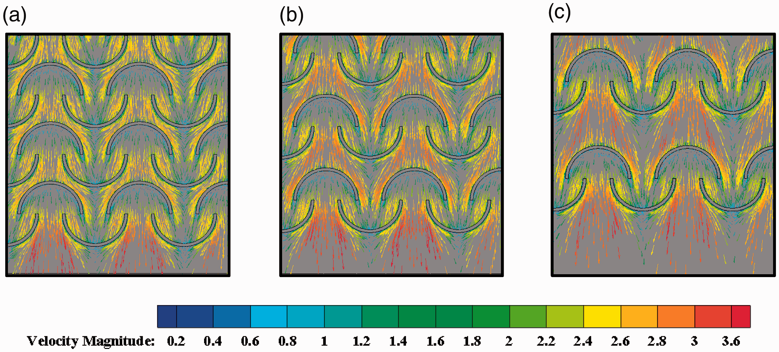
Velocity vectors for different rib pitches: (a) P = 40 mm, (b) P = 50 mm and (c) P = 60 mm. Results obtained for Re = 12000 and Y = 1.5 mm.
Influence of the rib aspect ratio (AR = r1/r2)
In this section, the effect of the aspect ratio of the ribs on the thermal performance of the SAH is investigated numerically for three aspect ratios including 2, 1, and 0.5 and Reynolds numbers between 6000 and 12000. The distance between the ribs (e), the pitch of the ribs (P) and their height (a) are kept constant as 0, 40 mm and 2 mm, correspondingly. The schematics of the considered models with different aspect ratios are shown in Figure 21.
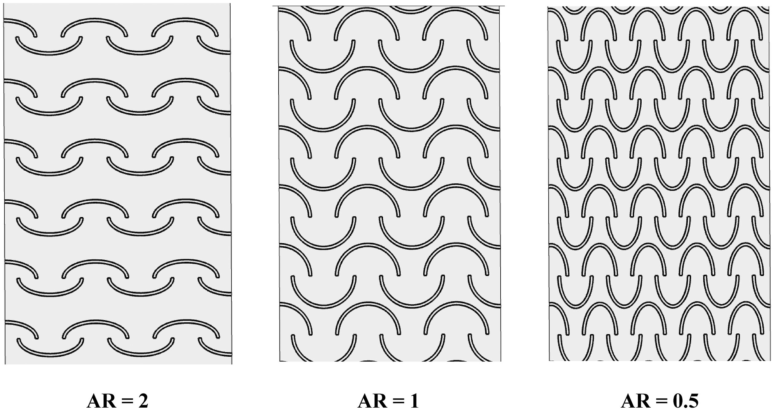
Schematics of the models with different aspect ratios.
The average Nusselt number (Nu) and pressure drop (ΔP) are illustrated versus the Reynolds number for different aspect ratios (AR) in Figure 22(a) and (b), respectively. Figure 22(a) presents that the maximum average Nusselt number belongs to the case with aspect ratio equal to 1 (AR = 1), while its lowest value is found for AR = 2. As expected, growth in Reynolds number causes the augmentation in average Nusselt number owing to the forced convection. Figure 22(b) shows that the lowest pressure drop appears for AR = 0.5, while there is noticeable difference between the cases AR = 1 and AR = 2.
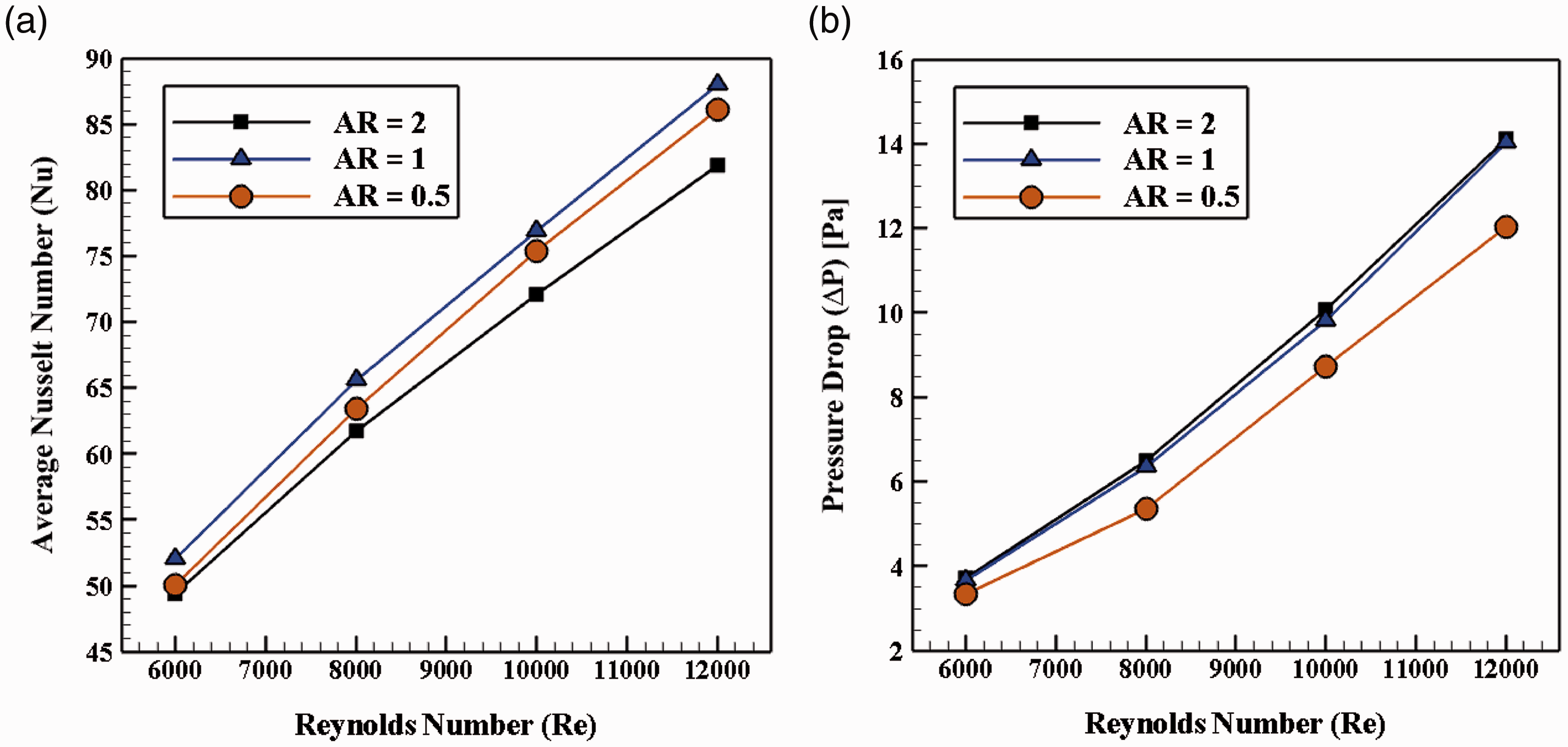
Variations of (a) the average Nusselt number along the bottom wall with constant heat flux and (b) average Nusselt number (Nu) with the Reynolds number for three aspect ratios AR.
To better realize the effect of the aspect ratio (AR) on the heat transfer process, the corresponding temperature contours are shown in Figure 23 for different aspect ratios at Re = 12,000. For AR = 0.5, regions with lower temperatures are wider compared to the other aspect ratio values, which confirms that a higher heat transfer rate is obtained for that configuration.
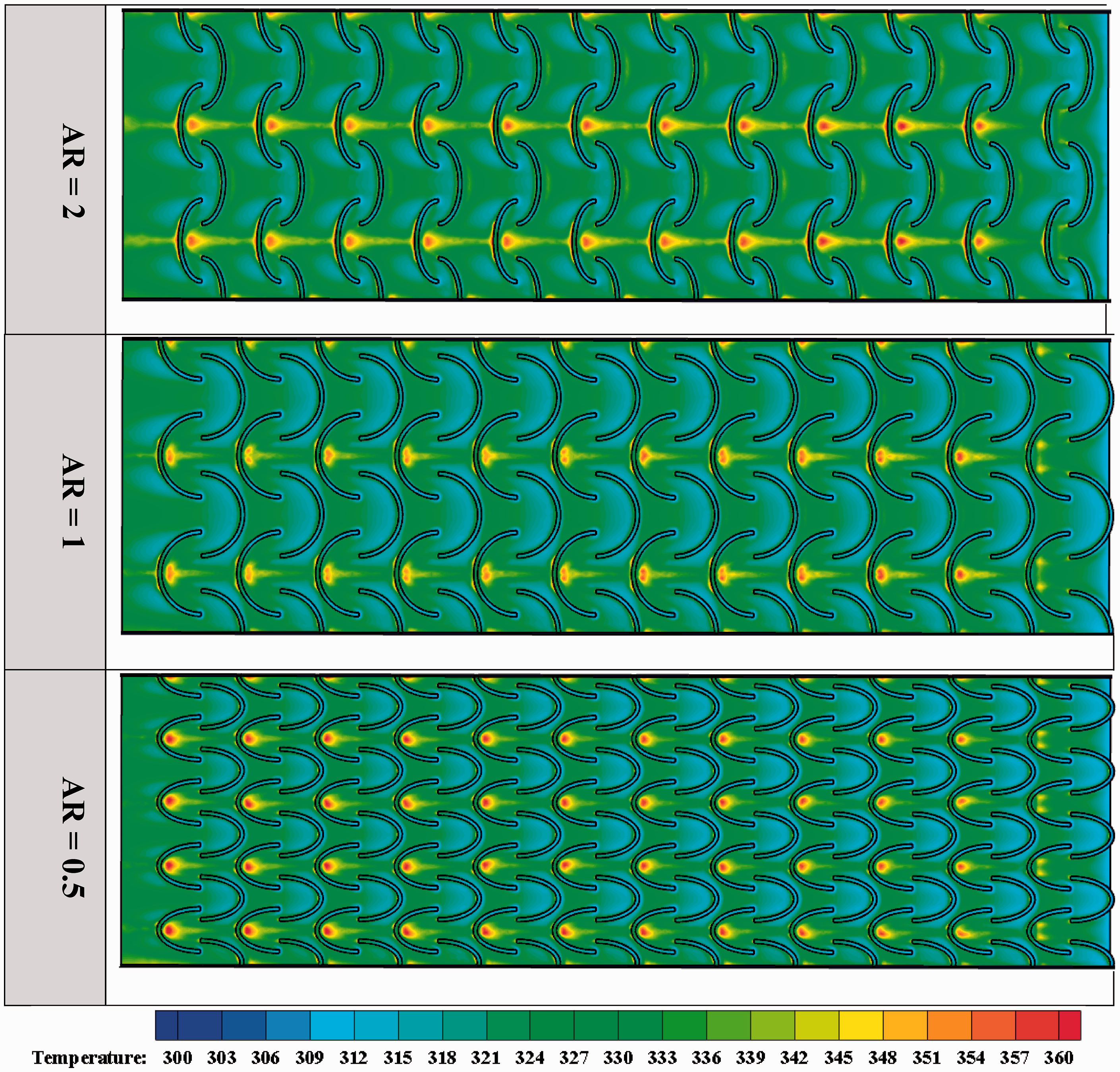
Temperature contours for different aspect ratios (AR) at Re = 12000 and Y = 0 mm.
The ratios of average Nusselt number (Nu/Nu0) and of friction factor (f/f0) are depicted in Figure 24(a) and (b), respectively. It should be noted that index 0 refers to the simple solar air heater (plain SAH) without any ribs. In order to evaluate the effect of the rib pitch (P) on the thermal performance, the calculated dimensionless parameter (COP) versus different Reynolds numbers (Re) is illustrated in Figure 24(c).
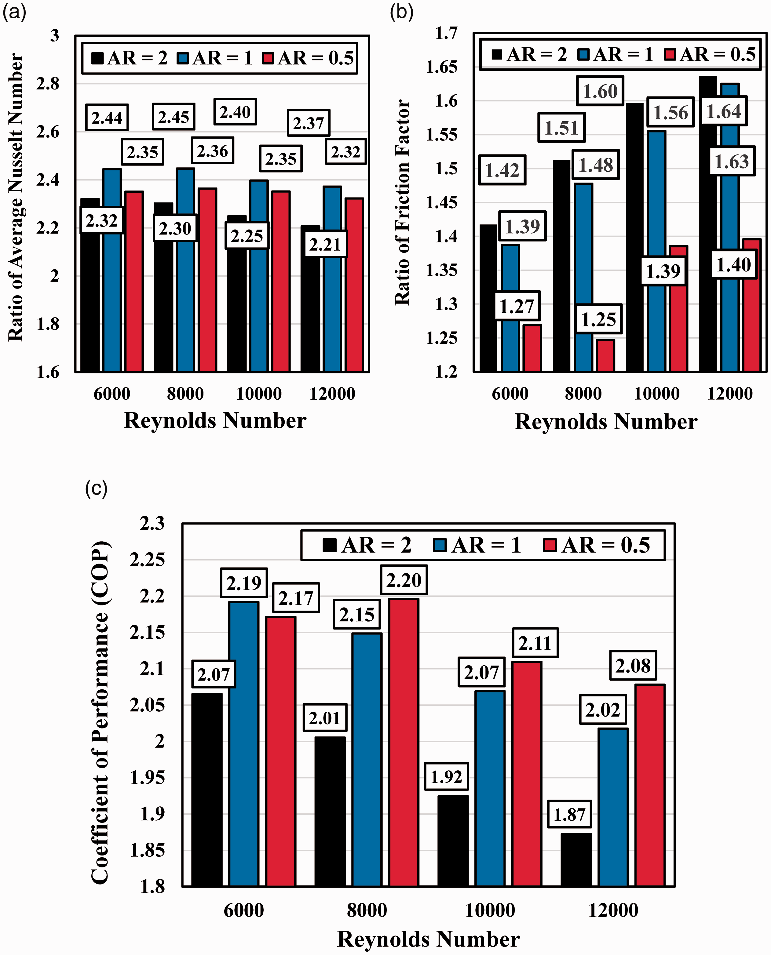
Variations of the (a) average Nusselt number ratio, (b) friction factor ratio, and (c) coefficient of performance (COP) for different aspect ratios (AR) of the ribs and Reynolds numbers.
Figure 24(a) shows that the case with AR = 1 has the highest average Nusselt number ratio and the lowest one is obtained for AR = 2. According to Figure 24(b), the highest friction factor ratio appears for AR = 2, while the case with AR = 0.5 exhibits the lowest friction factor ratio. Figure 24(c) shows that at relatively high Reynolds numbers (Re = 8000-12000), the highest and lowest COP are observed for AR = 0.5 and AR = 1, respectively. The contours of the velocity magnitude for various aspect ratios (AR) at Re = 12000 and Y = 1.5 mm are displayed in Figure 25. Accordingly, the secondary flows for cases AR = 1 and 2 are higher than for the case AR = 0.5, which induces a higher heat transfer rate.
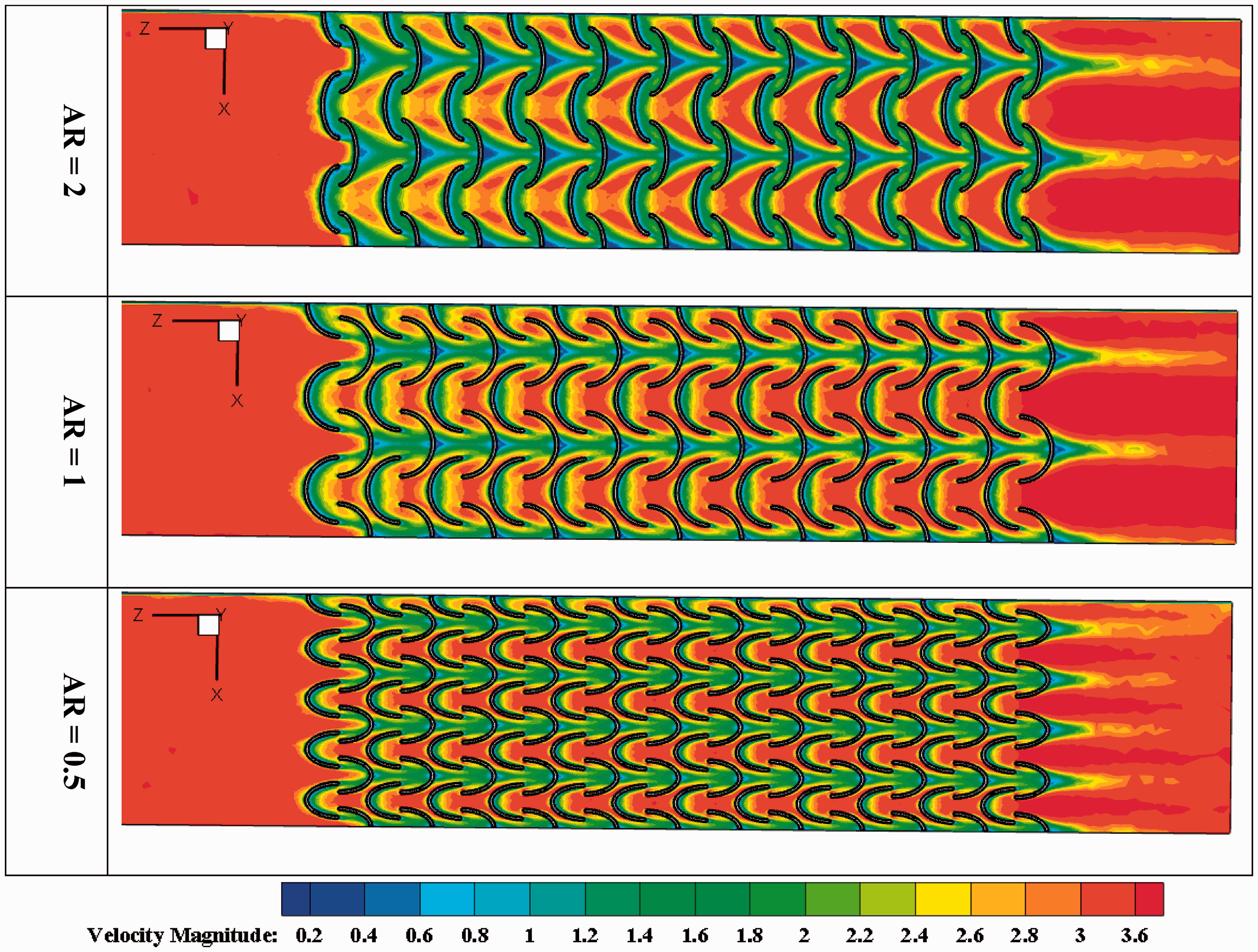
Contours of the velocity magnitude for various aspect ratios (AR) of the ribs for Re = 12000 and Y = 1.5 mm.
Correlations for the friction factor and Nusselt number
Based on the obtained results from the previous sections, the Nusselt number and friction factor are functions of three dimensionless geometrical parameters and Reynolds number. The considered dimensionless geometrical parameters include the aspect ratio (AR or r*), the dimensionless distance between the ribs (
In equation (17), a, b, c, d and e are constants. Finally, the correlation for the Nusselt number is given with a maximum error of 3.6%:
The correlation for the friction factor is obtained with a maximum error of 5.8%:
The above equations are applicable for the following geometrical and operational conditions:
Conclusions and future scope
Solar air heating is a solar thermal technology in which the energy from the sun is absorbed by a medium and utilized to heat air. In the present paper, a SAH equipped with innovative arc shaped ribs was considered. Actually, the objective of the present work was the evaluation of a solar air heater thermal performance in the presence of innovative arc-shaped ribs, which have never been considered previously in the literature. The heat transfer process in the studied SAH was investigated numerically using a commercial CFD code. The results were obtained for Reynolds numbers between 6000 and 12000. The effects of the rib cross section, the inter-rib distance, their aspect ratio and pitch on the thermal performance of the solar air heater were quantified. Results indicated that: Ribs with a quadrangular cross section exhibit the best coefficient of performance. Ribs with low pitch (here 40 mm) and aspect ratio equal to 0.5 show the highest thermal performance. The effect of the distance between the ribs on thermal performance of the proposed SAH is negligible. Two correlations are obtained for the average Nusselt number and friction factor based on the three geometrical parameters.
Although this study has provided new insight into the flow and thermal characteristics of a solar air heater combining innovative arc shape ribs, additional research is needed in order to demonstrate the viability of this design in more realistic engineering situations by the development of an experimental prototype.
Footnotes
Acknowledgements
S.P. acknowledges the NSERC chair on industrial energy efficiency established at Université de Sherbrooke in 2019 with the support of Hydro-Québec (laboratoire des technologies de l’énergie), Resources Canada (CanmetEnergy-Varennes) and Emerson Commercial and Residential Solutions.
Declaration of Conflicting Interests
The author(s) declared no potential conflicts of interest with respect to the research, authorship, and/or publication of this article.
Funding
The author(s) received no financial support for the research, authorship, and/or publication of this article.