
Abstract
Under the cutting loads of high efficiency and intermittent, the friction status between the tool flank and transition surface has time-varying characteristics, which directly affects friction and wear performance of the milling cutter. The dynamic distribution of instantaneous friction on tool flank under milling vibration needs to be revealed. In this work, the effect of milling vibration on instantaneous cutting contact relationship between milling cutter and workpiece was researched, a calculation method for the instantaneous friction velocity and friction energy consumption on tool flank was proposed. The variation of instantaneous friction between tool flank and transition surface under milling vibration was identified and evaluated by power spectral entropy and cross-correlation function. A method for identifying the unsteady friction of tool flank was proposed. The response analysis and experimental verification were conducted. The results showed that the frequency domain parameter distribution of friction energy consumption on tool flank had a strong correlation with the wear depth distribution, and was obviously sensitive to the milling parameters. The above models and methods could be used to reveal the influence of key milling process variables on unsteady friction and wear process of milling cutter’s multiple tool flank.
Keywords
Introduction
During the efficient milling of large titanium alloy components, there is intense friction between the milling cutter and the workpiece, and is affected by the impact of multiple teeth cutting into and out of the workpiece, resulting in a complex and uncertain process of milling cutter frictional wear, making it difficult to ensure its effective service life. This has become a technological bottleneck that restricts the improvement of milling efficiency and machining quality for large titanium alloy components.1,2
Studies on milling cutter frictional wear and service life reveal that the formation and evolution processes of milling cutter frictional wear morphology, wear topography, and wear volume are not only related to tool and workpiece materials, tooth and cutting edge structures, cooling and lubrication conditions, and process parameters, but also closely associated with the dynamic distribution state of the thermal-coupled field in the tool-work contact zone and the evolutionary behavior of instantaneous friction of the tool.3–5 To address this, a variety of physical indicators and analysis and evaluation methods for evaluating the degree of milling cutter wear have been proposed, and based on the law of friction, friction work, and friction coefficient model, using the structural parameters of the milling cutter and the cutting parameters of the milling cutter on the friction variables in the milling process of the friction characteristics of the milling cutter cutting process, to obtain the prediction of milling cutter wear and the optimization of process parameters, and to develop the prediction of the milling cutter service life method and the monitoring system.6–9 The above research points out the direction for revealing the friction and wear process of high-efficiency milling cutters and realizing the effective control of milling cutter service life.
During the cutting process of high-efficiency milling cutters, under the combined effect of factors such as intermittent cutting of cutter teeth, nonlinear fluctuation of cutting force, milling vibration, and cutter tooth error,10,11 the transient cutter-worker contact relationship of the milling cutter generates variability, which makes the transient thermal coupling field of the cutter teeth and the evolution of transient friction behavior have obvious non-steady state characteristics and the friction and wear characteristics of each cutter tooth of the milling cutter are not exactly the same.12–14 The use of steady-state analysis methods and empirical methods based on milling cutter wear experiments cannot correctly describe and identify the non-steady-state frictional wear processes of high-efficiency milling cutters, resulting in the actual service life of milling cutters being much less than the predicted minimum service life.15,16 To solve this problem, it is necessary to construct a solution model that can correctly characterize the instantaneous contact relationship and instantaneous friction variables under the combined influence of multiple factors, so as to realize the effective correlation between the initial process variables of milling, the cutting process variables and the unsteady friction and wear characteristics of multiple teeth of the milling cutter.
Frictional wear on the flank face of the tooth is an important basis for studying and evaluating the service life of high-efficiency milling cutters. When compared to the frictional wear on the rake face of the tooth, the frictional wear on the flank face has a more significant influence on cutting forces and the quality of high-efficiency milling. Additionally, the friction behavior between the flank face of the tooth and the machined transition surface is essential for understanding the tool-work contact relationship in the third deformation zone of high-efficiency milling. Therefore, it is necessary to study this aspect.
The instantaneous friction behavior of the flank face of each tooth on the high-efficiency milling cutter is not only correlated with its historical behavior but also follows the changing states, exhibiting non-steady-state and non-linear characteristics.17,18 Due to the frequent variation of cutting loads and the influence of milling vibrations, the instantaneous cutting behavior of the tooth is in an unstable state, and the transient contact relationship between the flank face and the machined transition surface of the workpiece is constantly changing, leading to the multi-time-variable and chaotic characteristics of the instantaneous tool-work contact position, friction velocity, and frictional energy consumption of the flank face. 19 Previous research on frictional wear of milling cutter flank faces has assumed that the instantaneous cutting behavior and flank face frictional behavior of each tooth have identical variation characteristics. However, by disregarding factors such as milling vibrations and tooth errors that result in variations in the instantaneous cutting behavior of individual teeth due to their combined effects, and the variability in the distribution of the flank face frictional behavior, the current calculations for the instantaneous friction behavior of the tooth’s flank face are inadequate, leading to an incomplete revelation of the non-steady-state frictional characteristics of the high-efficiency milling cutter’s flank face.
The time-frequency characteristics of instantaneous friction velocity and frictional energy consumption at different positions on the tooth’s flank face are key to calculating and identifying the dynamic distribution characteristics of non-steady-state frictional behavior on the milling cutter’s flank face.20,21 Moreover, utilizing power spectra and cross-correlation functions of the instantaneous friction behavior on the tooth’s flank face enables the quantitative estimation of the chaotic characteristics of the instantaneous friction behavior on the milling cutter’s flank face during the entire cutting period, along with its sensitivity to milling vibrations.4,22,23 To address this, this paper focuses on the impact of milling vibrations and tooth errors on the milling cutter and its tooth’s instantaneous cutting posture. An instantaneous friction variable calculation model for the tooth’s flank face is established. Based on milling vibration experiments and analysis of the thermal-coupled field of the tooth, the time-frequency characteristics of instantaneous friction velocity and frictional energy consumption on the flank face are obtained. Power spectral entropy and cross-correlation functions are utilized to reveal the dynamic distribution characteristics of non-steady-state friction on the tooth’s flank face under the influence of milling vibrations. This achieves an effective correlation between non-steady-state friction on the tooth’s flank face and process variables in high-efficiency milling. Additionally, response characteristic analysis and tooth wear experiments are conducted for validation.
The instantaneous position and contact angle of milling cutter under vibration
Tooth error and milling vibration directly affect the instantaneous position and contact angle of the milling cutter, and then change the instantaneous contact \right)relationship between tool flank and machining transition surface. The structure of the high-feed milling cutter and its cutter contact relationship is shown in Figures 1 and 2. The meaning of each variable is shown in Appendix 1.

High feed milling cutter structure.

Instantaneous contact relationship between milling cutter and workpiece.
From Figures 1 and 2, the instantaneous position of the milling cutter and its teeth under milling vibration is shown in Figure 3.

Milling cutter and tooth position: (a) milling cutter position and (b) tooth position.
According to Figures 2 and 3, Φi can be calculated. The specific derivation process is detailed in Appendix 2. The contact angle of the cutter tooth cut in and cut out the workpiece under vibration is shown in Figure 4:

The contact angle of the cutter tooth under vibration.
In Figure 4, a0 is the intersection point between the cutter and the workpiece when the cutter cut into; a1 is the intersection point between the cutter and the workpiece when the cutter cut out; x0(t0) and y0(t0) are the horizontal and vertical coordinates of the origin of the milling cutter coordinate system in the workpiece coordinate system when the cutter cut into; x0(t1) and y0(t1)are the horizontal and vertical coordinates of the origin of the milling cutter coordinate system in the workpiece coordinate system when the cutter cut out.
From Figure 4, the cutter tooth cut into the workpiece at position a0 and its characteristic time of cutting into the workpiece is


Where gi(x(t), y(t), z(t)) is the cutting edge trajectory of tooth i; gi(xi, yi, zi) is the cutting edge equation; x(t0) is the horizontal coordinate of tooth cut into the workpiece relative to the workpiece coordinate system at t0; tT is the start time of a cycle; tT + Δt is the end time of a cycle.
The cutter tooth cut out the workpiece at point a1 and its characteristic time is


Where gi−1(xi−1, yi−1, zi−1) is the cutting edge equation of the cutter i−1; Gi−1 (x(t′), y(t′), z(t′)) is the transition surface equation formed by the cutting edge of tooth i−1 in the workpiece coordinate system; x(t1) is the horizontal coordinate of the cutter workpiece relative to the work coordinate system at t1.
Then from equations (1) to (4), the contact angle of the cutting edge of tooth i when cutting in the workpiece can be expressed as:

The contact angle of the cutter i cutting edge can be expressed as:

As can be seen from the above, during the process of tooth cutting into and cutting out the workpiece, under tooth error and milling vibration, the transient position of the milling cutter and its tooth is a non-stationary bias. The transient contact relationship of the cutter would change, which would directly change the instantaneous friction behavior of the tool flank and machining transition surface.
Instantaneous friction variables on tool flank and its time domain variation
Based on Figures 2 and 3, under vibration and cutter tooth error, the instantaneous contact relationship between the cutter tool flank and the processing transition surface is shown in Figures 5 and 6.

Instantaneous geometry relationship between tool flank and processing transition surface.

Friction velocity and stress on the tool flank.
In Figure 5 and equation (1), the processing transition surface equation formed by the cutting edge of tooth i is:

The instantaneous location and posture and relative velocity component of tool flank of the cutter tooth in the workpiece coordinate system is:

The instantaneous friction velocity of the contact point on the tool flank and processing transition surface is:

In the equation, v(t) is the instantaneous relative motion speed of the tool flank.
Using the energy conversion relationship between the atoms at the tool interface, the friction energy consumption is 24 :


In the equation, ds is the infinitesimal area of the tool flank; ω is the atomic forced vibration frequency; a is the lattice constant (2.95 × 10⁻¹⁰ m); h is Planck constant (h = 6.62 × 10⁻³⁴ J s); k is Boltzmann constant (k = 1.38 × 10⁻²³ J/K); T(t) is the atomic interface temperature; m is the relative atomic mass of 4.34 × 10⁻²⁶ kg; ωn is the atomic natural frequency of 4.39 × 10¹¹ rad/s; Q is the interface potential energy field excitation force pair of 1.00 × 10⁻⁹ N; vmi (xi, yi, zi, t ) is the friction velocity in the cutter coordinate system at any point t on tool flank of the cutter.
Based on Figure 6, the normal pressure of the frictional contact point and friction coefficient are:

In the equation, σ(t) is the instantaneous stress on the tool flank, μ(t) is the instantaneous friction coefficient, ψ(t) is the angle between the instantaneous normal vector and the instantaneous stress direction vector on the tool flank.
It is assumed that the friction work is completely converted into the heat energy of the system during the friction movement of the tool interface. According to equations (10) and (13), the instantaneous friction coefficient on the tool flank is:

The friction studied in the above model is mainly aimed at the friction on the flank face, ignoring the temperature change and extrusion on the rake face and the change of the blade shape. From the above, it could be seen that under milling vibration, the instantaneous friction velocity and instantaneous friction energy consumption at the contact point between the flank and processing transition surface had nonlinear and unsteady characteristics. Due to its influence, the instantaneous friction coefficient and instantaneous friction stress at the contact point of the cutting tool continuously changed, resulting in a complex and variable friction process on the tool flank of the cutting tool teeth.
To this end, the above models were used, combined with the milling cutter and its cutting titanium alloy process conditions provided by the enterprise, to conduct milling vibration experiments and solve the instantaneous friction velocity and instantaneous friction energy consumption contact point on the tool flank. Among them, the milling cutter was a hard alloy indexable high feed milling cutter with a diameter of 32 mm. The diameter of the inscribed circle of the cutter tooth d is 9.52 mm, the radius of the corner of the tool tip r is 1.2 mm, the thickness of the blade s3 is 3.97 mm, and the main back angle α3 is 14°. The axial length and milling radius of the cutter tooth are measured by the tool setting instrument. The axial distance from the lowest point of the cutter tooth to the end face of the milling cutter is defined as the axial reference, and the maximum milling radius of the cutter tooth is defined as the radial reference.
The cutting parameters and tool tooth error detection results are shown in Table 1. Among them, Scheme 1 and Scheme 2 maintain consistent cutting efficiency with a cutting stroke of 2.5 m. In order to ensure that the experimental results are consistent and universal, all the workpieces used in the experiment come from the same brand and batch. The principle of cutting parameters selected in Table 1 is to ensure the machining accuracy and surface roughness of the workpiece, give full play to the cutting performance of the tool, ensure the service life of the tool, maximize productivity, and reduce costs.
Milling cutter tooth error distribution.

The axial error and radial error of high feed milling cutter teeth are measured by using the tool setting instrument. The axial error of milling cutter teeth is measured based on the maximum axial distance from the lowest point of milling cutter teeth to the end face of milling cutter. The radial error of milling cutter teeth is measured based on the maximum radius from the tip point of milling cutter teeth to the axis of milling cutter.
The milling cutter is in the process of cutting into cutting out the workpiece. The charge output PCB three-axis acceleration sensor is used to detect the vibration acceleration signal in the milling process. The sensitivity of the sensor is 25 mV/g, and the range is 0.5–6.5 Hz. The DH5922 transient signal test and analysis system is used to collect the milling vibration acceleration data between the sensor and the spindle, as shown in Figure 7.
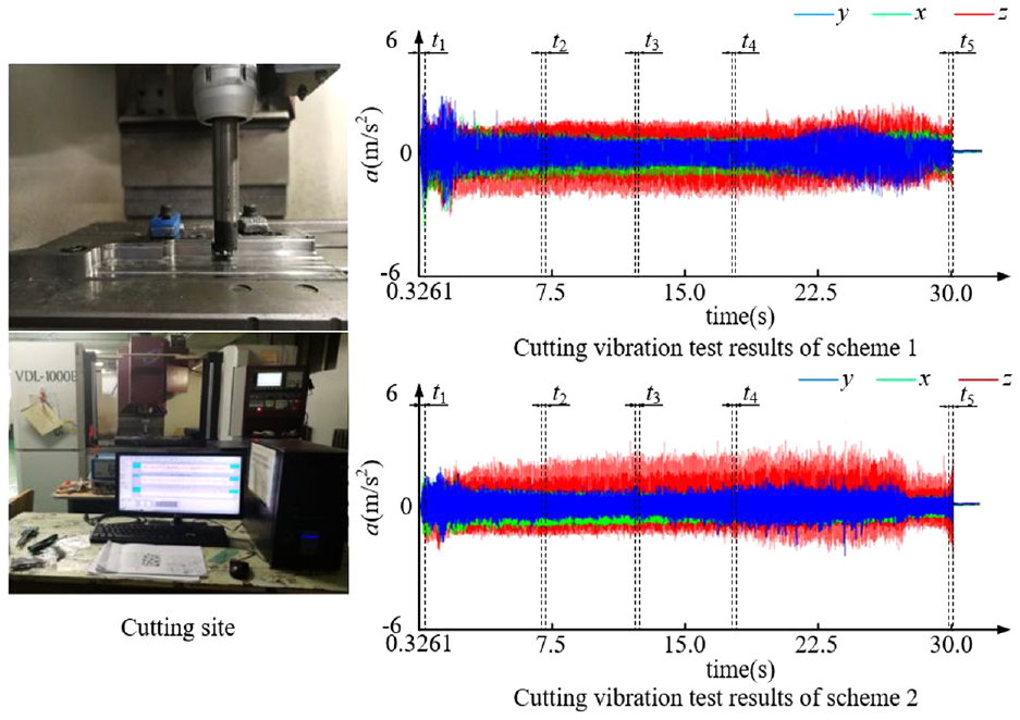
Milling experiment and vibration acceleration signal.
Using experimental scheme 1 in Table 1 and the experimental results of milling vibration, the finite element model and boundary conditions of high-feed milling cutter cutting titanium alloy were constructed using equations. The formula in Appendix 2 and (1)–(6) to obtain the results of the thermal coupling field analysis of the cutter teeth. The finite element simulation boundary conditions are set in the pre-processing module of Deform-3D, which is consistent with the experimental milling parameters. The finite element mesh is divided, and the mesh type is selected as the tetrahedral structure. The thermal coupling field simulation of the flank face of the cutter tooth is carried out. After the simulation is completed, the post-processing module is entered. Among them, the equivalent force and equivalent variation for the 221st cutting cycle of tool tooth 1 with a contact angle of 45° are shown in Figures 8 and 9.

Stress-effective distribution of the tool flank.

Strain rate distribution of the tool flank.
From Figures 8 and 9, the cutting edge after frictional wear was obtained using the cutting edge yield strength of the cutter tooth to determine the frictional upper boundary of the tool flank at the current moment. The mutation rate of the equivalent effect variation along the cutting edge normal vector direction was used to identify the lower boundary of the flank tool surface friction at the current moment, as shown in Figure 10. Among them, the coordinates of the toolwork contact points e1, e2, and e3 of the flank in the cutter tooth coordinate system are: e1 (3.62, 6.08), e2 (3.72, 6.08), and e3 (3.82, 6.08), respectively.

Transient friction boundary and feature point selection of the flank.
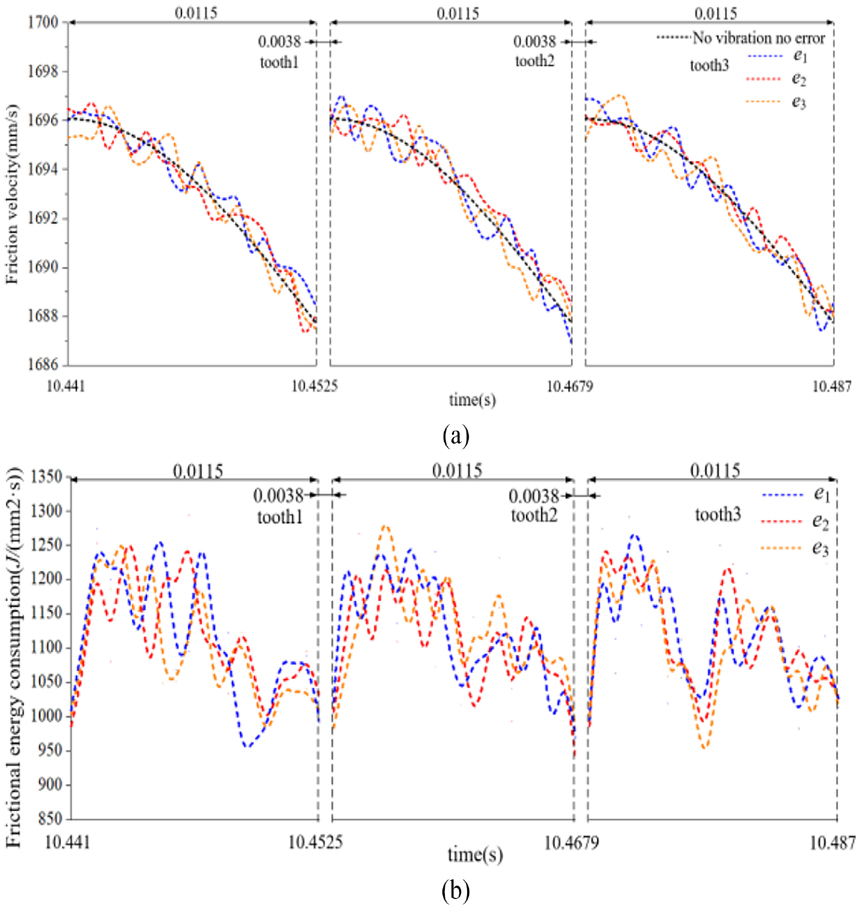
Using the above method, the instantaneous frictional characteristics variables of the tool flank in Scheme 1 were obtained. Among them, the time domain variation characteristics of the instantaneous frictional velocity and instantaneous frictional energy consumption of the tool flank after the 221st cutting cycle of the milling cutter, three cutter teeth, are shown in Figure 11.

Time domain variation of instantaneous frictional characteristic variables of the flank: (a) instantaneous friction speed and (b) instantaneous frictional energy consumption.
As shown in Figure 11, the friction velocity and friction energy consumption have different fluctuation degrees with the change of time. This is due to the change of vibration with time, which causes the instantaneous contact between the flank surface of the cutter tooth and the machining transition surface and the change of the thermo-mechanical coupling field in the contact area. However, it can be clearly seen that the instantaneous change of friction velocity fluctuates up and down on the curve without vibration and error, and the overall trend is basically unchanged.
The results of the comparative analysis of instantaneous friction speed and instantaneous friction energy consumption RMS value and kurtosis. For different cutting cycles of the milling cutter from cutting into to cutting out of the workpiece, different tool work contact points on the tool flank of the three cutter teeth, are shown in Figures 12 and 13. Where the milling cutter cutting cycles are the 1st, 136th, 221st, 311th, and the last cutting cycle, that is, the 552nd cycle.

Frictional velocity time domain characteristic parameters: (a) root mean square value and (b) Kurtosis.

Frictional energy consumption time domain characteristic parameters: (a) root mean square value and (b) Kurtosis.
From Figures 11 to 13, the frictional velocity and frictional energy consumption of different tool contact points on the tool flank surface of the three cutter teeth in the same milling cutter cutting cycle, although their overall trends were similar, there were significant differences in their transient distribution. The root-mean-square value and the kurtosis of the friction velocity of the flank were in an unstable state from the cutting cycle of the milling cutter to the cutting cycle of the workpiece, and the change of the position of the cutter teeth and the flank showed different characteristics. Although the variation of the root mean square values of instantaneous frictional energy consumption were relatively little different, their kurtosis variation was significantly different.
The results showed that the instantaneous friction behavior of each tool flank and the machined transition surface, influenced by milling vibration, showed different variation characteristics with the transient position and contact angle of the tool tooth. Using the above model and method, the time domain distribution of unsteady friction on the tool flank could be identified. At the same time, it was found that the impact components in the frictional velocity and frictional energy consumption of the flank tool surface had obvious multi variability. And it is necessary to do further identification of their frequency domain characteristics.
Frequency domain analysis of unsteady friction on tool flank
According to the time domain analysis results of the friction variables of each tool flank, the friction velocity and friction energy consumption spectrum and power spectrum of different cutter contact points on the three tool flanks in scheme 1 were obtained by Fourier transform. The unsteady characteristics in the frequency domain were revealed. Among them, the milling cutter 221 cutting cycle, three tool flank friction speed, and friction energy consumption spectrum and power spectrum are shown in Figures 14 to 17.
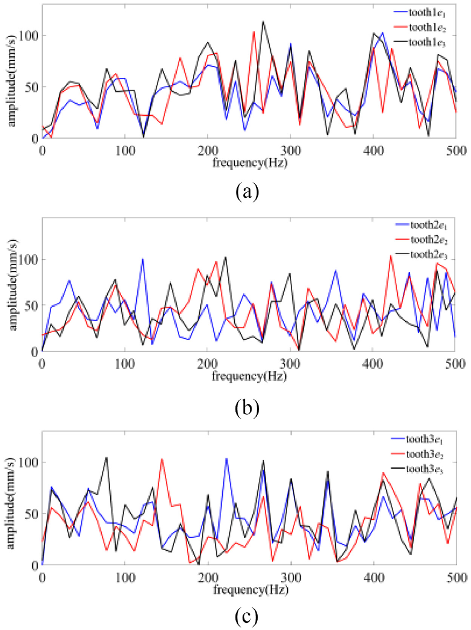
Friction velocity spectrum of tool flank: (a) tooth 1, (b) tooth 2, and (c) tooth 3.

Power spectrum of tool flank friction velocity: (a) tooth 1, (b) tooth 2, and (c) tooth 3.
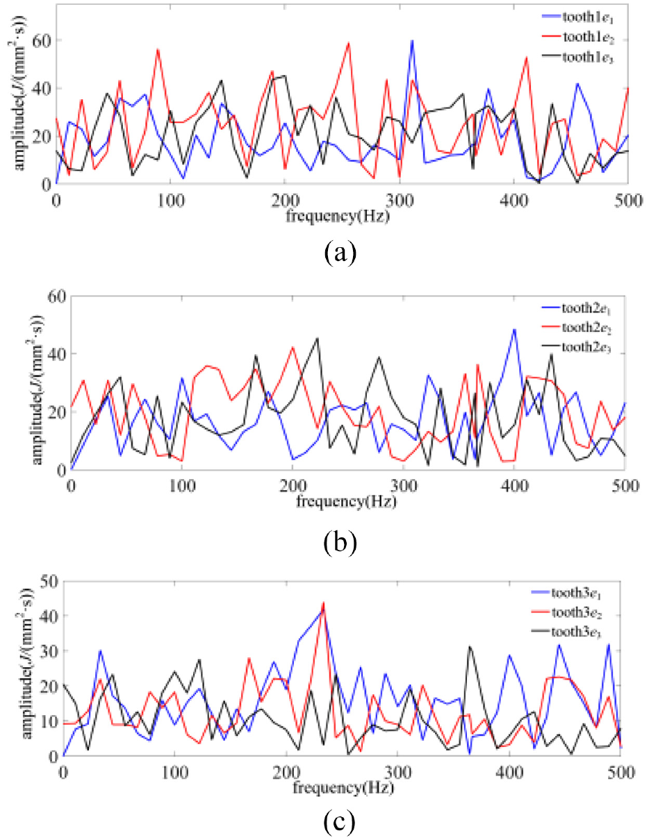
Friction energy consumption spectrum of tool flank: (a) tooth 1, (b) tooth 2, and (c) tooth 3.

Power spectrum of tool flank friction energy consumption: (a) tooth 1, (b) tooth 2, and (c) tooth 3.
From Figures 14 to 17, the friction velocity and friction energy spectrum and power spectrum at different positions on the tool flank of the three cutter teeth showed a diversified distribution in the range of 0–500 Hz, showing obvious unsteady friction characteristics. The results showed that in the same milling cutter cutting cycle, the milling vibration corresponding to the characteristic time of each tooth cutting in and cutting out workpiece changes the frequency domain distribution of the instantaneous friction of the cutter tool flank.
The spectral characteristic parameters and power spectral entropy of different cutting cycles from the cutter to the workpiece were extracted, as shown in Figures 18 and 19.

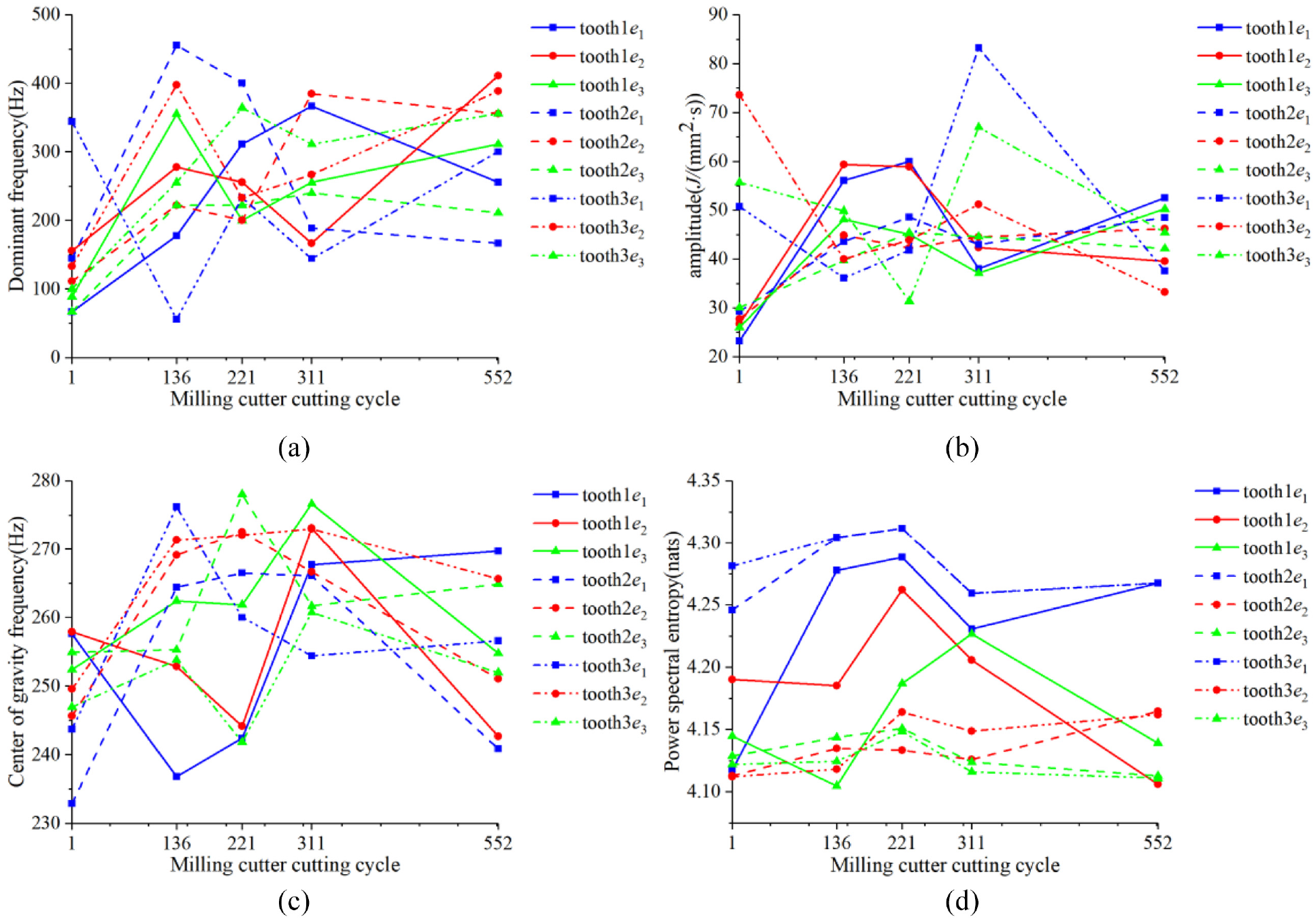
Frequency spectrum characteristic parameters and power spectrum entropy of tool flank friction velocity: (a) dominant frequency, (b) amplitude, (c) center of gravity frequency, and (d) power spectral entropy.
Spectrum characteristic parameters and power spectrum entropy of tool flank friction energy consumption: (a) dominant frequency, (b) amplitude, (c) center of gravity frequency, and (d) power spectral entropy.
In the process of cutting into and cutting out the workpiece, the dominant frequency, amplitude, center of gravity frequency, and power spectrum entropy of the friction velocity and friction energy consumption spectrum of each cutter tool flank showed obvious variability. Among them, the dominant frequency changing in a large range, and the continuous change of the overall spectrum balance value and spectrum intensity represented by the center of gravity frequency and amplitude directly reflected the unsteady characteristics of the friction process of the tool flank; The large change of the main frequency of the friction velocity is due to the instability of the instantaneous contact angle caused by the vibration. The large change of the main frequency of the friction energy consumption is due to the multi-parameter change of the friction velocity and the thermal-mechanical coupling field. Although the variation range of power spectral entropy was not large, its level and instability reflect the randomness of the friction process of the tool flank.
The above analysis results showed that factors such as cutter tooth error and milling vibration impact not only make the unsteady friction characteristics of each tool flank significantly different, but also aggravate the complexity and uncertainty of the nonlinear friction process of the tool flank.
Therefore, the cross-correlation function was used to analyze the mutual matching degree of the spectrum of milling vibration and the friction of the tool flank in different cutting cycles. Among them, the milling cutter 221 cutting cycle, milling vibration and tool flank friction speed, friction energy consumption correlation coefficient are shown in Figures 20 and 21.

Milling vibration and friction velocity cross-correlation coefficient: (a) tooth 1, (b) tooth 2, and (c) tooth 3.

Milling vibration and friction energy consumption correlation coefficient: (a) tooth 1, (b) tooth 2, and (c) tooth 3.
From Figures 20 and 21, the correlation coefficient between milling vibration and friction velocity and friction energy consumption of each tool flank changes periodically. In the initial stage of the cutter tooth cutting into the workpiece, the milling vibration along the three directions of the milling cutter feed, cutting width, and cutting depth was less different from the cross-correlation coefficient of the flank friction, indicating that the unsteady friction of the flank of the cutter tooth at this stage was affected by the impact of the cutter tooth cutting in the above three directions.
At the same time, it was found that in the main cutting stage of the cutter teeth, the absolute value of the cross-correlation coefficient between the vibration along the cutting width direction of the milling cutter and the friction of the flank surface was significantly larger than that along the feed direction of the milling cutter, and the absolute value of the cross-correlation coefficient along the cutting depth direction of the milling cutter was the smallest.
The maximum value of the correlation coefficient between the milling vibration and the friction of the flank surface changes with the milling cycle, as shown in Figures 22 and 23.

The maximum cross-correlation coefficient between milling vibration and friction velocity varies with milling cycle: (a) tooth 1, (b) tooth 2, and (c) tooth 3.

The maximum value of the correlation coefficient between milling vibration and friction energy consumption varies with the milling cycle: (a) tooth 1, (b) tooth 2, and (c) tooth 3.
It can be seen from Figures 22 and 23 that although the cross-correlation coefficients between the milling vibration in the three directions and the friction of each tool flank showed different characteristics with the milling period, the cross-correlation coefficient along the cutting width direction of the milling cutter was obviously larger than that in the other two directions. The results showed that the frequency domain characteristics of the friction velocity and friction energy consumption of the tool flank were mainly affected by the vibration along the cutting width direction of the milling cutter.
Unsteady friction identification and its response analysis on tool flank
Based on the above analysis results, the identification method of unsteady friction for the tool flank was proposed, as shown in Figure 24.

Identification method of unsteady friction of tool flank.
Aiming at the variability of the instantaneous cutting behavior of the milling cutter and cutter tooth under milling vibration and cutter tooth error, the instantaneous friction velocity and instantaneous friction energy consumption calculation model of the tool flank and the machining transition surface were used to reveal the time-frequency variation of the flank friction of the milling cutter. The uncertainty of the unsteady friction process of the flank was quantitatively characterized by power spectrum entropy. The cross-correlation function was used to identify the influence of milling vibration in the direction of the cutting parameter characteristic vector on the unsteady friction process of the tool flank.
Aiming at the variability of the instantaneous cutting behavior of the milling cutter and cutter tooth under the action of milling vibration and cutter tooth error, this method uses the instantaneous friction velocity and instantaneous friction energy consumption calculation model of the flank surface of the cutter tooth and the machining transition surface to reveal the time-frequency variation characteristics of the flank friction of the milling cutter. The uncertainty of the unsteady friction process of the flank face is quantitatively characterized by power spectrum entropy. The cross-correlation function is used to identify the influence of milling vibration in the direction of the cutting parameter feature vector on the unsteady friction process of the flank face of the milling cutter.
In order to verify the effectiveness of the method, using scheme 2 in Table 1 and its milling vibration experimental results, the method of Figure 24 was used to identify the unsteady friction characteristics of the tool flank, and the results were compared with the results of scheme 1.
Among them, the time-domain variation of the instantaneous friction velocity and instantaneous friction energy consumption of the three cutter flanks in the 221st cutting cycle of the milling cutter in scheme 2 is shown in Figure 25.
Time domain variation of instantaneous friction characteristic parameters of tool flank: (a) instantaneous friction velocity and (b) instantaneous friction energy consumption.
The frequency domain characteristic parameters of friction velocity and friction energy consumption of the tool flank of the two schemes were compared in different cutting cycles from the cutter to the workpiece, as shown in Figures 26 and 27. Among them, the position of each tool flank is the cutter contact point e1 in Figure 25.

Comparison of friction velocity frequency domain parameters: (a) dominant frequency, (b) amplitude, (c) center of gravity frequency, and (d) power spectral entropy.

Comparison of frequency domain parameters of friction energy consumption: (a) dominant frequency, (b) amplitude, (c) center of gravity frequency, and (d) power spectral entropy.
Comparing Figures 11 and 25, there are some differences in the time-domain variation of the friction characteristic variables of the tool flank under the two process schemes, but they generally show similar variations, which were mainly related to the use of milling cutters with the same number of cutter teeth in the two schemes. Compared with scheme 1, the friction speed level of scheme 2 was improved, but the friction energy consumption level was reduced, which was mainly related to the increase of milling cutter speed and the decrease of feed per tooth, which changes the distribution of thermal-mechanical coupling field on tool flank of cutter teeth.
From Figures 26 and 27, it can be seen that there were obvious differences between the two process schemes in the changes of characteristic parameters such as the dominant frequency, spectrum amplitude, center of gravity frequency, and power spectrum entropy of the friction on the tool flank of the milling cutter. It showed that the calculation results of the frequency domain characteristics of the friction characteristic parameters on tool flank of the milling cutter were highly sensitive to the process variables such as milling cutter speed, cutter tooth error, and milling vibration, which could be used to evaluate the high-efficiency milling process scheme.
Experimental verification
The two process schemes and experimental methods in Table 1 were used to conduct wear experiments on the tool flank of milled titanium alloy TC4. The white light interferometer was used to obtain the results of the wear profile inspection of each tool flank, as shown in Figures 28 and 29.
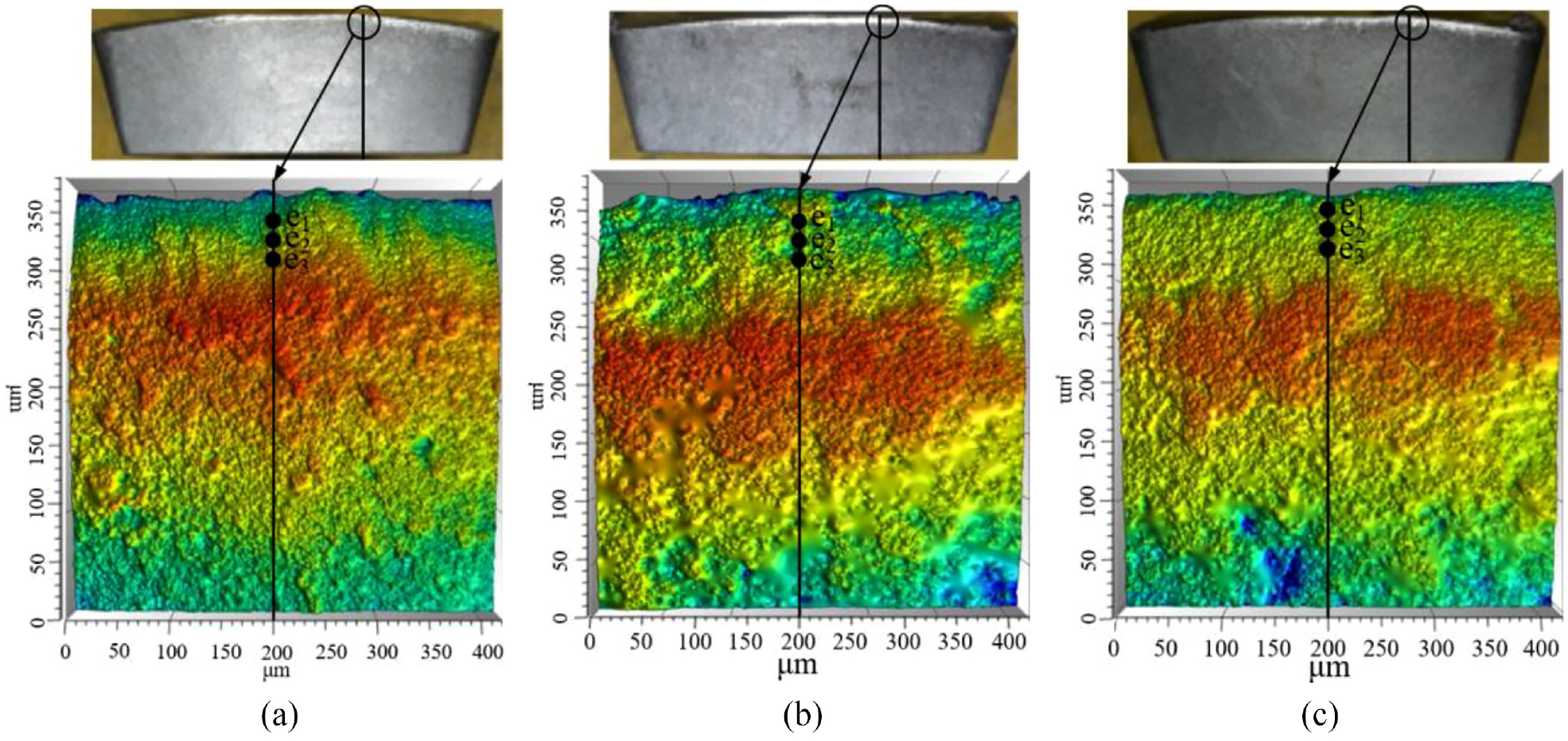
Experimental results of tool flank wear for Scheme 1: (a) tooth 1, (b) tooth 2, and (c) tooth 3.
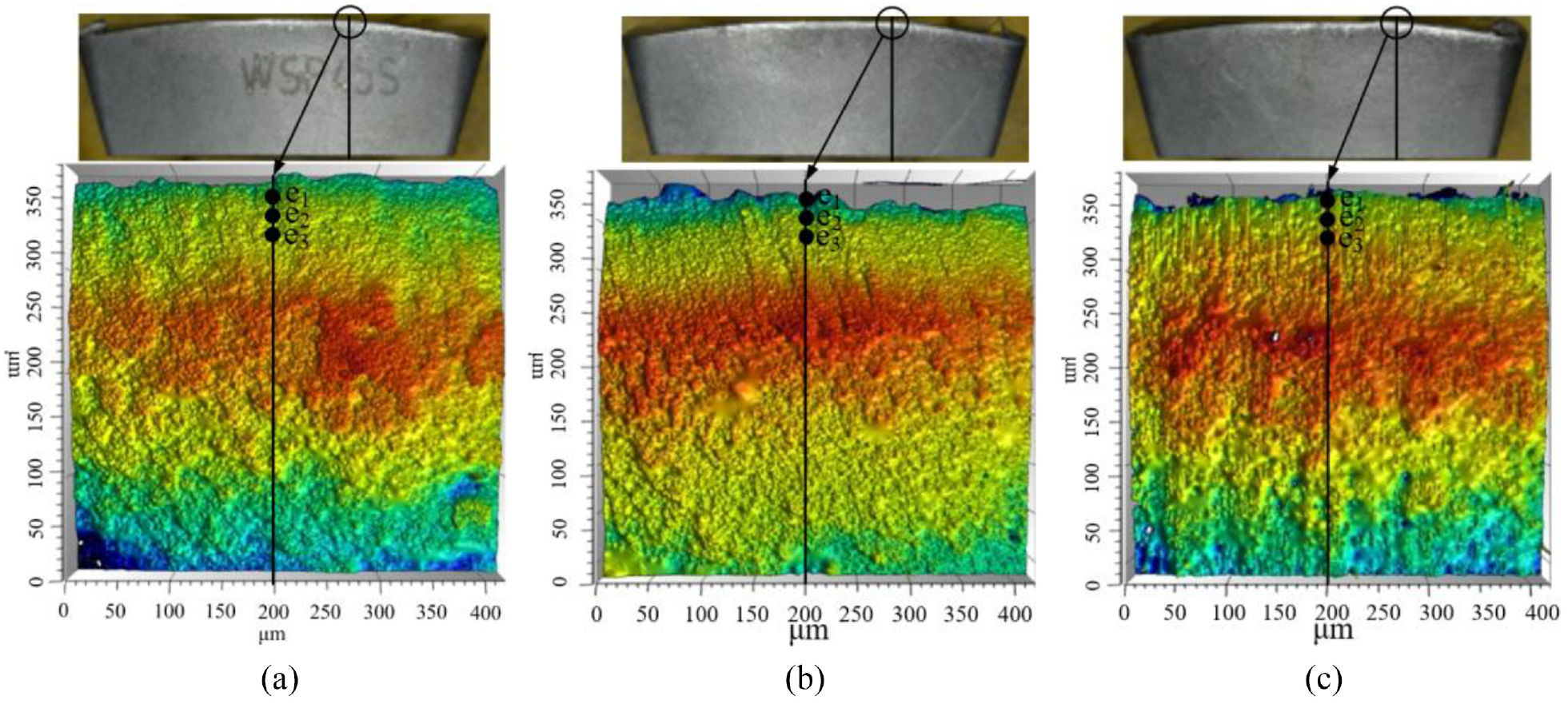
Experimental results of tool flank wear for Scheme 2: (a) tooth 1, (b) tooth 2, and (c) tooth 3.
Comparing Figures 7, 28, and 29, it can be seen that when the tool tooth error and milling tool speed change, milling vibration then changed and made the wear profile of the tool flank significantly different for the two solutions. It was also found that there was a difference in the wear of each tool flank. The results showed that the two tool flank experienced different frictional wear processes, and there were multiple frictional wear evolution characteristics for each tool flank.
Based on the morphological cross-sectional curves before and after the wear of each point on the tool flank in Figures 28 and 29, the correlation coefficient γ was obtained, and the unevenness of the wear of each point on the tool flank was judged by 1−γ. The results of the frequency domain analysis of the frictional energy consumption of the tool flank were used to evaluate the non-stationary frictional characteristics of the tool flank. Using the positive correlation property between frictional energy consumption and wear, experimental verification was performed and the analytical results of the two scenarios are shown in Table 2. Where, W1 is the dominant frequency variation range, W2 is the spectrum amplitude variation range, W3 is the center of gravity frequency variation range, W4 is the power spectrum entropy variation range, and W5 is the power spectrum entropy maximum.
Frequency domain parameters and experimental analysis results of frictional energy consumption on the tool flank.

As can be seen from Table 2, under the two process schemes, except for the maximum value of power spectrum entropy for scheme 2 cutter tooth 3. As the friction contact point of the tool flank moves down, the wear inhomogeneity of the flank and the dominant frequency of friction energy consumption, spectral amplitude, center of gravity frequency, power spectrum entropy change range, and the power spectrum entropy maximum of other cutter teeth showed similar change characteristics. This result proved that the wear inhomogeneity of the tool flank was closely related to the frequent changes of the non-stationary frictional frequency domain characteristics of the flank; At the point near the cutting edge, the wear inhomogeneity is more obvious; at the point away from the cutting edge, the wear inhomogeneity is smaller, and similar results are shown on different cutter teeth.
Compared with Scheme 2, the degree of variation of the frequency domain parameters of the frictional energy consumption and the wear non-uniformity of the tool flank of Scheme 1 were at a relatively high level. The range of power spectrum entropy variation was smaller, but its maximum value was significantly higher than that of Scheme 2. This result showed that by increasing the milling cutter speed and changing the cutter tooth error, the non-stationary friction of the tool flank was improved and the unevenness of the flank wear was reduced.
Using the analysis results of the characteristic points of the flank of each tooth corresponding to the serial numbers 1–9 in Table 2, the frequency domain parameters of the frictional energy consumption at each point were used as the reference sequence to solve the correlation between the frequency domain variation characteristics of the frictional energy consumption of the flank and the wear inhomogeneity, as shown in Table 3.
Correlation between the frequency domain variation of the frictional energy consumption of the flank and the wear non-uniformity.

As can be seen from Table 3, changing the process scheme caused a response in the wear inhomogeneity of the tool flank and the friction energy consumption spectrum amplitude and power spectrum entropy correlation. It was also found that the correlation between the unevenness of wear on the tool flank and the variation of the main frequency of friction energy consumption was greater than 0.700, and the correlation with the variation of the center of gravity frequency was greater than 0.850, which was a strong correlation and a positive correlation. This indicated that the variation of the main frequency and spectral distribution of the non-stationary frictional energy consumption on the tool flank was the main reason for the unevenness of the wear on the tool flank.
The above analysis results showed that the model and method constructed in this paper could be used to identify the non-stationary friction characteristics of the tool flank under different process scheme conditions, and revealed the influence of spindle speed, tool tooth error, milling vibration, and other factors on the non-stationary friction process and wear unevenness of the flank.
Conclusions
The instantaneous posture and contact angle of the milling cutter were researched, the influence of cutter tooth error and milling vibration on the instantaneous contact relationship of the milling cutter was revealed. The results showed that the non-stationary bias of the transient position of the milling cutter during the cutting process made the transient contact relationship in an unstable state.
A model for the instantaneous friction variables on the tool flank was established. The results showed that the fundamental reason for the change of the distribution state of the thermal coupling field between the tool and the workpiece is that the vibration displacement of the tool leads to the change of the contact relationship between the flank face of the tooth and the machining transition surface and the friction velocity and friction energy consumption of the tooth flank is different in the frequency domain, which reason is that the different time domain characteristics of the friction velocity and friction energy consumption of the flank of different cutter teeth under the action of vibration and cutter tooth error.
A method for identifying the unsteady friction characteristics on the tool flank was proposed, which quantitatively characterized the variation and uncertainty on tool flank from the cutting-in to the cutting-out period; Cutting vibration is the root cause of the large change of the main frequency of the friction velocity on the flank surface and the machining transition surface of the milling cutter. The results showed that the above method could effectively identify the unsteady friction characteristics on the tool flank under milling vibration and its responses to different process parameters.
The results of the milling experiments and correlation analysis showed that the wear inhomogeneity on the tool flank was positively correlated with the frequent changes, and was strongly sensitive to the changes in dominant frequency and the center of gravity frequency. At the point near the cutting edge, the wear inhomogeneity is more obvious; at the point away from the cutting edge, the wear inhomogeneity is smaller. Using the above models and methods, the non-stationary friction characteristics and wear unevenness of the tool flank could be effectively improved by regulating variables such as milling cutter speed, tool tooth error, and milling vibration.
Footnotes
Appendix 1

| Variable symbol | Meaning of variable |
|---|---|
| oi-xiyizi | Milling cutter tooth coordinate system. |
| o 0′−x0′y0′z0′ | The milling cutter coordinate system without vibration effect. |
| o 0-x0y0z0 | The milling cutter coordinate system. |
| ov-xvyvzv | The milling cutter cutting coordinate system. |
| o-xyz | The workpiece coordinate system. |
| xL | Length of the workpiece |
| yL | Width of the workpiece |
| zL | the height of the workpiece |
| vf | Milling cutter feed speed |
| n | Milling cutter speed |
| ap | cutting depth |
| ae | cutting width |
| t | cutting time |
| φi(t) | The angle between yv axis and y0′ axis at time t |
| rmax | Milling cutter tooth tip maximum radius of gyration |
| Δzi | Axial error of milling cutter tooth i and cutter tooth i + 1 |
| Δri | The radial error of milling cutter tooth i and cutter tooth i + 1 |
| l 1 | The distance between the lowest point of the cutter tooth and the upper end face of the handle |
| li | The distance between the lowest point of the cutter tooth i and the upper end face of the handle |
| s 0 | The distance from the installation plane of the cutter tooth to the tip of the cutter tooth |
| s 1 | The distance from the cutter tooth installation plane to the lowest point of the cutter tooth cutting edge |
| s 2 | The distance between the two tip points of the cutter tooth |
| ηi | The angle between the line connecting the origin of the cutter tooth coordinate system and the origin of the milling cutter coordinate system and the line connecting the two tool tip points |
| α 0 | The angle between zi axis of cutter tooth coordinate system and z0 axis of milling cutter coordinate system. |
| α 1 | The angle between the line connecting the two tool tip points and the line connecting the tool tip point and the lowest point of the cutting edge |
| θi | The angle between the xi axis of the cutter tooth coordinate system and the x0 axis of the milling cutter coordinate system. |
Appendix 2
The transformation matrix of milling cutter coordinate system and cutter tooth coordinate system is:
In the milling cutter coordinate system, the origin coordinate of the cutter tooth coordinate system is:
The transformation matrix of cutting coordinate system and workpiece coordinate system is:
The trajectory of the origin of the cutting coordinate system in the workpiece coordinate system is:
The relationship matrix between milling cutter coordinate system and cutting coordinate system without vibration influence is:
Where φ′(t) is the angle between the y0′ axis of the milling tool coordinate system and the yv axis of the cutting coordinate system at moment t, and φ′ 0 is the angle between the y0′ axis and the yv axis at the moment the milling tool cuts into the workpiece.
The transformation matrix between the milling cutter coordinate system under vibration and the milling cutter coordinate system without vibration is:
The angle between the z0 axis of the milling cutter coordinate system under vibration and the z0′ axis of the milling cutter coordinate system without vibration is:
The transformation matrix Φi between the cutter tooth coordinate system and the workpiece coordinate system, and the transformation matrix Φ0 between the milling cutter coordinate system and the workpiece coordinate system under vibration are:
The trajectory of the origin o0 of the milling cutter coordinate system in the workpiece coordinate system under the action of vibration is:
Handling Editor: Chenhui Liang
Declaration of conflicting interests
The author(s) declared no potential conflicts of interest with respect to the research, authorship, and/or publication of this article.
Funding
The author(s) disclosed receipt of the following financial support for the research, authorship, and/or publication of this article: This research was funded by the Natural Science Foundation of Heilongjiang Province of China, ZD2020E008; the National Natural Science Foundation of China, 52105440; and the National Natural Science Foundation of China, 51875145.