
Abstract
In order to reduce the impact of knee injury and energy consumption during exercise, an unpowered exoskeleton was proposed based on the characteristics of ergonomics and human lower limb gait. The device is assisted by a double spring mechanism and worn parallel to the knee joint. The metabolic energy of the human body is reduced by compensating for the energy loss the lower limbs negative work. At the same time, the elastic energy storage element is simulated and analyzed in ANSYS software, and the corresponding relationship between the size of energy storage unit and strain energy is determined, so as to realize the parameter matching design and application of energy storage unit. Finally, the effectiveness of the exoskeleton is proved by analyzing EMG data and human knee torque data. The experimental results showing that the exoskeleton has a good assistant effect, and can achieve the purpose of daily walking assistance.
Keywords
Introduction
In recent years, there have been a lot of studies on the dynamic assistance design of exoskeleton, among which a large number of studies are on exercise assistance for the elderly, rehabilitation assistance training for patients and military personal combat assistance, providing assistance and supplementary for wearers.1,2 Due to the limited load capacity under normal conditions, as well as its own physical consumption limit, the increase of load conditions will increase human fatigue, reduce continuous working time, reduce work efficiency. Lower limb exoskeleton is based on human body engineering and simulates human bone design. It can coordinate and match human wear, improve human walking durability and weight capacity through mechanical devices and mechanical energy, and enable wearers to work with greater weight under the same conditions, 3 further reduce human fatigue and increase exercise time.
Exoskeleton equipment has broad application prospect. In the field of medical rehabilitation, the exoskeleton can provide an auxiliary role for the elderly and other patients with lower limb strength decline or lower limb injury for rehabilitation training, to meet their daily life applications; In the civil field, exoskeleton robots can be widely used in mountaineering, firefighting, space exploration, takeout and other work environments requiring human body load, reducing the body’s own load and improving work efficiency. For example, non-powered exoskeleton power assisted robots can be used in fire rescue, earthquake relief, and other fields. On the one hand, it can reduce the physical consumption of disaster relief personnel; on the other hand, it can speed up the rescue time and reduce the losses caused by disasters.4,5 The application of non-powered exoskeleton power device in assembly, logistics, welding, painting, and other fields can effectively reduce the physical load of employees, reduce the occurrence of occupational diseases, even realize the transformation of traditional physics industry, and even completely eliminate the occupation of high labor load. 6 In the military field, exoskeletons allow soldiers to easily carry more weapons and equipment, improve soldiers’ marching ability, and effectively improve their personal combat ability. It plays a decisive role in improving future soldiers’ battlefield survivability, mobility, and lasting combat ability.7,8
Grabowski and Herr 9 at the Massachusetts Institute of Technology proposed an exoskeleton device. The device can use elastic energy storage elements to store energy under the action of leg muscles during jumping and running, and the stored energy is mainly returned from the tendons; Wietse 10 at the Delft University of Technology in the Netherlands developed a lower limb exoskeleton that utilizes passive structures called artificial tendons, worn parallel to the leg, to store and redistribute energy across the human leg joint. Ranaweera 11 from Moratua University in Sri Lanka developed a passive knee exoskeleton robot PPKE. The device can store the energy generated by the buckling and recycle it when standing up to help stand up.
After the comprehensive consideration of the existing exoskeleton, it is found that there are many studies on the powered lower limb exoskeleton, while the unpowered-assisted exoskeleton of the human lower limbs started late and it is small, so there is great space for development in both civilian and military fields. In addition, the existing exoskeleton power robot is powered by electric power, hydraulic pressure, and air pressure, which has problems such as high quality, high cost and inconvenient use.2,12–14 The energy utilization rate of the lower limb-assisted exoskeleton is generally low. The research and development of unpowered exoskeleton power assisted robot solves the energy and power problems that limit the development of traditional power assisted robot and reduces the control difficulty and manufacturing cost in the robot research and development process. 15 Therefore, this study takes the unpowered lower extremity auxiliary exoskeleton as the research object and double coil spring as the energy storage element to drive the energy storage element without the use of unnatural external forces such as energy equipment. At the same time, the helical springs of different sections were simulated, the appropriate equipment parameters were selected, and the EMG experiments were carried out to verify the efficiency, storage, and release of energy during human walking, which provided feasible solutions and practices for the military and civilian fields.
Biomechanical analysis and dynamic modeling of lower limb motion
Lower limb gait analysis
Before designing the human knee exoskeleton, it is necessary to study the gait of lower limb movement. By keeping the coupling design with the motion state of the human lower extremity, the lower extremity exoskeleton auxiliary device is consistent with the motion mechanism of the human lower extremity, so as to ensure the matching, coordination and performance advantages of the device and the human body in motion. At the same time, emphasize the comfort in the process of human exercise.
Gait is the posture and behavior characteristic of human walking. In the process of people walking naturally on the horizontal ground according to their own behavior habits, the time from the second landing of the ipsilateral foot to the ipsilateral heel is called a gait cycle. 16 Repeat human gait movements to complete natural walking behavior. 17 Therefore, the changes of the whole gait can be obtained by analyzing the gait changes within one gait cycle.
The gait cycle can be divided into two stages: support stage and swing stage. Support stage is the beginning of the support phase, to assist the body to do negative work stage, leg lift, reduce body energy consumption. There is no significant difference between gender and height 18 in the ratio of support period and swing period. Therefore, the selection of power stages for different individual differences is consistent. Gait movement changes within a single gait cycle are shown in Figure 1.

Gait movement change diagram in a single gait cycle.
Knee motion characteristics data collection
During normal walking, knee joints perform important life activities. In the support stage, the knee extension group quadriceps knee muscle supported body weight, and the knee flexor group hamstrings coordinated knee extension activities. During the wiggle phase, the muscle regulation process is reversed, which will be verified by EMG experiments in subsequent studies.
The angular change of knee joint during normal walking has an important influence on the design of equipment. Normal adult joint angle parameters 19 are available for literature review, as shown in Table 1.
Knee range of motion.

In order to obtain the most realistic knee gait data as the basis for subsequent device design, we used the Vicon optical motion capture system to collect various real-time gait parameters for normal walking without loading, as shown in Figure 2. At the same time, the activity changes of lower limb muscle group were studied by EMG experiment. Finally, important parameters such as knee Angle, knee torque, and lower limb electromyogram signal change curve were obtained and compared with the wearable knee exoskeleton support device to further verify the reliability of its performance.

Knee motion characteristics data collection.
Before the experiment, mark points were pasted according to the position of bone mark points in the whole body as required by the test, and the tester walked through three test plates in accordance with the natural state. At the same time, 10 high-speed cameras on both sides automatically capture motion to obtain the coordinate position of each marked point in the three-dimensional space. The motion curves were then processed with Mokka software. A typical knee gait data curve of a normal adult (181 cm height, 63 kg weight) was obtained using the Vicon optical motion capture system.
After obtaining all motion parameters of the tester during experiment, the knee joint angle change curve map within a complete gait period was captured as the initial structural data for the exoskeleton device, the curve of knee angle change over a single gait cycle is shown in Figure 3.

Variation curve of knee joint angle in a single gait cycle.
As shown in Table 1, the curve of knee Angle change can be clearly obtained, and the relevant data between the experiment and the literature are consistent, which can be used as data support.
Dynamic modeling
Based on the study of human gait and the acquisition of the initial database of human joint movement, the dynamic model of human lower limb was constructed. After comparing different dynamic analysis methods, Lagrange method was used to solve the problem from the perspective of energy to obtain the changes of human joint torque.
The simplified lower limb dynamics model is shown in Figure 4. Where, A, B, C, D, and E represent the hip joint, knee joint, ankle joint, centroid positions of thigh and calf, respectively. In this process, the hip joint is treated as the origin of the coordinate system. m1 and m2 represent thigh and calf mass respectively, while L1 and L2 represent thigh and calf length respectively. l1 and l2 represent the distance from the hip joint to the center of mass of the thigh and the distance from the knee joint to the center of mass of the calf. Meanwhile, the centroid positions of thigh and calf are denoted as D (x1, y1), E (x2, y2).

Model of simplified lower limb dynamics.
From this, it can be clearly obtained that the centroid coordinate D of the thigh is:

The centroid coordinate E of the calf is:

Thus, the kinetic energy K1 of the thigh can be obtained as follows:

The kinetic energy K2 of the calf is:

At the same time, we can also obtain the potential energy P1 of the thigh:

The potential energy P2 of the calf is:

Given that Lagrange function L is defined as the difference between kinetic energy K and potential energy P of the system, it can be expressed by kinetic energy and potential energy as:

The required torques on each joint can be further obtained through the Lagrange equation. Finally, the torque of the knee joint can be expressed as:

Knee joint exoskeleton device design
Exoskeleton equipment is a kind of wearable mechanical product. Therefore, safety, comfort, and practicality must be considered first. 20 The exoskeleton device is designed to conform to the law of human movement, man-machine size matching to achieve flexibility of application, to avoid obstacles and injuries that may affect function and even human safety. In addition, in the design process should also take into account the simple structure, light weight, easy to wear principles.
Device parameters of the exoskeleton
The wearable structure must match the size of the human body. Refer to the 1988 National Standard of the People’s Republic of China-Chinese Adult Body Size 21 (Table 2). Based on the 50% data of the lower limbs of adults aged 18–60 years. The 95% data is the upper limit, whereas data at number 5% is the lower limit, and the appropriate amount of correction is added to calculate the structure. The main dimensions are determined as follows (in mm): Structure length = L1 + X, where L1 is the length of the thigh, and X represents the size of correction (wear correction and posture correction, etc.). The value range of the rod length of exoskeleton structure is defined as follow: the thigh length data of the 5% of Chinese normal adult women and the 95% of Chinese normal adult men. L1 = (5% + 95%)/2, So, 402 ≤ L1 ≤ 505, similarly, L2 is the length of the calf structure, and 313 ≤ L2 ≤ 403.
Main body size.

Considering that human body does not keep constant motion for a long time and unstable motion amplitudes may occur during normal walking, the installation position of exoskeleton power assist device will affect the wearer’s sense of use experience and increase additional metabolic costs. Therefore, we positioned the exoskeleton near the center of mass of the thigh and calf, which would minimize potential additional metabolic costs for the wearer. As shown in Anam and Al-Jumaily 22 that the distance from the knee joint to the thigh center of mass is La = 0.567L1, the distance from the knee joint to the calf center of mass is Lb = 0.433L2, which is the most appropriate to the human body, so the corresponding structural rod length value can be obtained.
Energy storage unit selection
As we all know that the knee joint angle variable is the largest, and the rotational motion is in the sagittal plane during the walking activity. In this research the coil spring is selected as the energy storage element, which can repeatedly provide greater recoving force through elastic deformation. After one exercise, it will return to its original position. One end is secured by a coil spring box clip (shown as point A in Figure 5), and the other is installed by a coaxial insert (shown as point O in Figure 5). With the change of the knee joint angle, the coil will bend and deform elastically, so that the coil spring produces torsion in its own plane. 23 This torsion force is used to provide power. During exercise, skeletal muscles provide a source of strength. Tendons connect muscles to bones, and muscles contract through tendons to produce joint movement. 24 In addition, the spring simulates human muscle, and the rigid structure simulates tendon to provide connection, realizing the function of deformation potential energy generated by the spring,25–27 and ultimately effectively reducing the wearer’s own energy consumption.
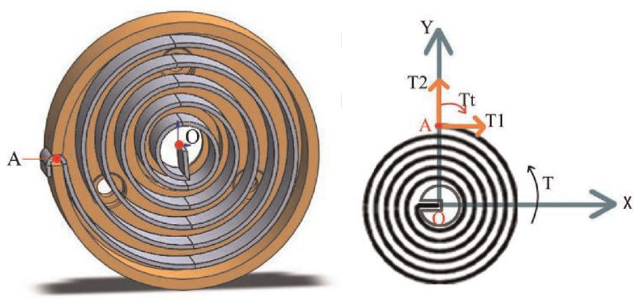
Installation structure and force of the spring.
During knee movement, springs 1 and 2 are driven by the calf and inelastic rope, respectively. Since the rotation of the knee joint will produce torque Ta and Tb, the torque produced by the double spring structure together is T. The resistance caused by friction is temporarily ignored, so T can be calculated as

Since the coil springs have the same rotation angle due to the motion of the knee joint, Ta and Tb can be defined as:


where, ø is the rotation angle, K is the coil spring stiffness coefficient. Thus, the torque of the coil spring during motion is calculated as

In addition, according to the maximum theoretical torque formula shown in Formula (5) below, under the condition that the size of torque required by formula (2) and (3) can be obtained, existing suitable coil-springs can be selected to match with different width and thickness specifications in the market for further design.

Where, σb is the tensile strength and Zp is the shaping sectional coefficient,

Where, b and h are the width and thickness of the coil spring. So, the maximum theoretical torque can be expressed as,

Structural design of the exoskeleton device
The coil spring is installed in the coil spring box, as shown in Figure 5. Torque T is generated when the shaft is rotated 60° due to the set pretension, so point a fixed with the helical spring barrel slot is affected by torque Tt, tangential force T1, and radial force T2. In addition, the driving load is generated by restoring the elastic deformation of the coil spring. Figure 5 shows the installation structure and force of the spring.
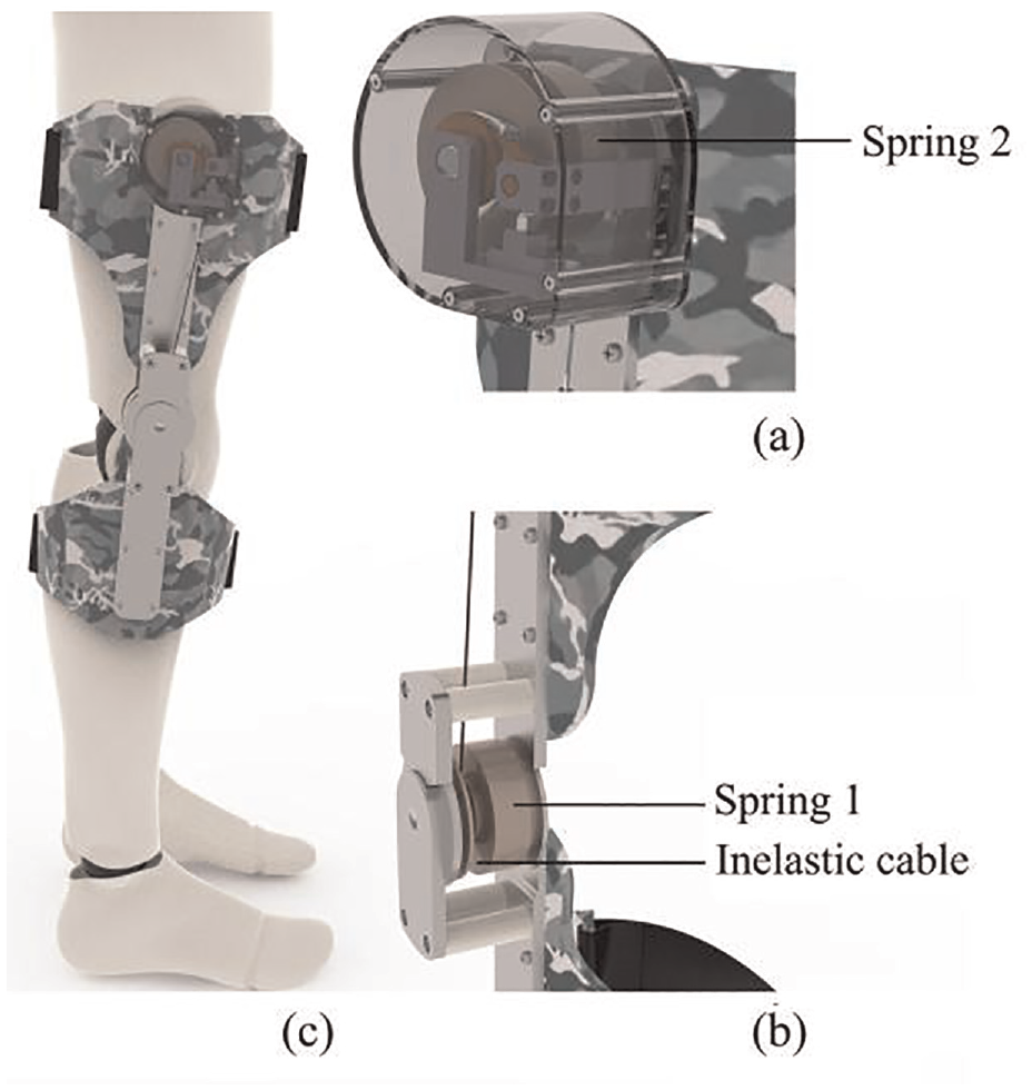
Figure 6 shows the structural details of the exoskeleton and the overall installation diagram, the knee exoskeleton has two main parts attached to the thigh and calf by connecting rods. Both parts are provided with a coil spring as an energy storage element. The spring 1 at the knee joint is driven by the movement of the lower leg, and the spring 2 at the thigh transmits the movement through a rotating ring with an inelastic rope.

Detail of exoskeleton structure and overall installation diagram: (a) the mounting structure at the thigh consists of: 1 spring box, 2 limiting element, 3 ratchet, 4 drive shaft, 5 rotating ring, 6 pawl, 7 inelastic rope, (b) the structure is installed at the knee joint, and (c) overall structure diagram.
The mounting structure, which is fixed to the thigh, includes a ratchet, a limiting element, and a drive shaft which can be fixed to the spring. In addition, a ratchet pawl is also provided, which can play a role in the normal process of human movement, so that the deformation and recovery of coil spring 2 can be adapted to the process of human movement, and help the process of human leg lifting. The two coil springs are connected by a rotating ring and an inelastic rope so that the motion of the knee joint can be further transmitted to the thigh. When the exoskeleton is working, the rotating ring is also provided with a top wire fastening screw to prevent the rope from sliding, and the rotating ring and the drive shaft are fixed to ensure that the movement is synchronized with the same frequency.
The installation part at the knee joint position mainly includes a rigid connecting rod, a transmission shaft, and a rotating ring, and the matching is completed by the chimeric connection combination of the thigh connecting rod and the calf connecting rod at the knee joint position. On this basis, the human body can be worn after connecting the wearing structure. Note that the drive shaft, rotary ring, and coil spring are set coaxial with the knee joint to ensure that the motion of the knee joint can be transmitted to the knee joint mounting portion of the exoskeleton.
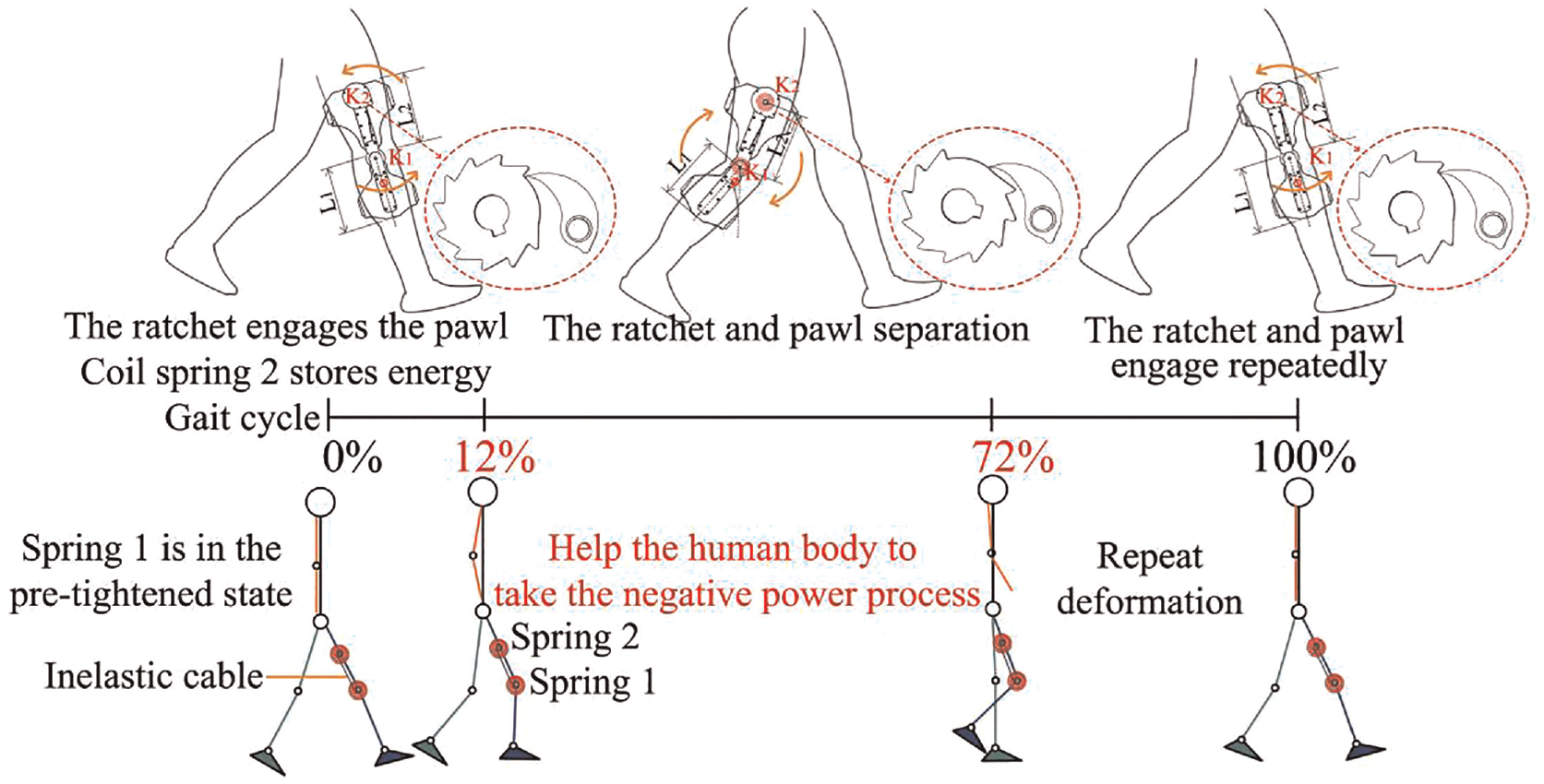
Take right leg as an example, the energy storage and release process of the spring power stage can be determined as follow. The spring 1 installed at the knee joint is driven by the calf in the process of natural walking of the human body. However, the spring 1 is limited by the preloading force at the initial stage, that is, when the calf rotates at any Angle, the device can be naturally restored to the initial preloading Angle. In this case, the exoskeleton can help the calf to do negative work and reduce the force applied by the human body to lift the leg. The spring 2 does not set the pre-loading force, and in the process of the spring 1 rotating with the calf, it generates deformation driven by the inelastic rope, and stores the energy at this stage. Similarly, in the process of leg lifting of the human body, the spring 2 restores the initial state, releases the energy to assist, and achieves the purpose of simultaneously assisting the two coil springs.
In this process, certain restrictions will inevitably occur due to the pre-load force set by the coil spring, which is explained in Figure 7. The advantage is that these limitations will not affect the movement posture of the human body.
Decomposition diagram of power assist stage.
In this study, the structure of double spring is selected, and the distribution position of the spring is shown in Figure 7. With the range of motion Angle of knee joint as the basis of adjustment, the initial state of the spring is pretension state. When the natural walking period of human body is 0%, the elastic deformation of the spring 1 reaches its peak. The spring 2 is driven by inelastic rope connection. At this time, the ratchet engages the pawl and Spring 2 stores energy. When reach about 72% of the gait cycle phase, two springs energy release process is over. During this period, the spring produces elasticity to help the human body in the negative working process, cooperate with the muscles to assist the leg lifting process, reduce the consumption of the human body, and complete the assist phase. Figure 8 shows the exoskeleton device worn on the human body.
The knee exoskeleton consists of two parts, the thigh mounting part and the knee joint mounting part, which are connected by a rigid structure: (a) detailed view of the thigh section, (b) detailed view of the knee joint installation section, and (c) schematic diagram of exoskeleton worn by human body.
In order to complete the help process, the exoskeleton device is initially set at 60° of knee flexion (pre-tension design). Furthermore, the ratchet also retains the number of 60° of teeth, and release the ratchet claw in the energy storage and release stage, in order to reduce the resistance caused by pretension, which may hinder the normal walking. Eventually, it helps the exoskeleton to release the energy when the muscles consume the metabolic energy for negative work, and to store the energy when the muscles use the metabolic energy to work actively. Therefore, the knee exoskeleton can partially replace the function of the lower limb muscles, reducing the metabolic cost consumed during walking.
Numerical simulation of the energy storage unit
Coil spring simulation
The stress process of coil spring was analyzed using the Ansys Workbench software. In the context of Ansys Workbench software environment, the force of the spring is analyzed by adding the required material properties, establishing coil spring model, increasing the load with fixed constraint, and applying the torque. The driving torque for different section sizes can effectively simulate and analyze the force situation of the spring, and reflect the stress and strain characteristics, as well as energy changes of spring with a more intuitive force cloud map. Finally, it provides reliable data support for subsequent design through data result processing and analysis.
Add material attributes
Table 3 shows the properties of the 65Mn spring steel, which is selected as the material of the coil spring and assigned in Ansys software during numerical analysis.
65Mn material properties.

Draw the model
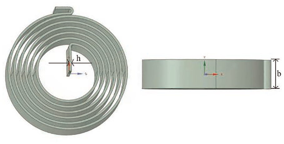
According to different coil spring sizes, a 3D model was Established and meshed to prepare for the subsequent FEM analysis, as shown in Figure 9.
Establish energy storage element model.
The size selection and performance calculation of helical spring can be carried out according to JB/T7366-1994 standard. Executive standard options range from 0.5 to 4 mm in thickness and 5–80 mm in width. Finally, the spring with thickness between 0.5 and 1.1 mm is selected for the test. At the same time, the width of each 5 mm is selected for a simulation, and then the appropriate spring is selected according to the simulation results.
Apply the load
In order to fit the actual drawing process and make the simulation calculation more accurate, a torque and its bearing surface were added to the inner edge of the model under fixed loading constraints, and then the supporting torque and deformation were output to obtain deformation laws of different section sizes.
The deformation angle is 60°, bearing torque in the process can be calculated as,

Effective energy storage level Up is calculated as follow,

Effective storage density Qp also can be defined as,

Therefore, according to the torque of 3.1415 N m, the simulation analysis of different spring section sizes is completed, and the appropriate coil spring is selected according to the section size of coil spring and the change law of torque and energy.
Post-processing and data analysis
According to the standard range of coil spring, the same conditions of torque and coil spring are analyzed, and the relationship between the change of stress and energy and the thickness and width of coil spring is analyzed. Figure 10 shows the comparison of the expected deformation efficiency of the spring.

Deformation efficiency diagram of 0.8 × 10 coil spring: (a) maximum shear elastic strain (m/m), (b) maximum shear stress (Pa), (c) total deformation (m), and (d) strain energy (J).
As shown in Figures 11 to 13, the spring deformation is directly related to its thickness and width. (1) When the width is determined and the thickness of helical spring is increased, the shear elastic strain, maximum shear force, total deformation, and strain energy parameters are reduced; (2) Determine the thickness, increase the width of the coil spring, the corresponding parameters will decrease; (3) The strain energy of coiling spring can meet the use requirements. In addition, the deformation efficiency is also reflected in Figures 13 to 15, where the helical spring widths are 5, 10, and 15 mm, respectively. The abscissa is the spring thickness, and the ordinate is shear elastic strain, maximum shear force, total deformation, strain energy, and other parameters.

Relationship between coil spring deformation and efficiency I.

Relationship between coil spring deformation and efficiency II.

Relationship between coil spring deformation and efficiency III.

Output torque curve of power assist device.

Diagram of exoskeleton and electromyography equipment worn by subjects.
Based on the numerical analysis results above, the equipment requirements, and human wearing demands (in the sagittal knee wear reasonable and comfortable), a coil spring with a thickness of 0.8 mm, 10 mm width, and a tight outer diameter of 50 mm shall be applied to the device.
According to the above numerical analysis results, the coil spring with a thickness of 0.8 mm, a width of 10 mm, and an outer diameter of 50 mm is adopted for equipment requirements and human wearing requirements (mainly reasonable and comfortable wearing on the sagittal knee joint).
Exoskeleton efficacy validation
Tension test
In this experiment, the torque generated by rotating the exoskeleton device at different angles can be obtained by using an analog force gauge to measure the force. The effective measuring range of the device is 0–50 N.
Before the test, the scale was zeroed, the fixture was installed on the end marked with pull on the tension meter, and the exoskeleton was connected to the fixture for test. After debugging, the tension meter is used to measure the tension of the whole mechanism, which is converted into the torque of the mechanism by calculation. At the same time, it is necessary to use the protractor to determine the Angle of the mechanism and ensure that the test is carried out in an increment of 10° during the experiment. When measuring, ensure that the tension meter and the booster mechanism keep vertical to ensure the accuracy of the measured value.
The output torque of the mechanism obtained by measurement is shown in the Table 4 below:
Output value of tension meter.

The curve shown in Figure 14 can be obtained from the obtained torque output:
It can be clearly seen from the figure that there is a certain error between the measured value and the calculated value, which is inevitable, but the torque trend can be consistent and the error is small. Especially when the rotation Angle is 60°, the measured torque value is 3.20 N m, and the calculated torque value is 3.14 N m, which verifies the effectiveness of the device to a certain extent.
Electromyography test
To further verify the effectiveness of the exoskeleton, more accurate human movement information can be obtained. 28 We tested and compared two sets of comparison experiments in a healthy male with or without the exoskeleton based on the Delay wireless surface electromyography test system.
A healthy adult male (175 cm tall and 62 kg in weight) was selected as the test subject. Before the test, the skin was first exfoliated and disinfected with alcohol. Secondly, the electrode block was fixed on the skin surface with electrode paste to prevent the influence of sliding on the electromyographic test during the test. Figure 15 shows the exoskeleton and EMG device worn by the subject. The tester completed several walks in the natural state, and recorded important data such as electromyographic signals, joint Angle, and joint torque during the walking process. Then, the analysis and calculation were carried out to evaluate the effectiveness of the improvement of exoskeleton strength.
Data processing and analysis
Multiple tests with and without an exoskeleton were performed on a subject to obtain knee torque variation data, which were then averaged for processing.
As shown in Figure 16, we can conclude that the human body has a significant tendency to reduce the knee joint moment during the whole gait cycle after wearing the exoskeleton device compared to not wearing the exoskeleton. Through numerical analysis and calculation, we found that the knee torque could be reduced by 10.1% at most, and the average knee torque before and after wearing the exoskeleton device was reduced by 18.1%. Therefore, the results of the experimental data show that the knee joint assisted exoskeleton can play a role in the negative work stage of the human body, which has a certain feasibility.
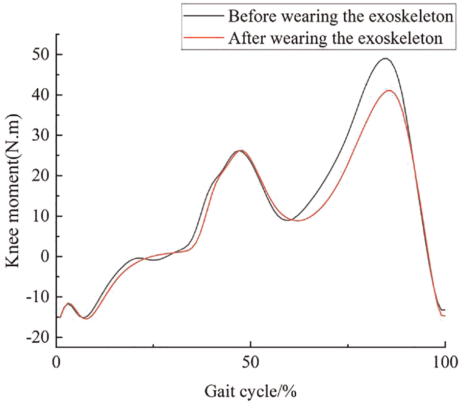
Knee joint torque change chart.
Since the EMG signal is periodic, the muscle signal obtained in the experiment is intercepted as the data in a single gait cycle for processing. The results after filtering by Visual 3D software are shown in Figures 17 to 22.

Electromyography of rectus femoris.

Electromyography of tibialis anterior.

Electromyography of semitendinosus.

Electromyography of peroneal longus muscle.

Electromyography of medial gastrocnemius.

Electromyography of lateral femoral muscle.
Since the exoskeleton is an additional external device worn on the human body, it is inevitable that the exoskeleton will cause a certain increase in muscle metabolism during the normal process of movement after the human body. At the same time, due to the internal mechanical structure and energy conversion, this part of the increased energy will be used to reduce the negative work phase of the human body, so as to achieve the purpose of assisting the human body. It should be emphasized that after wearing the exoskeleton, the EMG amplitudes of the semittendinus and peroneus longus were significantly reduced. The data were processed and calculated according to the root mean square (RMS) values of different muscles. Thus, the root mean square values of the semitendinosus and peroneus longus were 55.5% and 14.9%, respectively. From the above experimental results, it is obvious that the exoskeleton device can reduce the intensity of some muscle movements and achieve the effect of promotion. Finally, the basic parameters of the knee assisted exoskeleton design are shown below in Table 5.
Basic parameters of knee assisted exoskeleton design.

It needed to be highlighted that (1) due to limitations in experimental facilities, physiological indicators such as heart rate and metabolism were not evaluated. (2) The corresponding simulation results need to be further verified by processing a prototype through experiments. So, it will be considered seriously in our future research.
Conclusion
In this study, a knee exoskeleton device was designed and verified by experiments. From a large number of numerical and experimental results, it can be concluded that: (1) In the state of wearing exoskeleton, the storage of deformation efficiency of coil spring decreases with the increase of thickness and width. (2) The experimental results show that the maximum torque of the knee joint can be reduced by 10.1% and the average torque can be reduced by 18.1% after wearing the exoskeleton device. (3) The amplitude of EMG signals of some muscles also decreased significantly, which decreased by 55.5% and 14.9%, respectively. Therefore, exoskeletons can play an effective role during exercise.
It is important to note that an inelastic rope connected to an elastic energy storage element reduces the tension state during energy transfer. Therefore, the tension design should be carried out in the subsequent design process to reduce the loss during energy transmission and improve the performance of the exoskeleton.
Footnotes
Handling Editor: Chenhui Liang
Declaration of conflicting interests
The author(s) declared no potential conflicts of interest with respect to the research, authorship, and/or publication of this article.
Funding
The author(s) disclosed receipt of the following financial support for the research, authorship, and/or publication of this article: This work was supported by the Ministry of Education Youth Fund Project (Grant numbers 21XJC760003), the Outstanding Talents Support Program Project (Grant numbers 106-451420001), and the Common technology and field fund for equipment pre research (Grant numbers 106-418321001).