
Abstract
Distributed Energy Resources (DERs) play a significant role in reducing carbon emissions and improving the power system, nonetheless, maintaining the stability of the system parameters under faulty conditions is a major challenge. To minimize fault duration and maximize the system’s fault tolerance capability while maintaining affordability and being environment friendly, DERs supported by storage units are used in parallel with the main grid which offers promising results. This paper proposes the utilization of DERs as the primary source while the main grid shares the peak load. The paper also discusses the application of Phasor Measurement Units (PMUs) to record current and voltage values. PMUs are used to detect the fault in its early stage and communicate to the central controller to shift the load on storage units and isolate fault locations. The operation is controlled at two levels, that is at the load end and the junction point of the grid and DER. Any anomaly detected by PMUs is tested for the fault location, where faults are then controlled and minimized using the proposed method while keeping economic factors under consideration. The system is tested in light of results from mathematical modeling and design simulation which show very low latency time against demand response and quick isolation of fault location. A comparison with existing and previous works also shows the promising performance of the proposed fault-tolerant power system using PMUs.
Keywords
Introduction
Amidst the advancing technology and resources in the generation, the idea of energy saving and using alternative energy sources is becoming popular. Microgrids are in use in order to generate power at the distribution side using the available means hence emphasizing alternate resources. Microgrids are Low Voltage (LV) Networks consisting of Distribution Energy Resources (DER) that are basically micro-generation sources (MS). It is connected with loads and gets its primary supply from Medium Voltage. 1 DERs are generally considered as non-dispatchable energy resources with no constant active and reactive power. On one hand, they are considered environmentally friendly, however, a downside is unreliability in supplied power, for which they have to be utilized along with grid-connected MV. A detailed analysis of DERs is given by Singh et al. 2 focusing on design, benefits, and challenges. Featured DERs such as turbines, fuel cells, wind generators, and Photo-Voltaic (PV) panels are attached to the network electronically and controlled using Microsource Controllers (MC). The use of DER depends largely depend on geographical location and locally available resources. Power supplied by DER depends on its rating which ranges from a few kW to MW.
Microgrid mainly operates in two modes. One is the interconnected mode in which it operates in connection with the main grid. In this mode the main purpose of DER is to supply extra power needed at the distribution end, that is, peak load shaving. The DERs require a stable connection with the grid so they can work without altering grid dynamics. As the voltage and frequency keep changing as the demand changes at the distribution end, a small variation can have massive effects on the grid dynamics. Thus a droop control strategy is adopted in order to achieve the set value of voltage and frequency and minimize system harmonics. A droop control strategy involves sensors and actuators to measure deviation and a control system to overcome a deviation based on load and resource shifting. When connected in grid-tied mode, another important challenge is to overcome faults occurring within the microgrid such as a sudden disconnection of one of the DERs or fault in the transmission line. It is important to localize the fault before an action is performed for which many strategies have been proposed to provide an extensive Fault-Tolerant Control (FTC) system 3 which can be either Active FTC or Passive FTC as explained by Basak et al. 4 Phasor Measurement Units (PMUs) are used to sense and record current and voltage values and anomalies are examined for fault locations, but can also increase system cost drastically. Thus, the need for an economic and faster fault control system is impertinent in DER-based power networks. After fault localization, load optimization is performed in four steps which are based on demand response: (1) Load shedding, (2) Load prioritizing, (3) Load scheduling, and (4) Load shifting.
The second mode of operation is islanded mode in which a microgrid is isolated from the main grid because of some fault occurance at the grid end or in some cases, planned disconnection. In an this scenario, only DERs supply power to the connected load. However sudden disconnection can cause a fault within the microgrid leading to power interruption. In an islanded mode, the load is gradually shifted to DGs to slowly step up to system parameters. A sudden surge, otherwise, can cause severe damage to system equipment and release harmonics. DERs play a significant role in reducing carbon emissions and improving the power system, nonetheless, maintaining the stability of the system parameters under faulty conditions is a major challenge.
This paper focuses on overcoming two types of faults. One is caused as a result of microgrid disconnection from the main grid and the other fault occurs with a microgrid either due to disconnection of any DER or fault in the distribution line. The contributions of the research are as follows:
• A fault-tolerant control model is proposed in order to improve fault tolerance in the system
• Fault duration is minimized, and the system’s fault tolerance ability is maximized while keeping it affordable and environment friendly
• The use of PMUs is discussed for recording current and voltage values hence detecting the faults in the system
These contributions are made by proposing a model in which multiple DERs are operated in parallel in grid-connected mode and a hierarchical control is used in the system. This paper also proposes the utilization of DERs as the primary source while the main grid shares the peak load. PMUs are used to detect the fault in its early stage and communicate to the central controller to shift the load on storage units and isolate fault locations. DERs are supported by storage units that can either be batteries or fuel cells. Under normal operation, DERs continue to supply power to their designated load. If any of the two faults occur, the load is shifted to the storage unit before it is shifted to another DER. In the hierarchy, the main controller is the microgrid control center (MGCC) while in the second order, load controls (LC) and MC are installed. The control strategies are discussed in Etemadi et al. 5 DERs supported by storage units are used in parallel with the main grid which is affordable and offer promising results. The system is tested in light of results from mathematical modeling and design simulation which show very low latency time against demand response and quick isolation of fault location. A comparison with existing works also demonstrates the superior performance of the proposed fault-tolerant power system using PMUs.
The organization of the paper is as follows: the literature review is described in Section 2; the research methodology is mentioned in Section 3. Simulation is presented in Section 4. Section 5 reports the results and discussions. Finally, the conclusion with future recommendations is presented in the last section.
Literature review
Distributed generation
Distributed Energy Resources include both Distributed Generation (DG) technology and energy storage technology. Distributed generation. According to Jiayi et al., 6 DG is a low-capacity power supply directly attached to the distribution end where it is consumed by the user. DG is further divided into two categories (1) Conventional generation and (2) Non-conventional generation. Most DG are non-conventional renewable energy resources which include generation by PV, Microturbines (MTs), Wind turbines (WTs), Biomass, and geothermal energy. They offer multiple advantages of higher energy efficiency, lesser environmental hazards, and utilization of lesser space and resources for installation. However, one of the main challenges of DERs in the integration of multiple resources is uncertainty in electricity production. As the sources are mostly natural and variable, they can cause variation in electricity generation from DERs, for example, Wind power can vary from atmospheric changes, MT relies on hydro reserves, and power from PV is proportional to the amount of solar energy stored. This uncertainty can lead to severe problems in a distribution network such as disturbance in demand-supply relationship balance, changing dynamics of the transmission network, and causing reverse power flow. In Reiter, 7 standard specifications for interconnection and interoperability of DERs with the main network are presented. It provides details on safety, testing, performance, operation, and maintenance for connection. The large-scale incorporation of DERs in distribution networks is presented by Huda and Živanović 8
Inverters
Inverters are used to convert direct current (DC) from a DC source to alternating current (AC) such as from batteries to load. Almost all renewable distributed generators produce DC output thus inverters are an integral part of the smart grid. In a microgrid, output from inverters is not directly provided to load. It is regulated by controllers. Rokrok et al. 9 present an analysis of connected inverter control. For multiple distributed energy resources connected to the same load, active and reactive values are set to provide a consistent power supply. A voltage modulated direct control strategy for AC to DC converters is presented. 10 The proposed strategy defines the relationship between power control and voltage-oriented control methods. It is impertinent to mention that for fault localization and control strategy, current and voltage values provided by sensors should be accurate. Current transformers and potential transformers or PMUs record current and voltage values using sensors. This information is processed through the data acquisition unit before being forwarded to controllers for required action. The set values of active and reactive power and their control relies on the current and voltage values of the system and any deviation can cause a change in the reference values of the system.
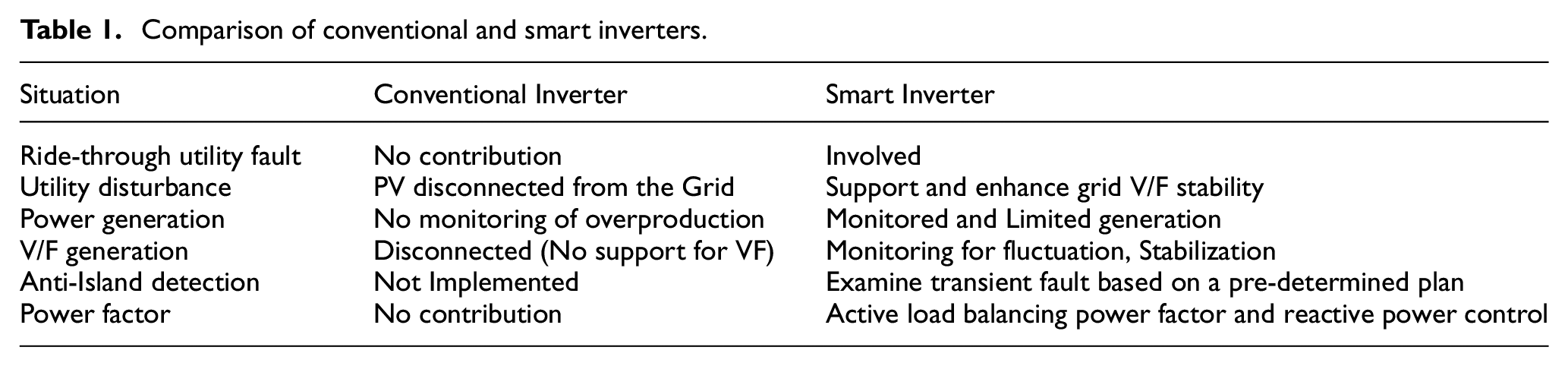
As current, voltage, and frequency make state variables for any system and act as primary data for any system calculation, it is important to get an error-free calculation of these variables. Research has been done on the accurate measurement of current and voltage values as provided in the literature.11–13 The control of inverters is managed using the switches. Fault in the switches can be dealt with using redundancy for an H-bridge inverter. 14 Delghavi and Yazdani 15 and Rahman and Oo 16 have defined control strategies to ensure power electronic interfaces are fault-free while maintaining quality at the same time. Table 1 compares various features of conventional and smart inverters.
Comparison of conventional and smart inverters.
Storage units
According to energy storage forms, storage units can be chemical battery storage, flywheel energy storage, and superconducting energy storage. Generally, battery storage included two components, an energy storage unit and a power conditioning system which is used to exchange power energy with a microgrid. The stored energy in the battery is dependent on its storage capacity, and it should be ensured that stored energy at any period is within its limitations. Suryanarayanan et al. 17 explain the battery sizing calculation required before installing them in any system. Storage unit constraints as stated in Suryanarayanan et al. 17 can be presented as the following equation:
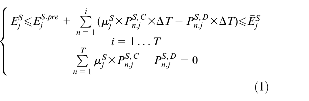
Where
Fault localization
Fault location in the network is widely discussed in the literature. Detailed analysis and review of different sensors are presented, with a discussion of faults occurring in them in order to improve efficiency. 18 Amin and Hasan 19 have presented a review on fault-tolerant control systems with respect to the advancements made in the technologies. The fault location method for short circuit analysis using the PMU is explained by Hong et al. 20 The paper is based on testing fault localization based on two PMUs installed at the main and lateral feeder. Conventionally, in literature, the fault locations are measured using PMUs, which are installed on the substations as shown in Figure 1. 20 The blue circles indicate the PMUs and the red one indicates the fault location. Several PMUs are installed in the system which measure the positive sequences in variations of current and voltage, in both the forward and backward direction, using the following equation:


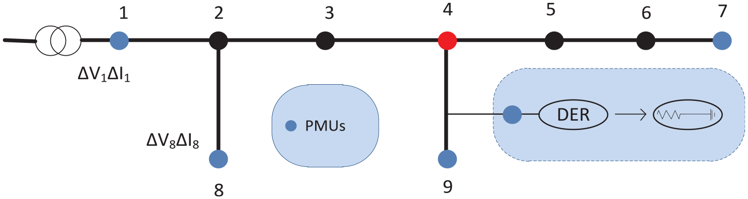
PMU-based fault detection.
Although the method discusses fault location identification in detail, on the contrary, it lacks scalability and is not efficient when implemented on large scales. Hong et al. 20 have proposed a similar strategy using 2 PMUs as represented in Figure 2. The method includes the lateral feeders of the system also. It proposes a two-stage method that calculates the fault location using PMUs for the main feeder, also incorporating the Remote Terminal Units (RTUs). Then short circuit analysis is used for analyzing faults at the lateral feeder and estimating the fault location.
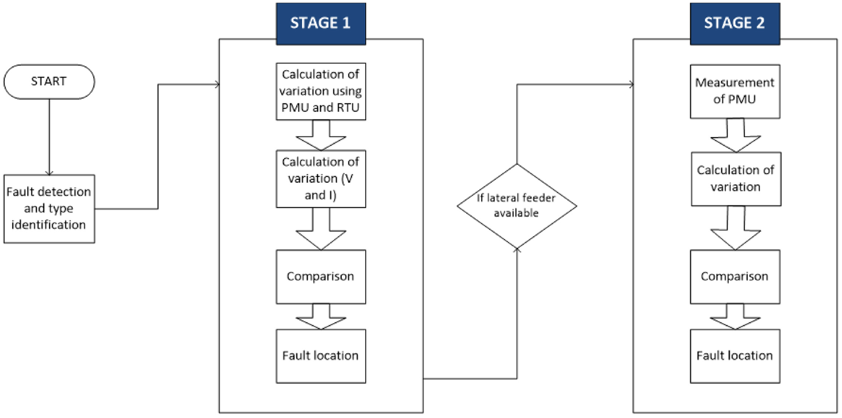
2-stage method for fault detection.
The current variation in lateral DERs was calculated as:
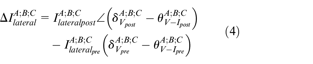
Where
In the case of large-capacity DERs, the current was calculated as:
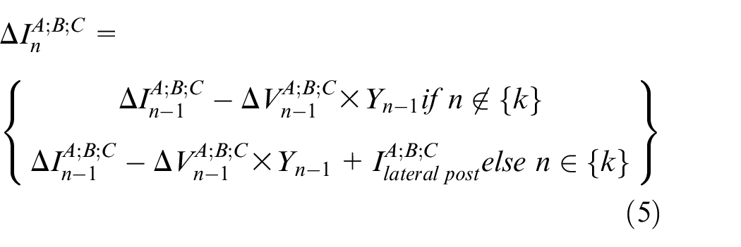
The current variation is expressed as positive, negative, and zero sequences:
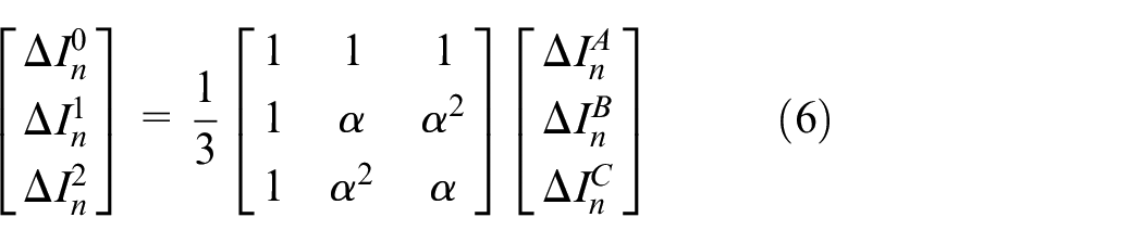
Where
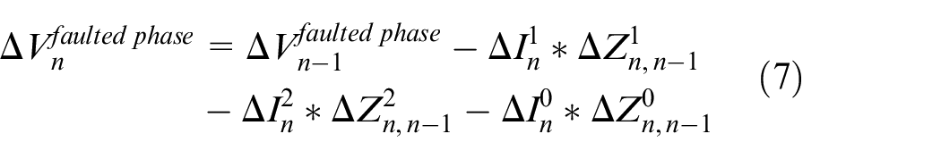
Similarly, voltage variation for the faulted phase:
To show the verification of the proposed technique, a test case study was discussed. 20 As mentioned in the above-proposed method, two PMUs were installed at two points in the power system (Figure 3). Large capacity DERs were also included in the form of lateral feeders. For simulation purposes, virtual buses denoted as “Lat” were added at the connection points of the lateral feeders as shown in Figure 3. These were used to calculate the location of the fault on the main feeder. To measure the voltage and current from lateral feeders, RTUs were also placed in the network. Positive, negative, and zero sequence components were applied per kilometer, along the length of the line. The estimation of results showed an accuracy of 100% with low resistance (20 Ω) The accuracy decreased to 97.6% with the increase in resistance.
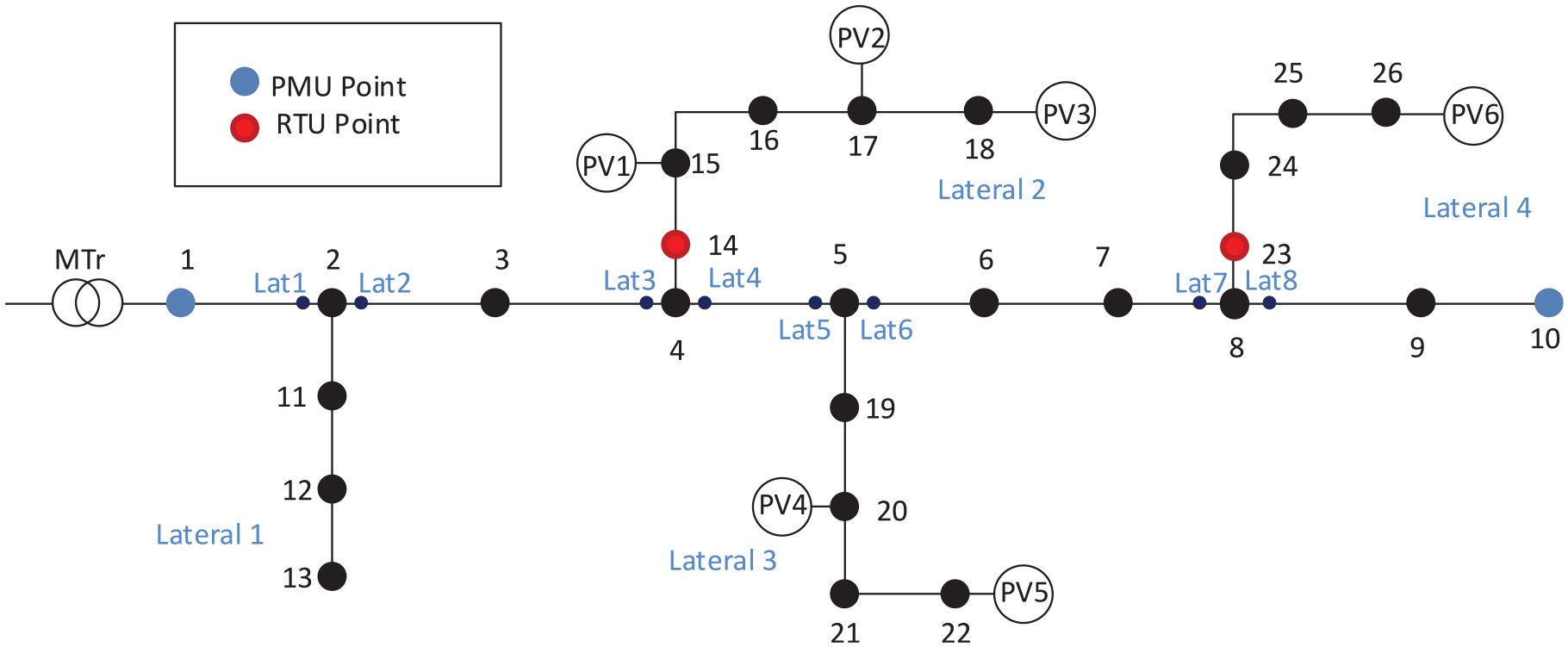
Test system for case study.
Mouco and Abur 21 present a technique that enables locating faults in a system, using Prony analysis to predict post-fault steady-state voltages. It uses PMUs to determine the voltages. LASSO algorithm, Sparse estimation, and Prony analysis-based digital filters are used to estimate fault locations, based on the circuit in Figure 4 and the flowchart of the proposed method is given in Figure 5.
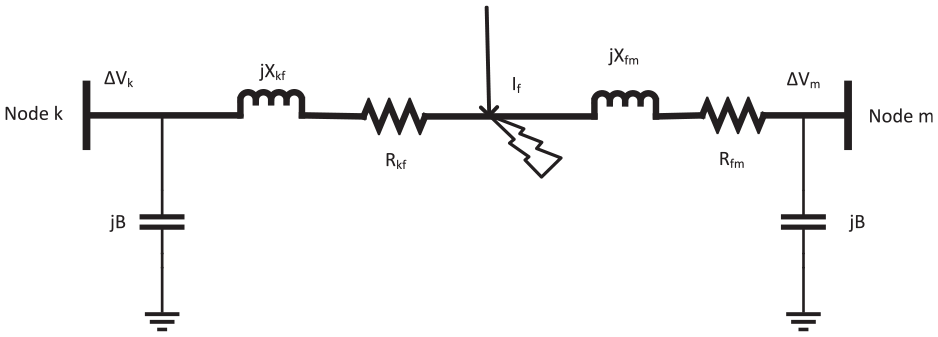
Fault in a transmission line.
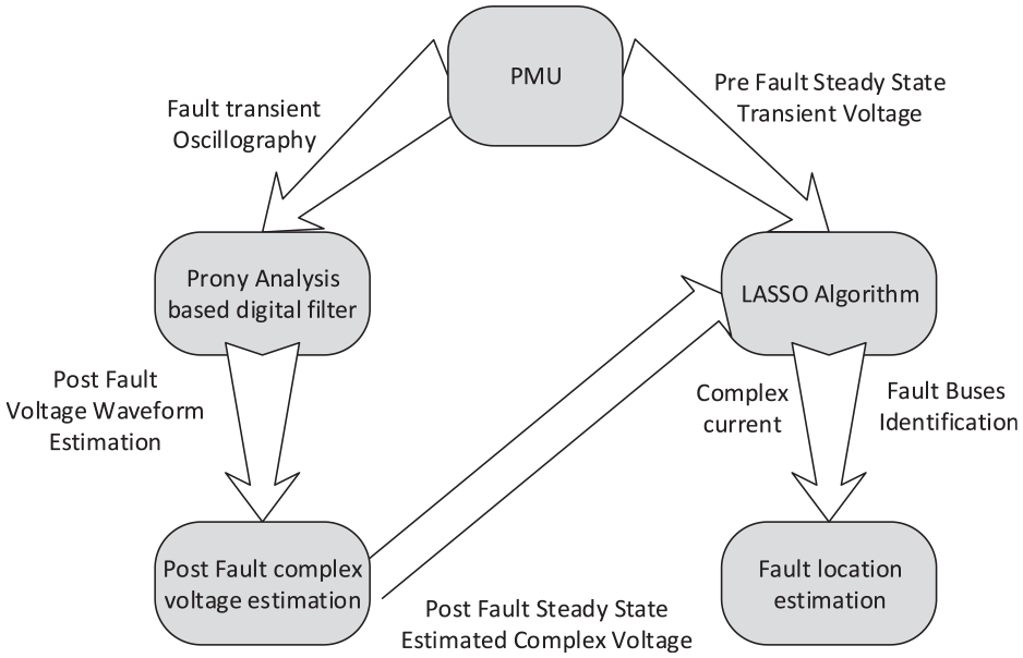
Sparse estimation.
Sparse estimation was used to find ΔI. Pre-fault steady-state values were obtained using PMUs. To determine the post-fault steady-state values, Prony analysis was used. The analysis extracts valuable information from the sampled system and approximates the nonlinear complex function to a sequence of linear combinations. PMUs can provide synchronized phase values for current and voltages thus the method is suitable for this application. The before and after fault steady-state voltage values were then input into LASSO Algorithm and fault location was estimated. The accuracy of the proposed technique was up to 99% with errors of less than 1%.
A detailed analysis of the control of VSC-based DER units is presented by Olivares et al. 22 Main control principles, model predictive control, drop control, and multi-agent control are mentioned.
Fault rectification
Although research has been made in areas of fault rectification there is very limited literature on fault repairing techniques based on the consolidated system. A sequence current-based protection approach is presented by Muda and Jena 23 in which three cycles of currents are recorded and mid-point faults are simulated to determine fault current. An approach called “Modified Triple Modular Redundancy (MTMR)” is proposed to deal with multiple faults occurring at the same time and manage them by introducing redundancy. 24 The development of an approach for a model-based fault accommodation framework is described by Allen and El-Farra 25 The technique is applied to sample data of distributed energy resources subject to control actuator fault. On the same principle, Zhang et al. 26 and Bellizio et al. 27 presented state-of-art accurate and efficient modeling of DER uncertainty calls for a comprehensive improvement. These also discuss machine learning and artificial intelligence technology to be incorporated for purpose of fault accommodation. Since the concept of smart and microgrid focuses on data monitoring and control digitally, novel techniques offer promising results for fault accommodation. In order to reduce the expenses of production loss, Artificial Neural Networks (ANN) are used to isolate and detect the faults in engines. 28 A decentralized optimal power flow system is explained for the distribution network. 29 Fault control using hardware redundancies is presented by Amin and Mahmood-ul-Hasan 30
An innovative passive-based intelligent method for anti-islanding is proposed that is a subsequent collection of intelligence-based models called gradient boosting. 31 To control fault using observer-based models and create fault isolation units in case of fault occurrence, an active FTC is proposed based on fuel actuators in the fuel supply line. 32 A commonly used one-class classifier, for fault detection in the distribution systems, is proposed by Lin et al., 33 which is based on small data available on fault conditions, and on the Support Vector Data Description (SVDD) method, that only requires the normal data for its training process. Incremental learning is added into the proposed framework to adjust variations of the incorporation level of DERs in distribution systems over time. Adequate literature is available on accurate measurement and monitoring of electric parameters of voltage, current, and frequency. Similarly, multiple strategies have been proposed for fault detection and localization in power systems. Since Microgrids are recently emphasized technology, and Distributed Energy Resources are becoming more popular, most of the research is focused on the successful implementation of technology with minimum disturbance. Research on fault detection and accurate monitoring can identify the problem, however, there is a need for a designed control system that can operate in response to faults and enhance the system’s fault tolerance and the literature does not provide much evidence of research on this area. Thus based on techniques and methods proposed by researchers in the relevant literature, this paper focuses on formulating a system to improve fault tolerance for DER-based networks. To deal with non-linear abnormalities in systems, a review of Sliding Mode Control is discussed in detail, along with the discussion about the implementation of the technology. 34
Most of the literature work is based on the principle of DER optimal scheduling for enhanced reliability of the system. This technique intelligently schedules the available DERs for optimal utilization. The load is distributed among DERs in order to achieve stability and avoid load shedding. Usually, it involves prior load forecasting and DER maximum load capacity calculations before transferring load to DER. This technique involves smart programing and a fast-switching system to work however, this technique does not ensure that DERs will be able to take up the full load in case of any disconnection from the main grid. Also, this may result in total system collapse if planning is not done properly.
In this paper, our contribution is mainly focused on proposing a fault-tolerant system for DERs mainly PV, MT, Solid Oxide Fuel Cells (SOFC), and batteries as storage devices. The proposed fault control system will be for the distribution network and the power network will be Microgrid connected to MV and a two-step hierarchal control system (1) MGCC, (2) MC and LC. MGCC will act as director of operations and control. In islanded mode, LC and MC will take charge based on either single operation mode or multiple operation modes. Proposed FTC will take into consideration multiple fault conditions (1) Operation in islanded mode, (2) Discontinuity of power supplied from any or multiple DERs, (3) Overcoming the impact of change in grid dynamics, (4) Overcoming reverse power flow faults. DERs play a significant role in reducing carbon emissions and improving the power system, nonetheless, maintaining the stability of the system parameters under faulty conditions is a major challenge. PMUs are used to detect the fault in its early stage and communicate to the central controller to shift the load on storage units and isolate fault locations. The operation is controlled at two levels, that is at the load end and the junction point of the grid and DER. Any abnormality recorded by PMUs is checked for fault location, where faults are then controlled and minimized using the proposed method while keeping economic factors under consideration. The system is tested in light of results from mathematical modeling and design simulation which show very low latency time against demand response and quick isolation of fault location. A comparison with existing works also demonstrates the superior performance of the proposed fault-tolerant power system using PMUs.
Research methodology
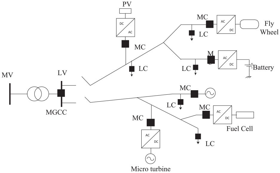
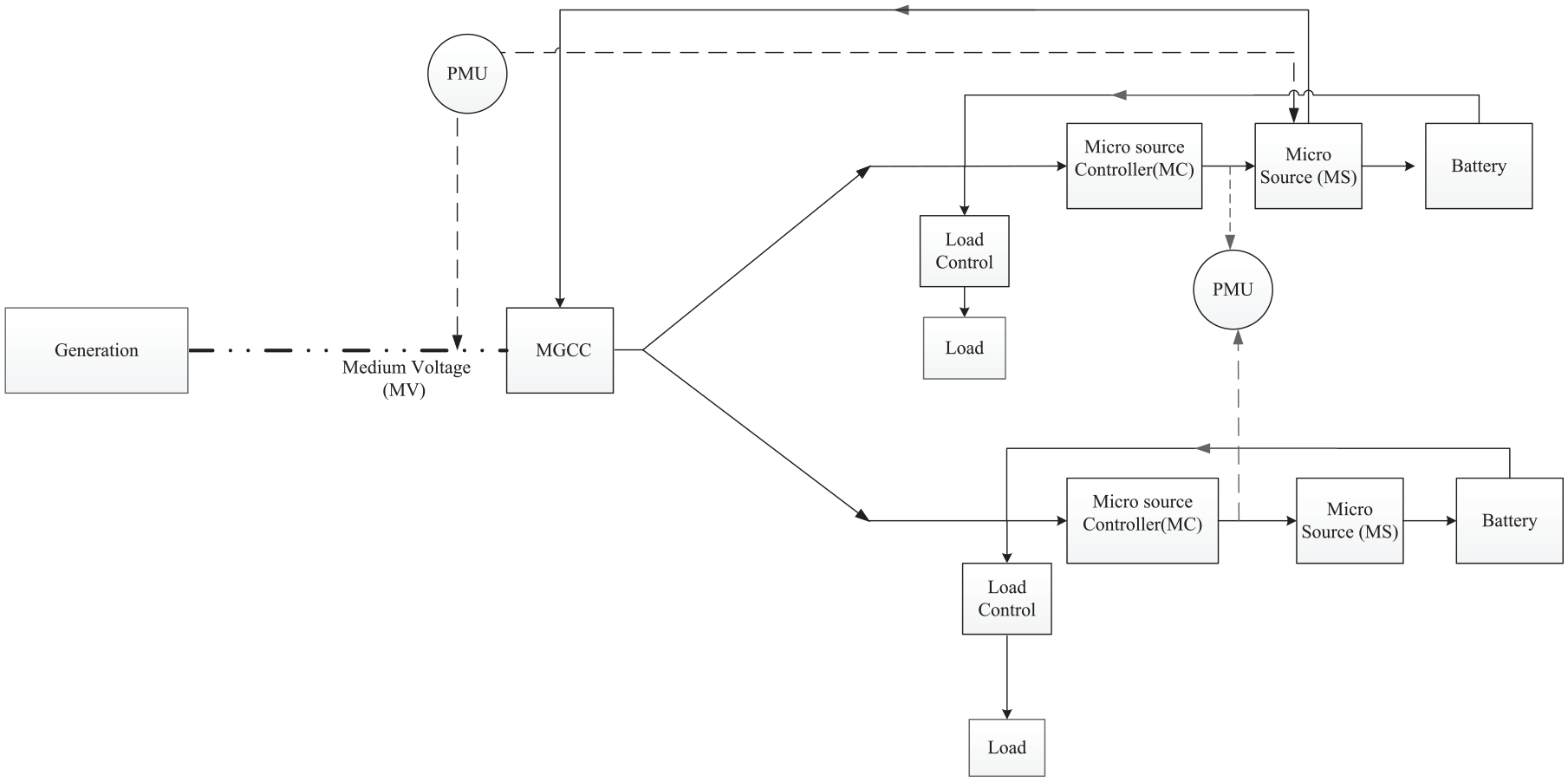
The methodology that is proposed in this paper can be used as a primary source as well as a secondary source for the distributed sources. MGCC, MC, and LC act as control points in the network as shown in Figure 6. Information from the main grid is passed on by MGCC to the network entities. It controls and commands according to monitored data (Figure 7). In the absence or disconnection of MGCC, the control is shifted to the MC and LC, according to some control strategies. 27
Control layout of system.
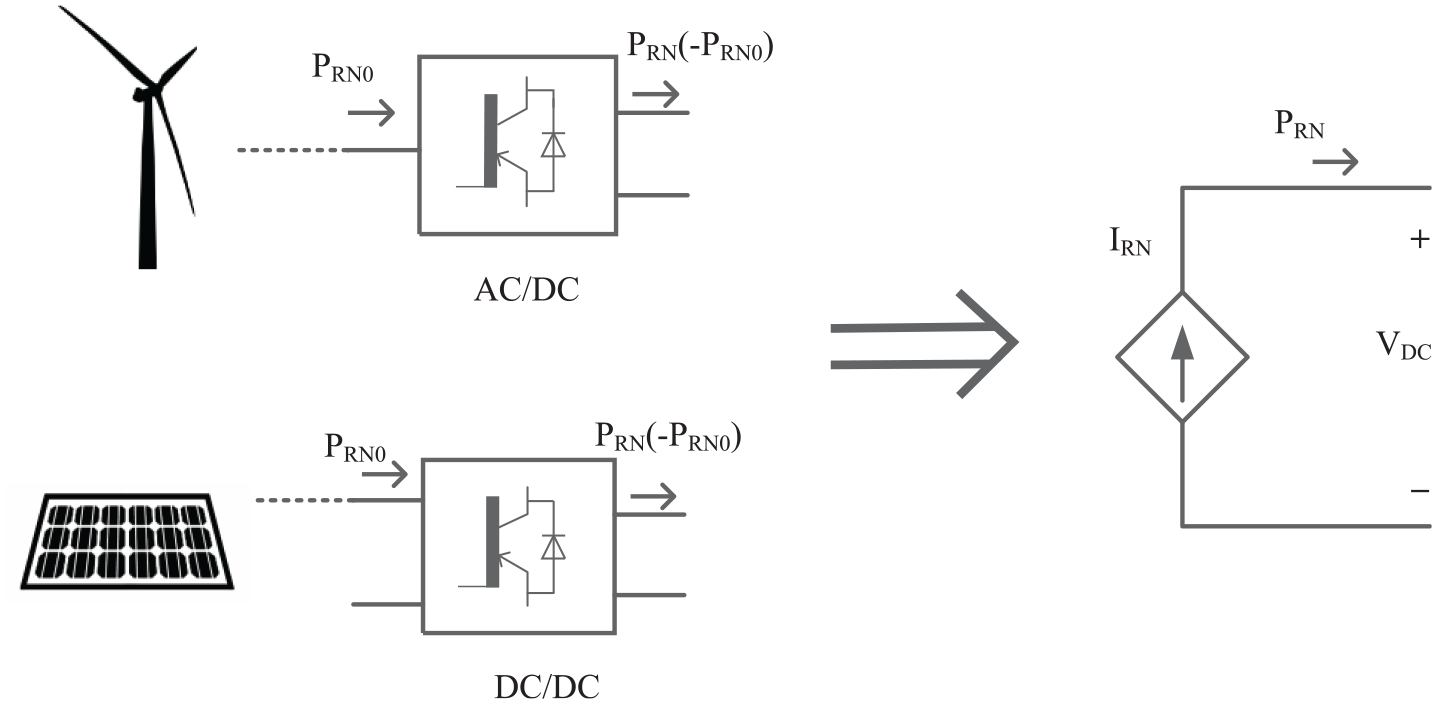
DER power conversion and transmission to system.
Fault occurrence and localization using Phasor Measurement Units
The proposed model is shown in Figure 8 in which multiple DERs are operated in parallel and in grid-connected mode. The model proposes the monitoring of both faults using PMU. PMU will be installed at MV and MS to notify any fault. PMU installed at MV will communicate with MGCC and MC. Similarly, PMUs installed with MC will communicate with MGCC and LC. It is important to mention that the proposed model does not provide information on fault allocation rather it improves fault tolerance in the system. In this model, batteries are installed at the load end with micro sources and in connection with MS and MGCC. These batteries get charged first before MC supplies any power to load. Once the batteries are fully charged, they get disconnected from MC and act as a reserve supply. Micro sources can then supply power to load at the distributed end either as a primary source or secondary source
Fault control method.
The faults in the DER can occur at the following points:
At the transmission line, main grid, or main generation at any point on high voltage transmission to low voltage distribution network, consequently isolating the DER from the main grid and making micro sources (MS) take control of the system.
In one of the micro sources either due to the interfacing of multiple MCs or a change in dynamics of one of MC causing an impact on MV dynamics. In this condition, MGCC will take some time to reach stability during which supply to the consumer will be interrupted.
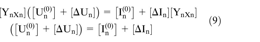
The microgrid has a multi-terminal transmission line with n terminals. With the optimal placement of PMUs at a strategic location, values of current and voltage can be measured in the matter for microseconds under steady-state and fault conditions. During steady-state, node admittance can be presented as:

where,
The admittance matrix is a sparse matrix, it has a greater number of zero elements as compared to the impedance matrix. This helps in saving storage memory while performing computations hence it is used instead of an impedance matrix.
Once a fault occurs between nodes of faulted line, the line current is measured using PMU. This line current forms node injection current at two terminals of faulted line.
Fault on the bus (from the main grid)
The admittance of line will be:
where,
Fault on the line (in MG)
If a fault occurs on the line between points i and j, the pre-fault admittance matrix will be:
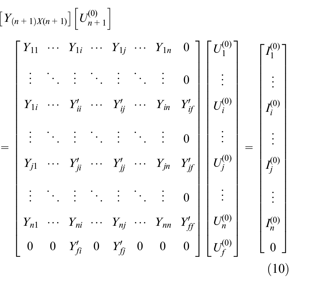
Where,
Node admittance matrix under fault condition becomes:
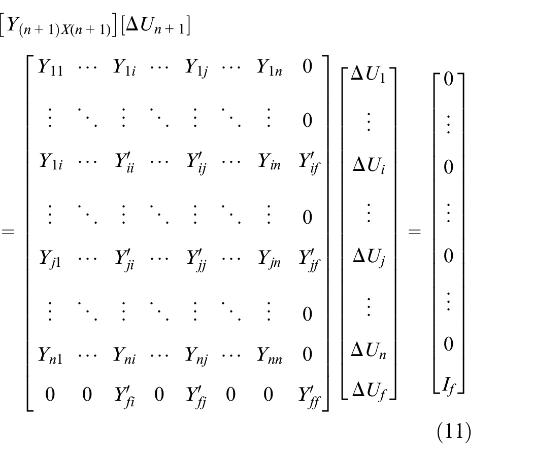
fth line represents
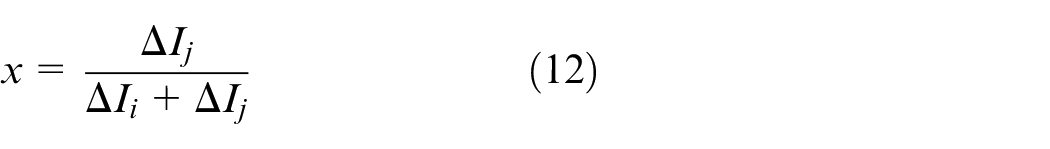
The value of x reaches from 0 to 1. The value of fault current will be the sum of both node injection currents at bus i and Bus j. To determine the type of fault current, positive, negative, and zero sequence values are noted.
Fault rectification
Fault 1
If fault 1 occurs monitored by PMU at MV, it will communicate fault information with MGCC and MC simultaneously. MGCC will disconnect itself from the microgrid and hand over control to MC and LC. Batteries will get operated and start supplying backup power to load instantly. Meanwhile, MC will start shifting load to micro sources and once the system is fully shifted to micro sources, it can disconnect batteries from the system again. If MC detects any abnormality, it can maintain supplying power to load or part of load through batteries. Once the fault is rectified, the system can gradually be shifted to the main grid. The process is shown in Figure 9.
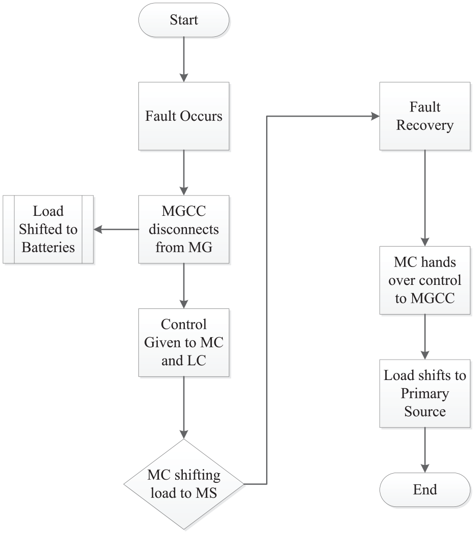
Fault control of fault 1.
Fault 2
If fault 2 occurs monitored by PMU connected with MS, it communicated the information to MGCC. MGCC disconnects MS from the system and shifts the system on batteries to achieve system stability. Once system dynamics get back to normal, the load can be shifted either on the main grid to the micro source based on the monitoring and control network. The working process is represented in Figure 10:
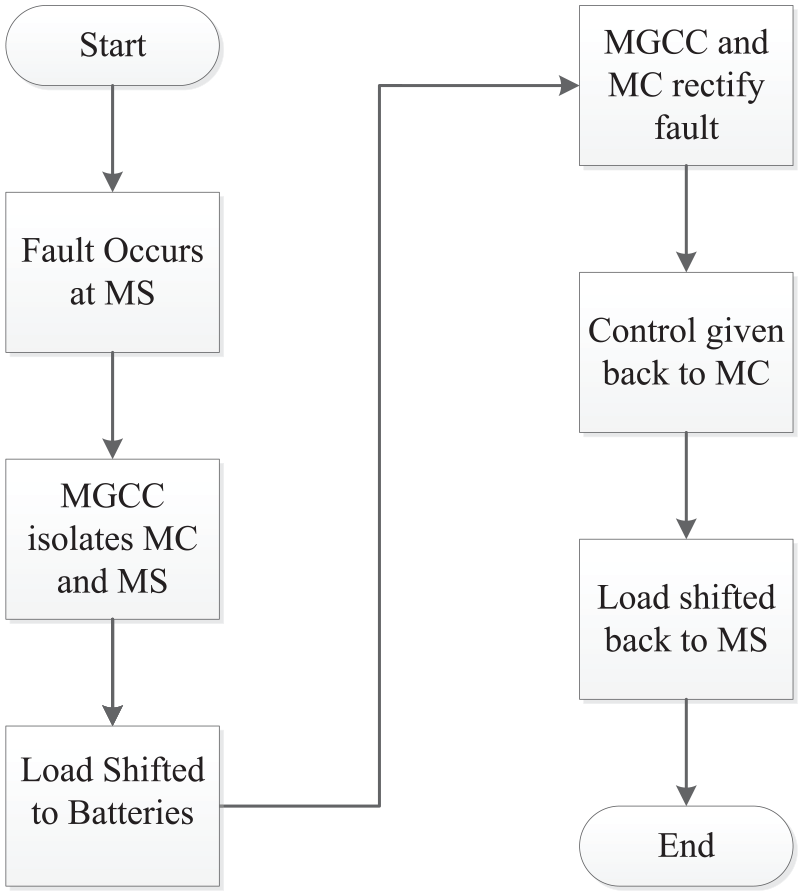
Fault control of fault 2.
Load shifting and storage units
The electricity consumption of load must remain the same even if load shape changes before and after load shift. It is also assumed that the power factor during load shift remains the same. The active and reactive power of storage units varies depending on the type of device used for energy storage.
Constraints of active and reactive power are presented as:
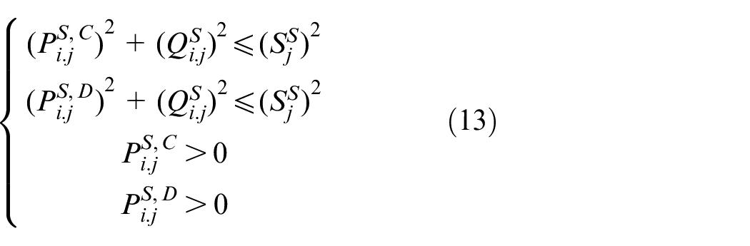
Where,
The battery lifetime highly depends on the number of transitions charge/discharge performed in a day. For simulation purposes, one transition for optimal operation is assumed.
The output range of both DERs, that is photovoltaic cells and wind turbine depends on the availability of available resources and the power prediction. For DG, the most important operating factors are the relation between active reactive power output and the generation range. Power electronics equipment links a DG to the distributed system. The flowchart in Figure 11 shows the mechanism to find fault locations when multiple buses operate in parallel.
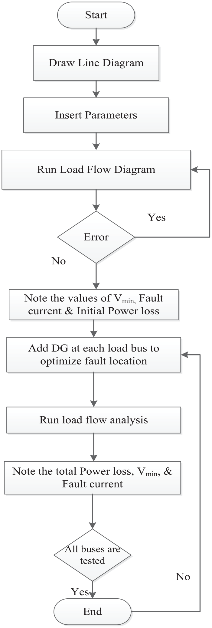
Fault location flow chart.
This mechanism can be duplicated for multiple buses. Based on this mechanism, sensors and control devices are designed.
In this work, it is assumed that there are only two faults in DER based network. However, fault can occur in the controller, inverter, or batteries. It is also assumed that batteries will be able to cater to load fully for a certain period and supply power to load without any voltage or current fluctuation when the load is transferred from the system to batteries. However, to maintain an uninterrupted supply to load for a certain period, huge batteries with potential storage capacity will be required. The medium voltage will act as the second supply voltage and DER is used as the primary supply voltage.
There are certain limitations and areas for future research in this paper. The first limitation is that to supply an interrupted supply, the system needs to install large batteries which will add initial cost to the system. It will also add to the maintenance cost of the system since batteries require continuous health monitoring. The other limitation of this project is that it requires individual load controllers and micro source controllers to be connected with MGCC. All load controllers need to be connected to individual loads for controlling inductive and ohmic loads. This is important as the inductive load will be shed first to achieve stability. However, it will require extensive control and communication network which will be complex in functionality.
Simulation
The simulation in Figure 12, is implemented for one consumer and two prosumers. Distributed Generation model is considered a microgrid. The consumer can take electricity from the DG as well as the main grid. The model is realized in Simulink, MATLAB. Simulation of two DGs was obtained, the former consisting of a 300 W PV panel and the latter, a 3-kW wind turbine. The power supply grid is 0.4 kV which is converted from 20 kV through a transformer.
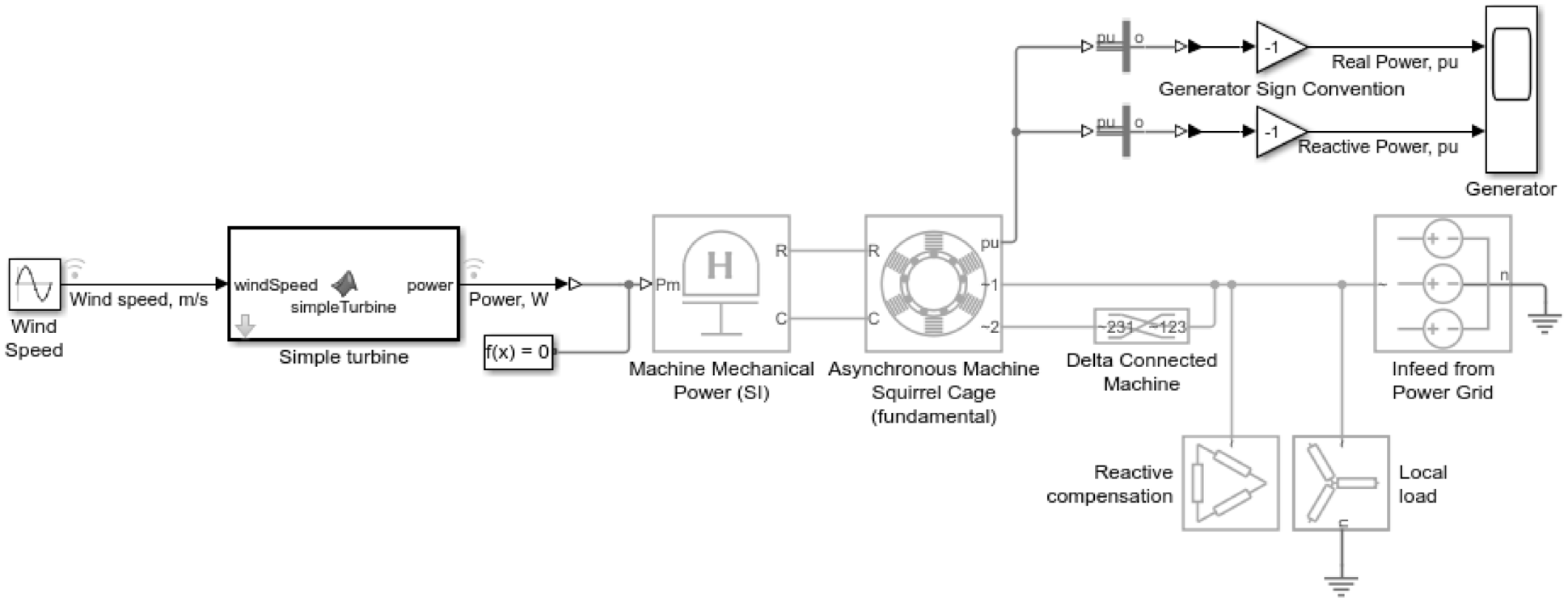
Wind turbine generation model.
The design above is of islanded WT connected with load at the distributed end. Since WT produces active power only, the system is compensated for reactive power. The main grid operating in parallel to WT is used as a secondary source for peak load shaving.
For Photovoltaic cells, the following model in Figure 13 in islanded mode was used.
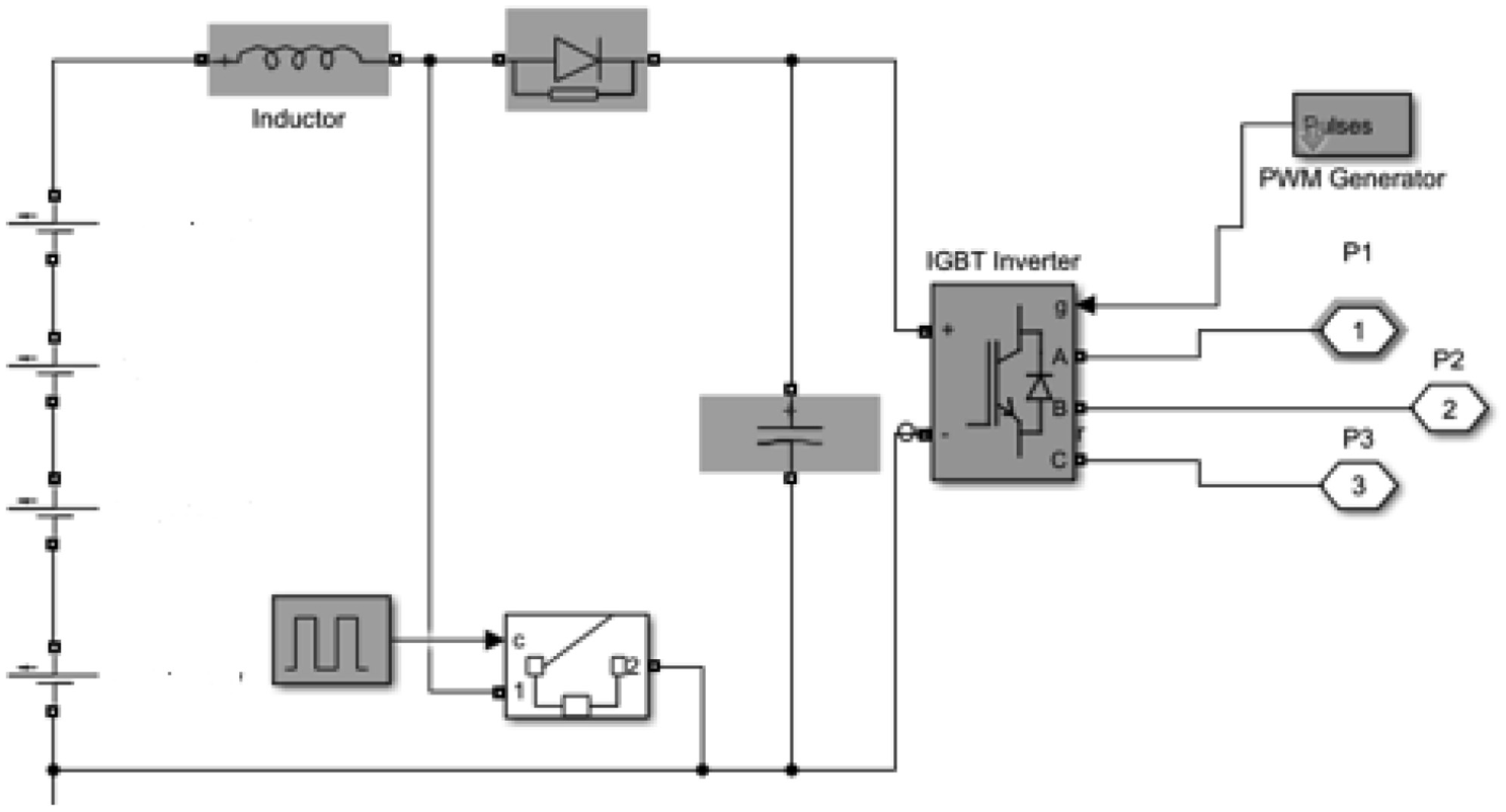
Isolated photovoltaic (PV) model.
The design uses 100 PV cells in series with an output current of 7A and a series resistance of 0.2 Ω. The design generates a DC output which is utilized to charge batteries initially and later to supply power to the distribution end load. Figure 14 shows the Microgrid simulation model.
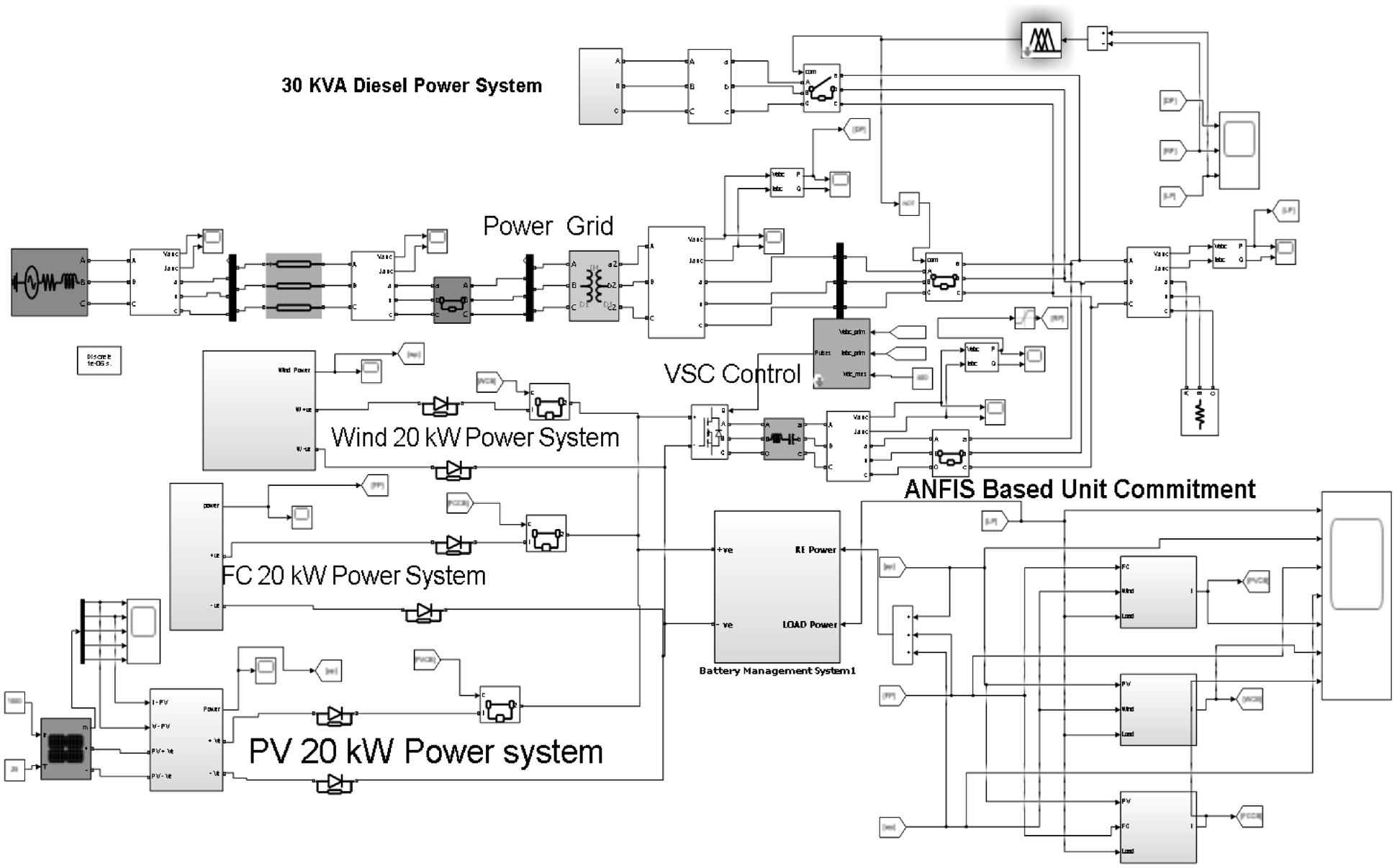
DER-supported Microgrid simulation model.
Simulation is based on distributed generation of the wind turbine, storage units, and photovoltaic cells. The design depicts the working of the grid in islanded and grid-connected mode. It included standard IEEE feeder parameters and various generation sources with pre-defined active and reactive power. IEEE 123 nodal analysis checks the complexities at the distribution end similar to the distribution feeder and the load holding capacity of the feeder. The standard IEEE 123-node feeder is shown in Figure 15 with an installed PV system and load nodes. The data set has been established with residential loads to construct node load profiles. The resiliency of the system can thus be checked through this nodal analysis. The data is tested for the first time for integrated generation resources and smart grid analysis. However, as the research work is more focused on fault diagnosis, we only focused on general evaluation through nodal analysis. The self-recovery process of nodes will involve the utilization of batteries to stabilize the system dynamics for a short period and disconnecting the affected nodes if required. However, the analysis can only present an overview of failure simulation.
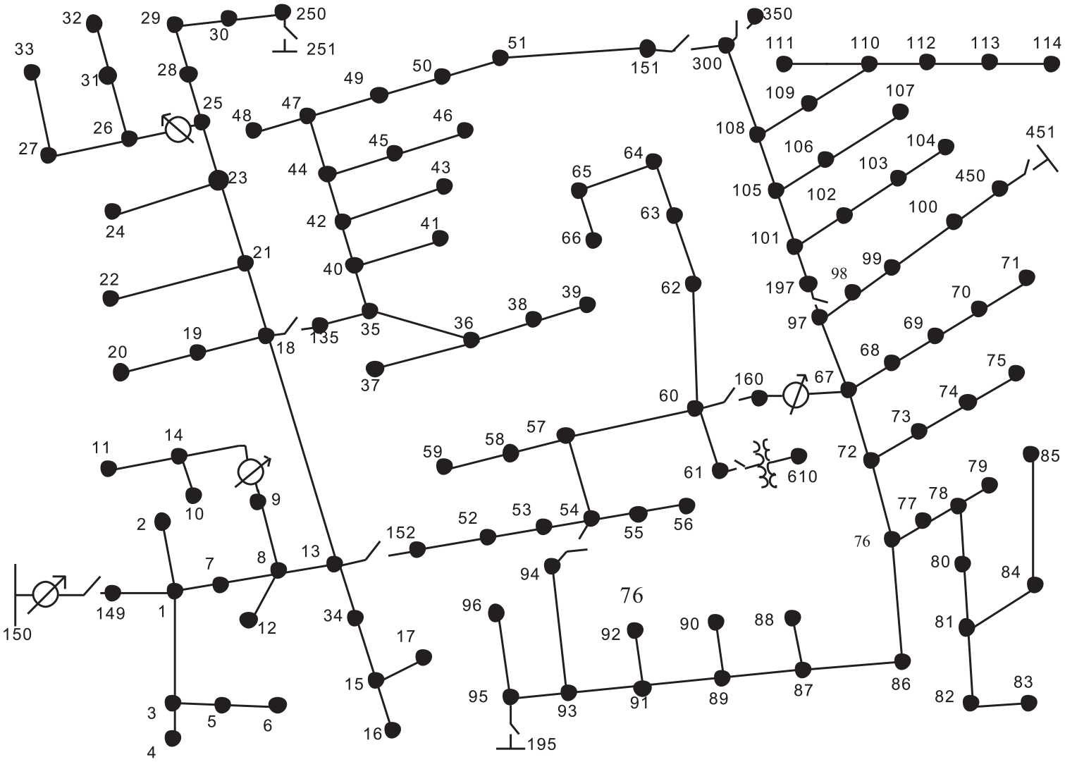
Implementation of standard IEEE 123-node feeder.
Results and discussions
The scenario is designed for a load of 60 kW. The photovoltaic cell produces DC voltage while the Wind turbine generated AC output. Both can be directly connected in the system to the respective load or through the inverter. This surplus energy generated by the DG is used to charge batteries initially and later support other microgrids or DERs within the same microgrid.
A fault in the MV side appeared followed by MG islanding at 100 ms. The system will deviate from the initial frequency initially in order to achieve stability. This action will cause some load to be shed due to frequency conditions. This load is later ramped up gradually to avoid load disconnection and frequency or voltage droop. The slow ramping up of frequency allows the reacceleration of motor loads after fault clearing. Droop control is practiced, and the system achieves gradual stability without disconnection of load. However, there is a transient period for restoring system parameters, which also affects the inverter current and voltage. Outputs of simulations are displayed in Figure 16.
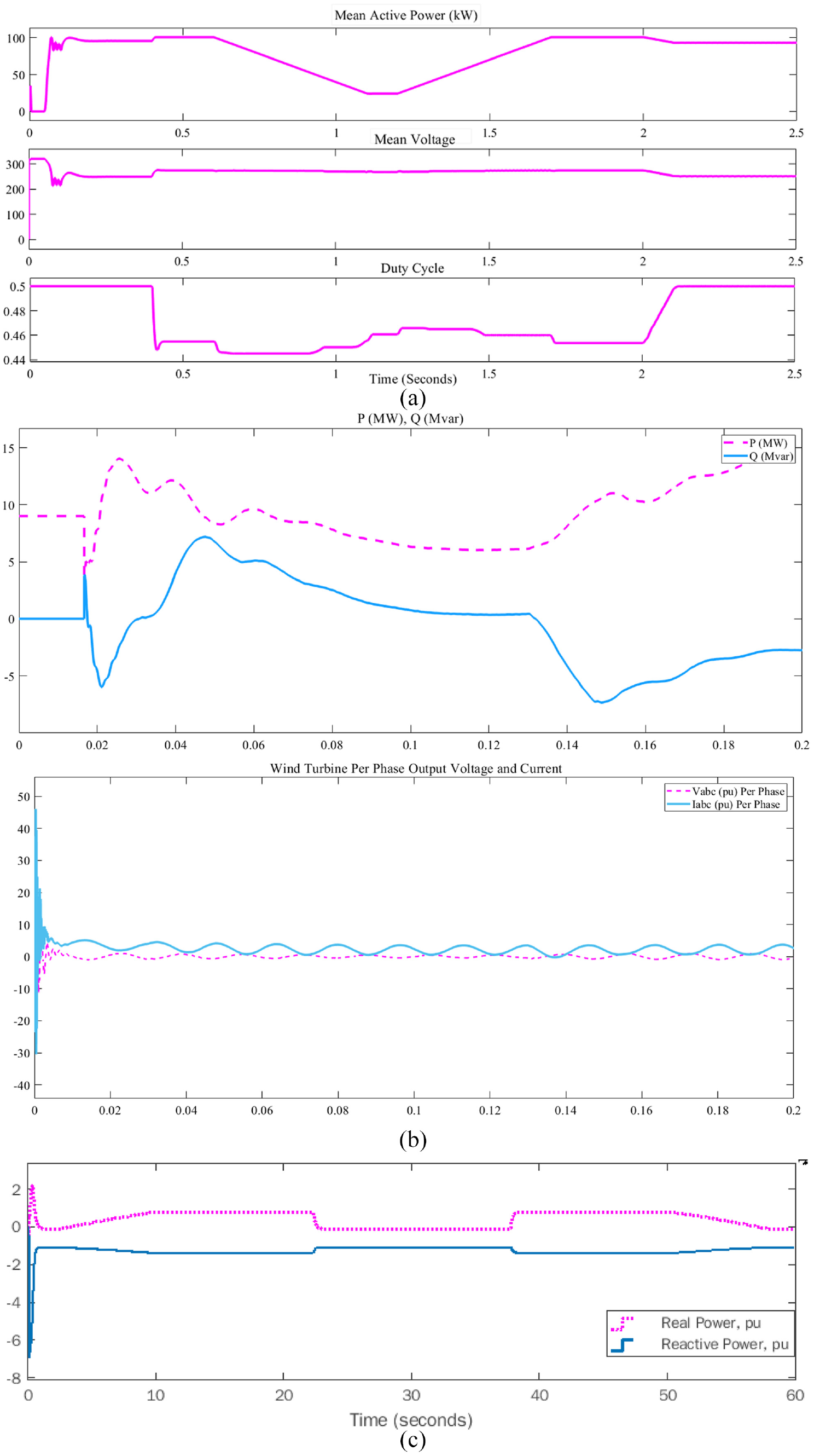
Output power and voltage of (a) photovoltaic cells, (b) wind turbine, and (c) frequency variation output.
The fault command is communicated to MGCC through PMU. In case of fault from the transmission line of the main grid, two operations are performed. The first microgrid gets disconnected from the main grid to restrict fault current from reaching the microgrid and damage system stability. PMU operating time is kept 50 ms under the fault duration time. In parallel to this operation, the load is shifted to storage cells in order to avoid voltage and frequency droop caused by the sudden disconnection of the main grid. The availability of DERs is checked by MGCC and communicated to MC and LC for slow shifting load to DER. The load gets shifted back to DER for the duration of MG islanded operation.
It can be observed from the graphs in Figure 16 that when the batteries are connected to the system, the system initially charges the batteries. In case of fault, the load is shifted to batteries. This also leads to a transient period where voltage is dropped for a certain period before it regains its nominal value. For a transient period, there may be a slight voltage drop as a matter of 1–2 s which can be observed in both cases, that is Photovoltaic cell (Figure 16(a)) and Wind turbine (Figure 16(b)). The islanded operation is observed for low and high loads. For low load, system initial frequency fluctuation is higher, but the system achieves stability in lesser time duration. For high load scenarios, the frequency fluctuation is low, the transient time is higher than in the low load scenario. To check the stability of the system for change in frequency, the grid frequency was reduced to 40 Hz and as shown in Figure 16(c), the system initially had some transient response before achieving stability. The estimated duration of transient response is 90 ms.
In this case, no inductive load was disconnected as the system reaccelerated after the elimination of fault. The main success of the system is in MG islanded operation when load connectivity and power supply to the load are maintained for sensitive loads. This feature offers higher system reliability. The state of charge of storage devices ensures the duration for which storage cells can support DER disconnection and fault rectification time allowance. Under both circumstances (high and low load conditions), a slow frequency restoration phenomenon can be observed, that results from the large MS time constants. During this process, the control system is responsible for a continuous matching between load and generation. The other aspect of this fault-tolerant control system is in case of a fault in one of DER. In this case, the load connected to a specific DER is shifted to batteries for the duration of fault occurrence. Again the fault is measured through PMU and communicated to MGCC before the load is shifted to storage units.
In Figure 17(a), the output voltages for the primary source which is the main grid in the proposed case, and PV voltage along with battery storage output is shown. In Figure 17(b), the state of charge of batteries over 1 day is observed. The simulation run time is 24 h. The negative battery power shows the batteries being used to supply uninterrupted power when generation through the wind is minimal. However, for sake of transition from the main grid to islanded mode, it happens in the period of a millisecond as shown in Figure 18. It shows the three-phase voltage supplied to the load in islanded mode. The primary source, in this case, is batteries that were charged before. When there is a power shortage, the system will transition from main grid to islanded mode and will be operated on batteries.
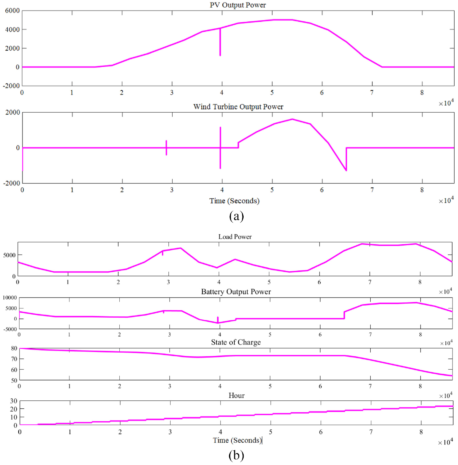
(a) Power output and (b) load power and the state of charge.
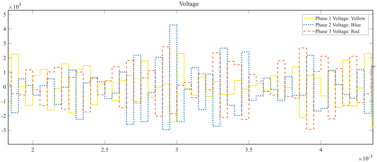
Three Phase voltage supplied to load in islanded mode.
Comparison with existing works
The following Table 2 presents an overview of the comparison of the proposed model with models presented in the literature for similar applications. The selection of the model depends on the requirements of the system and our proposed system is compared with six similar models. The performance parameters are selected based on efficiency, control pattern, complexity, function, and applications to achieve a fault-tolerant system for a DER-based microgrid. The results are compared for achieving the goal of a fault-tolerant control system for DER-based microgrid. It can be seen from the comparison that all proposed systems have their own merits and demerits.
Comparison with other studies.
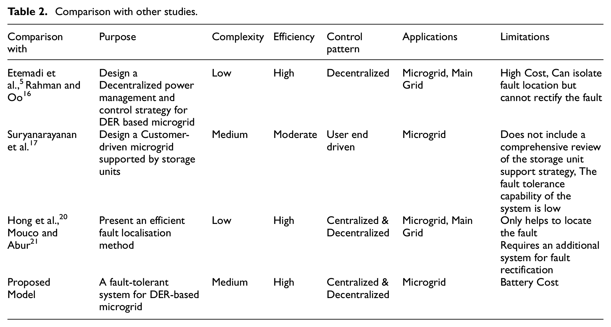
Etemadi et al. 5 and Rahman and Oo 16 proposed mathematical modeling for isolated microgrids based on DERs and discussed distributed generation in which the part of the system is disconnected, and load is shifted to alternate resources at the time of fault occurrence. The main idea is to keep the power coordinated within the microgrids and regulate the voltage in case of faults. However, the proposed methods only worked for isolating the faulty part and did not remove it, that ultimately burdened the overall system. Even though the models were efficient in terms of regulating the voltages and keeping low latency, with low complexity, nonetheless the lack of isolation of fault acted as a constraint to the methodology. As a step forward, in Suryanarayanan et al., 17 the authors proposed system support in the face of faults, through storage units while discussing the need for DERs and efficient interfaces for storing the energy, not only through batteries but in the form of capacitors and flywheels. However, the proposal although promising failed to bring up support in terms of simulations.
Hong et al. 20 and Mouco and Abur 21 used PMUs along with techniques like short circuit analysis and ordinary least squares estimation for the detection of faults. While the proposed methods were highly efficient in the detection of fault by sensing the anomalies in voltage and current using PMUs installed at specific places within the network, however, the rectification of those faults that is equally important in the fault tolerance phenomenon is absent in these methodologies.
Building upon the amazing work done by these researchers, in this paper, we have proposed a method that covers the shortcomings of these previous techniques by not only detecting the fault but also isolating and removing it while keeping the system robust and resilient. The proposed techniques are also verified through simulations based on standards like IEEE 123-node feeder and several generation sources with pre-defined active and reactive power that prove the improved efficiency as compared to the previous works as shown in Table 2.
Conclusions
The fault-tolerant system improves system reliability by incorporating storage units and PMUs in the microgrid system. This system encourages DER and microgrid utilization in the power system. The overall success of the system is based on power continuity to sensitive loads and low investment cost with lesser complex system. This paper proposed the utilization of DERs as the primary source while the main grid shares the peak load. The paper also discussed the application of PMUs to record current and voltage values. The simulation results showed the possibility of shifting load to storage units for the islanded mode to supply continuous power supply. The PMUs improved fault detection systems with their high performance. In this paper, our contribution was mainly focused on proposing a fault-tolerant system for DERs mainly PV, MT, SOFC, and batteries as storage devices.
The proposed fault control system is for the distribution network and the power network is Microgrid connected to MV and a two-step hierarchal control system (1) MGCC, (2) MC and LC. MGCC act as director of operations and control. In islanded mode, LC and MC take charge based on either single operation mode or multiple operation modes. The proposed FTC takes into consideration multiple fault conditions (1) Operation in islanded mode, (2) Discontinuity of power supplied from any or multiple DERs, (3) Overcoming the impact of change in grid dynamics, and (4) Overcoming reverse power flow faults.
The system was tested in light of results from mathematical modeling and design simulation which show minimal latency rate against the demand response and quick isolation of fault location. A comparison with existing works also demonstrated the superior performance of the proposed fault-tolerant power system using PMUs.
In light of the results from this paper, possible future directions can be:
1: Installation of load classification system at distribution end for distribution side load management (DSM).
2: Designing a system that can stay on islanded mode for a longer duration by transferring a centralized system to multiple decentralized islanded independent systems.
3: Integrating Internet of Things (IoT) in the power system for load data analysis for a smarter control strategy of the energy system.
Footnotes
Appendix
Declaration of conflicting interests
The author(s) declared no potential conflicts of interest with respect to the research, authorship, and/or publication of this article.
Funding
The author(s) received no financial support for the research, authorship, and/or publication of this article.