
Abstract
The effect of adding different percentages of nano-graphene oxide (NGO) into the epoxy resin on the mechanical properties of NGO/epoxy and maximum peeling force of fiber-metal laminates (FMLs) with composite cores are investigated in this paper. Three different percentages of NGO including 0.1, 0.35 and 0.50 weight percentages (wt. %) are used to fabricate the tensile test samples of NGO/epoxy. Hand lay-up method is used to fabricate FML specimens with glass fiber reinforced plastic (GFRP) core and aluminum faces. Tensile tests are examined and the Young’s modulus and ultimate stress of NGO/epoxy samples are determined. It is found that after adding of 0.1 wt. % of NGO into the epoxy resin, the ultimate tensile strength decreased by 13.4% from 25.3 to 21.9 MPa. Moreover, using peeling test, the separation force between aluminum faces of Al/GFRP laminates are obtained. Based on the results, when 0.1 wt. % of NGO is mixed with the epoxy, the maximum peeling force of FML increases by 16% and amounts to 4 N/mm. Based on the results, when NGO is used next to micro fibers in the construction of composite core, they have an effective role on the interlayer adhesion of fibrous composites.
Keywords
Introduction
Fiber-metal laminate (FML) materials are a group of composite family that have sandwich structures and usually made of a fiber-reinforced plastic layer as a core and two metal layers as upper and lower faces. Because two different materials are employed in FML structures, they are also known as hybrid composites. 1 FMLs are significant parts in the structure of aircrafts, automobiles, rail transport and many other means of human life. They have excellent mechanical, thermal and electrical properties along with high corrosion resistance and outstanding strength to weight ratio compared to conventional composite laminates. 2 Shanmugam et al. 3 combined the titanium alloy (Ti6Al4V) and ultrahigh molecular weight polyethylene fiber and made a thermoplastic FML. Myung et al. 4 investigated the mechanical properties and low-cycle fatigue behavior of woven-type glass-fiber reinforced plastic (GFRP) coated on one side of an Al 6061 aluminum alloy plate base on the GFRP layer thickness. Hua et al. 5 investigated interlaminar fracture toughness of glass reinforced aluminum laminates with different fiber orientation using experimental and finite element methods. Khalid et al. 6 studied the interlaminar shear strength (ILSS) of carbon fiber reinforced aluminum laminates (CARALL), glass-reinforced aluminum laminates (GLARE) and aramid-reinforced aluminum laminates (ARALL) under different displacement rates. Their results indicated that the ILSS of CARALL was higher than GLARE and ARALL at all displacement rates.
Jakubczak et al. 7 experimentally investigated the effect of the thermal cycles on ILSS and microstructure of CARALL modified by additional glass interlayer. They stated that the strength is not dependent on thermal cycles. Bieniaś et al. 8 presented the influence of hygrothermal conditioning of hybrid fiber metal laminates, consisting of alternating layers of a 2024-T3 aluminum alloy and carbon fiber reinforced polymer, on the delamination and ILSS of FMLs. Banat and Mania 9 studied the nonlinear buckling and failure of thin-walled FMLs under axial pressure. Li et al. 10 investigated the multilayers with combinations of different fiber directions and fiber types to face the complicated stress distributions in applications. Lopes et al. 11 developed a numerical code to predict the effects of manufacturing-induced porosity on the interlaminar shear strength of FMLs. They modeled porosity in the geometry of the interface by setting some of these elements to a pre-delaminated state. Yang et al. 12 investigated the effect of adding nanoparticles of polydopamine on mechanical properties of epoxy resin. Megahed et al. 13 experimentally investigated the effect of adding different nanoparticles on mechanical properties of epoxy resin. Khalil et al. 14 examined the effect of adding aluminum nanoparticles on interlayer adhesion between aluminum and epoxy resin. Jojibabu et al. 15 investigated the effect of carbon nanotube addition on epoxy resin and concluded that by adding nanoparticles, shear strength increased by 26%. Aghamohammadi et al. 16 investigated the effect of several surface treatment of aluminum alloy on the flexural behavior of an FML. Hosseini Abbandanak et al. 17 studied the effect of graphene nanoplatelets (GNPs) on the flexural and charpy impact properties of FML plates. They observed that by adding 0.1 wt. % of GNPs, the flexural strength, modulus and impact strength improved and also adding 0.25 wt. % and 0.5 wt. % GNPs reduced these attributes compared to the FMLs containing 0.0 wt. % GNPs. Shifa et al. 18 shew that adding multi-wall carbon nanotubes to CARALL, due to the weakening of the interface between the face and core, worsens the interlayer properties of CARALL. Süsler et al. 19 examined the effect of surface treatments on hot-pressed GLARE laminates. They applied sandpapering, degreasing and both degreasing and sandpapering on AA6061-T6 sheets in order to contribute the improvement of the ILSS. The results of their work stated an increase between 29% and 37% for surface-treated laminates against untreated one.
The effect of nano-graphene oxide (NGO) dispersion into the epoxy resin on mechanical characteristics and interlayer adhesion of FMLs are investigated in the current research. Different weight percentages of NGO (0.1, 0.35, and 0.5) are added in to the epoxy resin and tensile test specimens are fabricated. Young’s modulus and ultimate tensile strength of NGO/epoxy specimens are measured. Moreover, FML specimens including 0.1% NGO/glass/epoxy, 0.35% NGO/glass/epoxy and 0.50%NGO/glass/epoxy composites cores are manufactured. Universal tensile testing machine is utilized to determine maximum peeling force of FMLs with aluminum faces.
Experiment
Materials
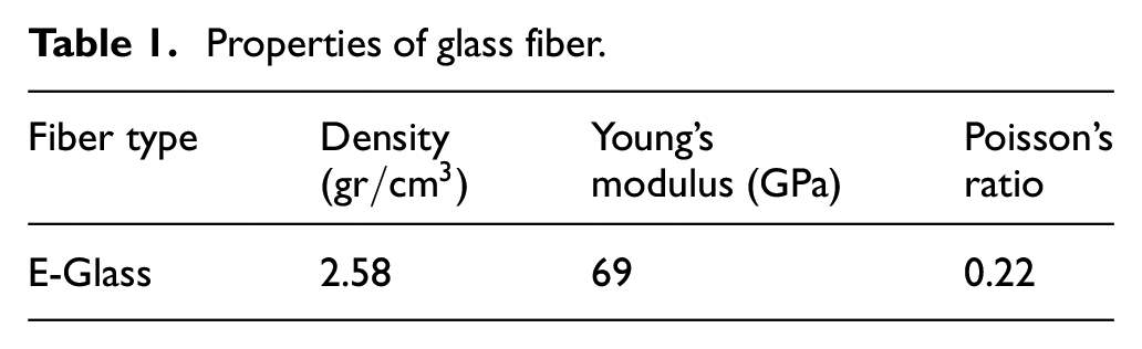
LR 630 epoxy resin and LH 630 hardener are used. T100 Glass fibers are acquired from JSC Refractory (Belarus) Co., Ltd. The fiber properties are listed in Table 1. Aluminum alloy 2024-T3 with 0.7 mm thickness is utilized. Multilayer NGO has been used in this research. SEM (scanning electron microscopy) and TEM (transmission electron microscopy) images of NGO layers are illustrated in Figure 1(a) and (b) respectively. As the figure shows, the thickness of nanolayers is less than 100 nm.
Properties of glass fiber.

Microscopic images of nano-graphene oxide, (a) SEM image and (b) TEM image. 20
Fabrication process
Dispersion of NGO into the epoxy resin
NGO is added into the epoxy resin as nanofiller reinforcement. To achieve a homogeneous dispersion of NGO, mechanical mixing along with ultrasonic bath are utilized. Epoxy resin is mixed with graphene oxide for 10 min by a magnetic stirrer (Figure 2(a)), then the mixture is placed into the 70 W ultrasonic bath for 22 min (Figure 2(b)). These processes are repeated two times to achieve a homogeneous mixture.

Dispersion of nano-graphene oxide (NGO) into epoxy resin, (a) magnetic stirrer and (b) Ultrasonic bath.
Manufacturing of NGO/epoxy tensile test specimens
Resin tensile test samples were made according to ASTM D638 standard. 21 The samples were fabricated with different weight percentages of NGO (0.1, 0.35, and 0.50 wt. %) and without NGO. To make tensile test samples, a two-piece aluminum mold was employed as shown in Figure 3(a). Epoxy tensile test specimens and NGO/epoxy samples are illustrated in Figures 3(b) and 4 respectively.
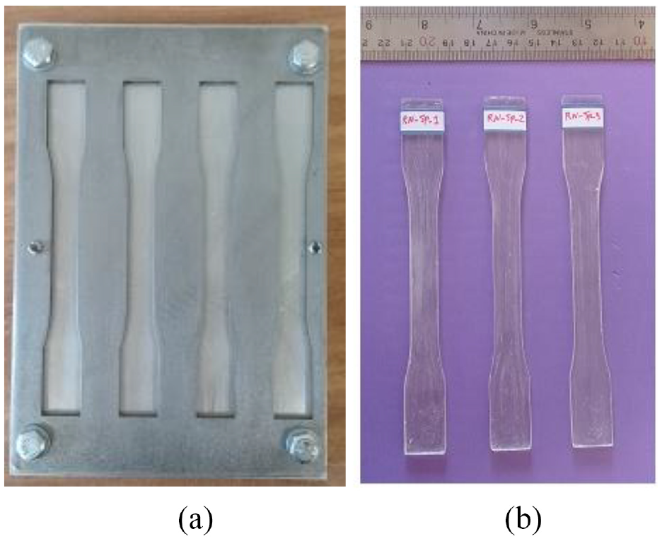
(a) Aluminum mold for manufacturing of resin tensile test specimens and (b) neat epoxy tensile test specimens.

Tensile test specimens (left to right), neat epoxy, 0.1%NGO/epoxy, 0.35%NGO/epoxy, and 0.50%NGO/epoxy.
Manufacturing of FML plates
In order to prevent separation, and to achieve proper bonding between metal faces and composite core, the aluminum sheets surfaces were cleared of any contamination including oil and grease. This is done in four steps by solutions containing acetone, NaOH, and sulfo-chromic acid. After each step the aluminum sheets are rinsed with hot water. Figure 5(a) to (d) show these steps.

Aluminum sheet surface cleaning, (a) acetone cleaning, (b) NaOH etching, (c) sulfo-chromic acid etching, and (d) rinse with hot water.
The FML specimens for peeling tests were made according to the ASTM D1876. 22 The interlayer composite cores of peeling test samples consist of four layers of woven glass fibers and epoxy resin. Four FML plates including 0.1%NGO/epoxy, 0.35%NGO/epoxy and 0.50%NGO/epoxy cores are fabricated by hand lay-up method. Further, a vacuum pump was employed in order to compress the aluminum faces and composite core layers of FML together. FML specimens were cured under vacuum for 24 h at room temperature. Figure 6 shows the steps of manufacturing process of FML plates.

Manufacturing steps of FMLs.
Tensile test of neat epoxy and NGO/epoxy specimens
Instron 8802 universal testing machine is used to examine tensile tests (Figure 7(a)). Specimen under tensile load is shown in Figure 7(b). An extensometer is employed to measure length change of gage length of the sample. In order to determine the average values of the results, three identical samples of each material type were tested.
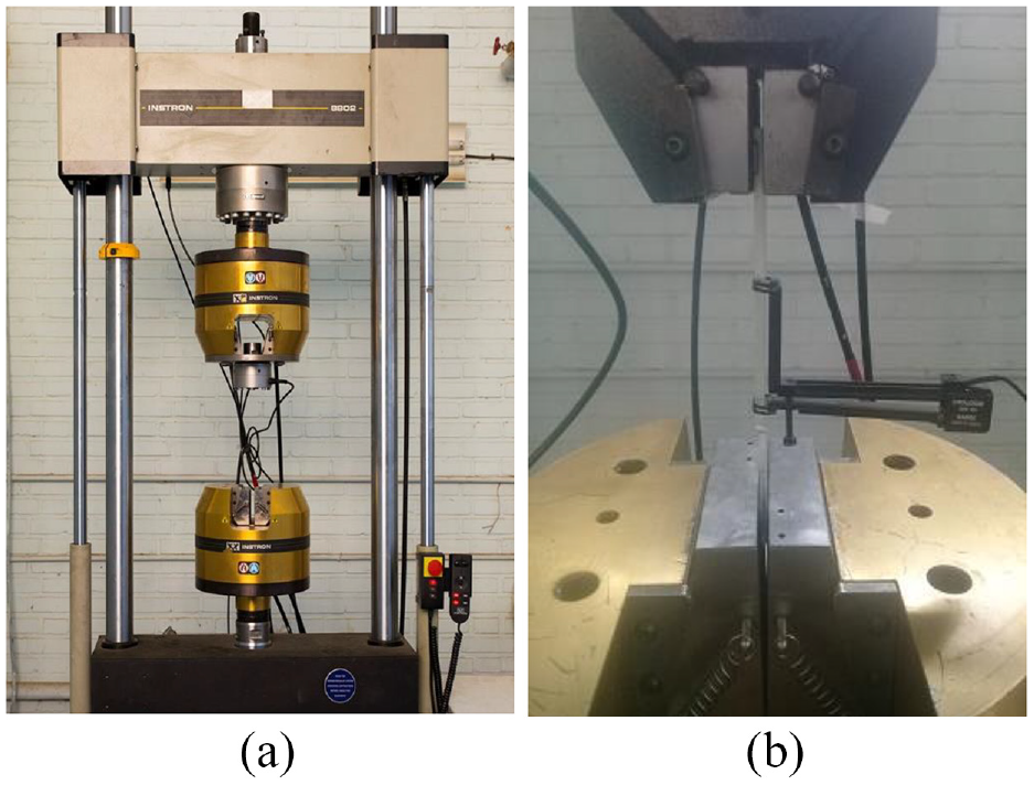
(a) Instron 8802 universal testing machine and (b) neat epoxy test specimen under tensile loading.
Peeling test
Generally, the goal of a peeling test is to determine the adhesive strength of the material or the strength of the adhesive bond between two materials. An Instron 8802 universal testing machine is used to execute the peeling tests. Three T-peel specimens are extracted from each FML plate. The bent and unbounded ends of the fabricated test specimen (Figure 8(a)) are fixed in the test grips of the tension testing machine. Schematic of T-peel test is shown in Figure 8(b).

(a) Manufactured T-peel specimens and (b) schematic of FML T-peel test.
Results and discussion
Tensile test
Neat epoxy and NGO/epoxy specimens with different wt. % of NGO are subjected to tensile test and their Young’s modulus and ultimate stress values are extracted. Three samples of each type of material are tested. The average values along with the standard deviation for Young’s modulus and ultimate stresses are shown in Figures 9 and 10 respectively. For a better comparison, these values along with the comparison of the parameters with respect to those of the sample without graphene are summarized in Table 2. As the results show, addition of nano-graphene to epoxy does not have much effect on the value of Young’s modulus. Also, adding 0.1 wt. % of NGO into the epoxy resin is reduced the ultimate stress by 13.6%. It seems that in these samples, nanoparticles play the role of impurity and cause stress concentration. By adding a higher percentage of nanoparticles into the resin, the ultimate stress values show increases of 6.6% and 11.7% compared to the sample without nanoparticles and reaches values of 27 and 28.3 MPa for 0.35%NGO/epoxy and 0.50%NGO/epoxy, respectively.

Young’s modulus of neat epoxy and NGO/epoxy materials.

Ultimate stress values of neat epoxy and NGO/epoxy materials.
Young’s modulus and ultimate stress values of specimens (average values).

Peeling test
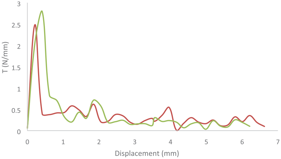
Having performed the peeling tests on the FML beams with different core materials, separation force per unit of width (T) versus displacement between tow aluminum faces of FML samples are obtained. Force-displacement graphs for FML specimens including glass/epoxy, 0.1%NGO/glass/epoxy, 0.35%NGO/glass/epoxy and 0.5%NGO/glass/epoxy cores are illustrated in Figures 11 to 14, respectively. Maximum peeling force per unit of width (Tmax) is extracted from each graph and the average values along with the standard deviation error bars are illustrated in Figure 15. According to the results, addition of 0.1 wt. % of NGO into the epoxy resin of core material increases the value of Tmax of FML, and by adding more weight percentage of NGO into the resin, the interlayer adhesion is decreased. Maximum peeling forces of all FML specimens along with the change percentage of this parameter are summarized in Table 3. According to the results, by adding 0.1 wt. % of NGO into the epoxy resin of glass/epoxy core, Tmax is increased by 16% and amounts to 4 N/mm. As the table shows, adding more percentages of NGO into the epoxy resin of the glass/epoxy decreases the maximum peeling force. Tmax equals 2.64 N/mm for FML samples with 0.5%NGO/glass/epoxy core which indicates 24.5% decrease with respect to that of FML with glass/epoxy core.
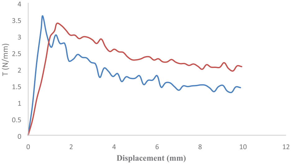
Separation force per unit of width (T) versus displacement between tow aluminum faces for FML specimens including glass/epoxy core.

Separation force per unit of width (T) versus displacement between tow aluminum faces for FML specimens including 0.1% NGO/ glass/ epoxy core.

Separation force per unit of width (T) versus displacement between tow aluminum faces for FML specimens including 0.35% NGO/ glass/ epoxy core.
Separation force per unit of width (T) versus displacement between tow aluminum faces for FML specimens including 0.5%NGO/glass/epoxy core.

Peeling test results for all specimens.
Maximum Peeling force per unit of width (Tmax) of FML specimens with different core materials (average values).

Although, according to the Table 2, adding 0.1 wt. % of NGO into the epoxy resin decreases the ultimate stress of the NGO/epoxy material, adhesion between 0.1%NGO/glass/epoxy layers of FML develops the increase of the maximum peeling force of these specimens with respect to that of FML including glass/epoxy core. After separation of aluminum faces of FMLs, some pictures of the separated surfaces are prepared. Upper and lower aluminum faces of FML specimens including glass/epoxy core and 0.1%NGO/glass/epoxy are demonstrated in Figure 16. As the figure shows, in both cases (Figure 16(a) and (b)), adequate adhesion is observed between the core and the aluminum faces, and the separation happened from the area between the layers of composite core. As it can be seen in Figure 16(a), the separated surface has a uniform state in FML with glass/epoxy core, while in Figure 16(b), FML with 0.1%NGO/glass/epoxy core, the separated surface has a non-uniform state. This can be related to improving the adhesion between the layers of the 0.1%NGO/glass/epoxy composite core in some regions.
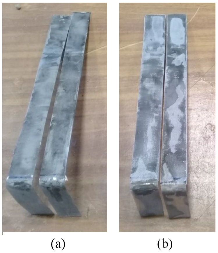
Upper and lower aluminum faces of FML specimens, (a) FML with glass/epoxy core and (b) FML with 0.1%NGO/glass/epoxy core.
Conclusion
In this study, tensile properties of epoxy, reinforced with different percentages of nanographene oxide (NGO) is presented. Neat epoxy, 0.1%NGO/epoxy, 0.35%NGO/epoxy and 0.50%NGO/epoxy tensile specimens are examined. Based on the results, 13.6% reduction of ultimate stress is observed for 0.1%NGO/epoxy with respect to that of neat epoxy. Further, employing the peeling test, the adhesion between upper and lower faces of of FMLs with aluminum faces and composite cores is investigated. FML specimens including glass/epoxy, 0.1%NGO/glass/epoxy, 0.35%NGO/glass/epoxy and 0.5%NGO/glass/epoxy cores are tested. As the results indicates, maximum peeling force of FML with 0.1%NGO/glass/epoxy is increased 16% with respect to that of FML including glass/epoxy core. It is concluded that although the addition of NGO to the epoxy resin reduces the ultimate stress of the NGO/epoxy material, when this nanofiller is used in the NGO/glass/epoxy composite structure, it can improve the interlayer adhesion.
Footnotes
Acknowledgements
The authors thank Mr. Hamidi from the Shahrood University of Technology for cooperating in doing this research.
Handling Editor: Chenhui Liang
Declaration of conflicting interests
The author(s) declared no potential conflicts of interest with respect to the research, authorship, and/or publication of this article.
Funding
The author(s) disclosed receipt of the following financial support for the research, authorship, and/or publication of this article: This work was supported by the Shahrood University of Technology research grant.
Data availability statements
The datasets generated during and/or analyzed during the current study are available from the corresponding author on reasonable request.