
Abstract
Owing to the existing problems of the temporary shield support device in a coal mine, such as considerable component weight, difficult disassembly, and large chamber installation, the design of the temporary rectangular shield support device was optimized. A module division method combining the functional analysis method and a similar feature clustering method was proposed, which completes the division of the functional module and establishes the structural module. A structural optimization method of “variable density topology optimization, parameter sensitivity analysis and Optimal Space-Filling Design (OSF)” was proposed. A variable-density topology optimization model of the device was established using the variable-density topology optimization method. The key variables of the device were determined using a parameter sensitivity analysis. The sample points of the critical variables were generated using the optimal space-filling design method, the approximate response surface models of mass, displacement, and stress were constructed, and the optimal solution of the device’s weight was obtained under the constraint conditions of pressure and displacement. A lightweight matching method of modularization based on transportability, disassembly, maintainability, and reliability was proposed, and the optimal matching scheme for the volume and mass of the device was determined. As a result, the weight of the temporary shield support device was reduced by 11.2%, and the maximum stress was reduced by 13.4%, under the premise of ensuring reliability. It realizes the convenience of transportation and high efficiency of assembly and disassembly in different design requirements, which is of great significance to accelerate the intelligent construction of coal mine.
Keywords
Introduction
As a critical link in coal mining, the efficiency and reliability of coal mine supports play vital roles in determining the speed of roadway formation. In roadway excavation, supports are generally divided into temporary and permanent supports. Traditional support is time-consuming, laborious, and carries security risks. It fails to solve the problems of “fast excavation and slow support,”“parallel of excavation and support,” and so on. Aiming at the difficult problem of mining under complex geological conditions where gangue and spalling coexist in a large-section roadway, our team developed an intelligent mining robot system for coal mines, this system has been applied in domestic coal mines, where the tunnel penetration exceeds 45 m in a single day, which realized parallel and continuous operations of excavation, support, and transportation,1,2 laying a solid foundation for promoting intelligent mining of coal roadways. However, it cannot be ignored that the rectangular shield temporary support equipment in a tunneling robot system has large volume, transportation, installation, disassembly, maintenance, and other difficulties. It is only applicable to the environment of large section roadway with good conditions, and it is difficult to adapt to the transport and disassembly requirements of the shield under complex geological conditions. Therefore, in this study, a lightweight optimization design for a rectangular shield temporary support device was developed based on a modular lightweight design idea.
Lightweight designs are widely used in automobile and aerospace fields. There are three ways to lighten the weight: material lightening, process lightening, and structure lightening. Among these, lightweight structures can be divided into topology, shape, and size optimization. Topology optimization is mainly applied to the conceptual design stage, shape optimization to the basic design stage, and size optimization to the detailed design stage.3–5 In terms of lightweight materials, Iqbal et al. 6 proposed using a new type of composite plastic to make a lightweight multifunctional avionics shell. The results showed that a lightweight design with an equipment mass reduction of 25% was achieved using this lightweight composite material, significantly reducing research and development costs. Jung et al. 7 carried out a multi-material optimization design of a special-shaped structure based on the steel-aluminum material mixing scheme, and the mass of the optimized steel-aluminum mixed structure was reduced by 8.0% compared with the original aluminum alloy structure. From the aspect of process lightweight, Sun et al. 8 used a lightweight process to complete the optimization design of car doors, and the results showed that 42.1% weight reduction was achieved by improving the structural characteristics of the doors. Xiong et al. 9 comprehensively considered the modal and stiffness properties of the component structures. They carried out a structure-material integrated lightweight design, which achieved a weight reduction of 4.12 kg, with a weight reduction rate of 1.32%, and reduced the material cost. From the aspect of structural lightweight, Su et al. 10 adopted the topology optimization method to ensure the reliability of the structure and realize a lightweight design of the stamping die parts by approximately 18%. Simultaneously, the die structure was redesigned according to the manufacturing technology and initial optimization results to ensure the manufacturability of the new structure. Viqaruddin and Reddy 11 adopted a topology optimization method to optimize the structure of an aluminum-alloy automobile control arm. They achieved an 8.2 kg weight reduction of the component with a weight reduction rate of 41%, and the optimized control arm met the strength and stiffness requirements. Chai et al. 12 aimed at the problem that the quality of the butt joint structure in tower assembly construction is high, which has a significant influence on the work of aerial workers, and established a simulation model using ANSYS software, given the optimization constraints, by adjusting the structural parameters. The butt structure was reduced by approximately 39% and the lightweight design of the equipment was completed. Zhang et al. 13 built a response surface model of a brake caliper based on the OSF algorithm, used the caliper mass as the primary output parameter, and completed the lightweight design of the brake caliper with a weight reduction of 15.4% through multi-objective optimization using MOGA. Hou et al. 14 optimized and improved the size and shape of a special-shaped structural joint. Compared with the pre-optimization, the weight of the optimized structure was reduced by 86.5 kg, the weight reduction rate was up to 10%, and the bending stiffness was significantly improved. Tang et al. 15 proposed a lightweight optimization method based on multiple working conditions and objectives, and completed the optimization design of the frame of a crewless sightseeing vehicle. The results show that the optimized structure can reduce the weight by 5.4% while satisfying the strength requirements of various working conditions.
Owing to the particular requirements of the explosion-proof performance of coal mine equipment, some new lightweight materials cannot be used. Simultaneously, the traditional lightweight design method leads to prolonged research and development cycles, cost increases, complex manufacturing processes, and other problems. Therefore, this paper proposes a lightweight optimization method that combines topology optimization with parameter sensitivity analysis and size optimization to realize a lightweight design for the temporary support device of a rectangular shield. First, the force of the temporary support device of a rectangular shield was studied and analyzed. Second, a three-dimensional model was established for the module division of the quick support device of the rectangular shield. The lightweight design was carried out based on the variable density topology optimization method in structural optimization to obtain the best structural performance. The optimization results were used as the basis for size optimization to determine the optimal combination of structural parameters and further realize the lightweight design of temporary rectangular shield support device.16,17 According to different roadway handling and disassembly requirements, the modular lightweight matching research is carried out for modules with large volume and mass ratios, and optimal matching scheme is determined. Finally, the finite element software was used to simulate and analyze the key modules to verify the reliability of the lightweight design.
Overall design scheme of temporary support device for rectangular shield
After the coal mine roadway is cut, the temporary support bears all the pressure on the roof, which must have sufficient strength and stiffness to adequately protect personnel and equipment. The temporary support device of the rectangular shield was composed of temporary supports I and II, both of which contained an upper shield body, lower shield body, hydraulic cylinder, and guide column. The hydraulic cylinder adjusts the pressure on the roof to form a safe support, as illustrated in Figure 1.

Diagram of temporary support device for rectangular shield: (a) diagram of temporary support system and (b) diagram of temporary support device I.
Force analysis of temporary support device of rectangular shield
It is assumed that the load on the top of the roadway is uniformly distributed, and the gravity of the rock that naturally balances the arch is uniformly distributed on the roof shield; the relationship between the supporting force required by the temporary supporting device and the gravity of the balanced rock is obtained according to the Platts theory, and the formula of supporting strength is as follows:


where F is the supporting force, kN, s is the supportive area (m2), q is the uniform distribution load in the natural balance arch per unit area (kN/m2), γ is the rock bulk density (kN/m3), b is the vector height of the natural balance arch (m), f is the Platts strong coefficient, f = 3, k is the influence factor, k = 0.6.

where a1 is the span of the natural balance arch (m), a is half the roadway width (m), h is the roadway height (m), φ is the internal friction angle of the rock.
Design of rectangular shield temporary support device
Module division of temporary support device of rectangular shield
According to the modular design concept, the functional analysis method was adopted to decompose the rectangular shield temporary support device, 18 which was divided into support, connection, and bearing functions, and the minimum function element was determined, as shown in Figure 2. The similarity feature clustering method was used to combine the unit structures with high similarity. 19 The upper left-side shield and the upper right-side shield had the same function and similar structural configuration, and they were divided into the upper side shield module. The lower left-side shield and the lower correct-side shield had the same function and similar structural configuration, and they were divided into the lower side shield module, and the module division of the temporary rectangular shield supporting device was completed.

Division diagram of functional modules of rectangular shield temporary support device.
Roof shield module
The roof shield module directly bears the weight of the roadway to form a natural balance of the rock in the arch when the temporary support device is operating, which is the most important component of the temporary shield support. It is necessary to ensure sufficient strength and stiffness, and a structural design combining the frame with top plate protection can ensure the reliability of the design and realize a lightweight design. The hydraulic cylinder lifts the upper side shield to drive the roof shield to support when working and to protect the safety of the equipment and personnel in the shield body.
Lower and upper shield module
The temporary support lower-side shield module bears the weight of the upper shield, and as the carrier of the hydraulic cylinder, it has a heavy load; therefore, the structural strength, stiffness, and stability must be higher. The hydraulic cylinder installation groove and guide hole are located on the upper and lower sides of the shield body; therefore, the overall structure layout of the lower side shield body should be reasonable to avoid center of gravity instability and other safety risks.
Both the lower and upper side shields adopt a center support design; that is, the axis of the support intersects the middle line of the upper and lower side shields at a point. This support method can increase lateral stiffness, reduce horizontal displacement, and improve the internal force distribution of the structure. A layout of two guide columns inside and two hydraulic cylinders outside was adopted, which can make the structural force uniform, ensure the reliability of the structural design, and prolong the service life.
The upper-side shield module of the temporary shield support was associated with the lower shield body through the hydraulic cylinder and guide column, and the distribution of the guide hole and installation groove of the hydraulic cylinder were the same as those of the lower-side shield body.
Base module
The base module bears the entire cutting device. In addition to sufficient strength, the design size should be considered. The grounding specific pressure in a coal mine refers to the nominal grounding specific pressure, that is, the ratio of the total gravity of the shield body to the ground area of the base, which is expressed by the formula:

Where Pd is the specific grounding pressure of the temporary support device (MPa), G is the dead weight of the device (kg), Sd is the contact area between the base and the ground (m2).
The self-weight of the rectangular shield temporary support device was determined: the larger the contact area between the base and the ground, the smaller the grounding specific pressure, which consumes more steel and increases the weight, which is not in line with the lightweight design concept. Therefore, a lightweight design should be realized as far as possible under the condition of meeting the permissible ground-specific pressure, and the Coal Mine Safety Regulations stipulate that the safety factor of coal mine equipment should not be less than 3, which ensures safety and simultaneously needs to achieve the goal of lightweight.
Module interface standardization
The interface combines modules into a system that determines the degree of modularization of the system. Therefore, standardization of the module interface is key to realizing modular design.
The primary function of the module interface of the temporary support device of the rectangular shield is to locate the relative positions between modules, restrict the degrees of freedom between modules, and complete the overall functional operation of the system. Similar functional modules should have the same module interface, which can be divided into two types: extension and embedded. Both the base and roof shields body have the function of bearing and supporting, which is defined as an extension interface in the interface design, the upper side shield body and the lower side shield body are used for supporting and connecting, and the interface is defined as an embedded interface, Figure 3 shows the tree diagram of module interface types.

Diagram of module interface type.
Lightweight optimization design
To realize a lightweight temporary support device with a rectangular shield, First, analyze the structural characteristics of the module division device to check whether there are defects in the design. Second, a lightweight design of the temporary support device was carried out based on topology optimization and size optimization using the structural optimization method. The optimal matching scheme of a modular lightweight device is finally determined through the fusion and matching of volume and quality information. The lightweight process is illustrated in Figure 4.

Lightweight optimization scheme diagram of temporary support device.
Analysis of structural characteristics of temporary support device with rectangular shield
The modular model of the temporary support device of the rectangular shield was imported into the Static Structural module in the ANSYS Workbench. The material used was Q345 steel; its material parameters are listed in Table 1.
Q345 steel material parameter list.

For the rectangular shield temporary support device, the automatic generation mode is used. The size of the model is large, if the grid division with higher precision is used for all the structures, it will cause a huge amount of computation and unnecessary waste of resources. If the grid division with low precision is used, the accuracy of the results will be insufficient and the simulation model will be inaccurate. Therefore, only the key parts of the device with high precision mesh refinement. According to the model size of the device and the mesh ratio, the mesh size is set to 50 mm, and the quality of the mesh determines the accuracy of the results, this paper uses the quality of grid cells to evaluate the grid division. As shown in Figure 5 below, the results show that the mass of tetrahedral mesh cells is mostly above 0.63, the mass of hexahedral mesh cells is all above 0.63, and the mass of prismatic mesh cells with higher precision is above 0.88. The grid division effect is good, and constraints and loads are imposed; in this paper, the roof shield body bear uniform load, the value is given as 800 kN, the base body bear 50 kN, and the safety factor of coal mine equipment is given as 3.5; that is, the safety stress of equipment should not be higher than 98.6 MPa, and the calculation is solved, As shown in Figure 6, the stress-displacement nephogram of the model indicates that the results are within the allowable range. No obvious design defects met the design requirements.

Diagram of grid quality.

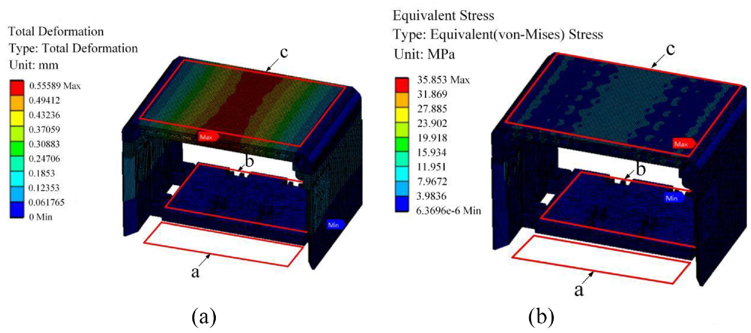
Nephogram of stress-displacement: (a) displacement nephogram and (b) stress nephogram.
According to the analysis of the displacement and stress cloud diagram in Figure 6, the displacement is mainly concentrated on the middle side of the roof shield. Since the device structure is no support in the space of the shield body and the shield body bears uniform load, the load on the shield can be regarded as the load on the simple supported beam. Therefore, the displacement is located on the middle side of the roof shield. In practice, because the shield body carries the cutting device, the material layout in area b of the device is located at the rear end of the device, and the material layout is asymmetrical before and after the device. Therefore, under the influence of the uniform load in area c and the material layout in area a and area b, the maximum displacement occurs in the front end of the roof shield.
The stress is mainly concentrated in the middle of the roof shield and the joint of the frame of the shield body. The front and rear ends of the roof shield module adopt the same support mode. When the roof of the temporary shield supporting device is under uniform load, the stress model of the shield body can be simplified as simply supported beam under load, and the maximum stress is located at both ends of the shield. In practice, because the material layout in area b of the device is located at the rear end of the device, the material layout is asymmetrical. Therefore, under the influence of uniform load in area c and material layout in area a and area b, the maximum stress is located at the front end of both sides of the roof shield.
The stress-displacement nephogram of the model indicates that the results are within the allowable range, and there are no obvious design defects and meet the design requirements. The results of displacement and stress are shown in Table 2.
Displacement and stress results table.

Topology optimization of key components
The Topology Optimization module based on ANSYS Workbench software adopts the variable density method for topology optimization design, with a maximum stress of less than 98.6 MPa and a maximum deformation greater than 0 as constraints and the weight of equipment as the optimization objective. The mathematical model is as follows:

where ρi is the pseudo-density of each unit, 0 < ρi < 1; ρi close to 1 indicates that the unit material needs to be retained, N is the number of units, σs is the maximum stress, [σ] is the allowable stress, and D is the maximum displacement.
The Topology Optimization module was added to the finite element model static structural solution, the optimization area was selected, different optimization target values were set, the original weights of 90%, 80%, 70%, and 60% were retained, and the results of varying topology optimization schemes were obtained. As shown in Figure 7, the density threshold is set to 0.4. If the unit density was less than 0.4, then the corresponding area was deleted. The shaded area in the figure is the area where the materials were removed after the iterative topology optimization solution, and the corrected model was established according to the topology optimization results.
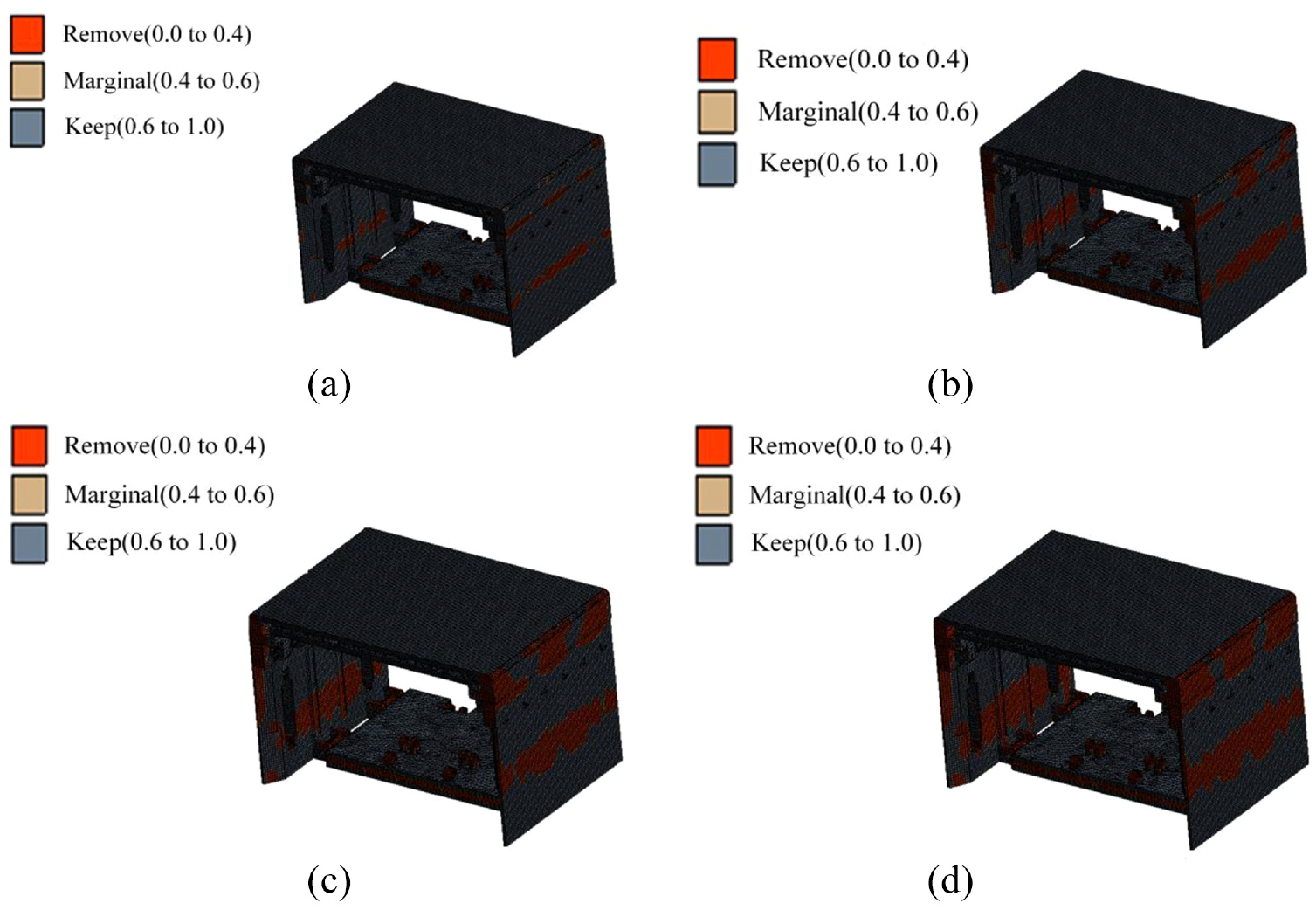
Diagram of topology optimization model: (a) keep 90%, (b) keep 80%, (c) keep 70%, and (d) keep 60%.
Four topology optimization models were compared and analyzed. The material removal areas were mainly concentrated on the two sides of the roof shield body, the lower side of the upper side shield body, the upper side of the lower shield body, and the base frame. Therefore, transition fillets were added to the roof shield sides of the original shield structure and the interface of functional modules to remove redundant materials, and reinforcement plates were added to the upper and lower shield material removal areas to increase stability, reduce the number of reinforcement plates for the base frame, and reduce the weight of the device.
The reinforcement plates of the base are located in area a, and the number of reinforcement plates is denoted as m. The weight, maximum stress, and maximum displacement of base module under different numbers are compared to select the most appropriate optimization model. The data pairs of base module ribbed slab plates are shown in Table 3.
Data comparison table of ribbed slab of base module.

The transition fillet on both sides of the roof shield is located in area b, and the fillet radius is denoted as R. The structural characteristic parameters of the roof shield under different fillet radius are compared, as shown in Table 4.
Related characteristic parameters of roof shield structure.

According to the topology optimization model, the upper and lower side shield removal area is denoted as c. Due to the particularity of the working environment and safety of the temporary support device, as well as the layout characteristics of the hydraulic cylinder and guide column of the device, the final window size of the material removal area was determined to be 450 mm × 600 mm, and ribbed slab were added to ensure the safety and reliability of the device.
By analyzing the data comparison table of the base ribbed slab of the device, it can be seen that when the number of ribbed slab is 3, the maximum stress and displacement of the base module will change greatly and the structure size of the device is large. For safety consideration, the number of reinforcement plates of the base is selected as 5 in this study. By analyzing the related characteristic parameters of the roof shield structure, it can be seen that when the transition fillet on both sides of the roof shield is 200 mm, the maximum stress and displacement of the roof shield will change greatly. Considering the structure and size of the device, the radius of fillet is 150 mm for model modification. Comparison of models before and after topology optimization is shown in Figure 8:

Comparison of models before and after topology optimization: (a) before topology optimization and (b) after topology optimization.
The structure characteristics of the model after the topology optimization of the device were analyzed. The material settings and boundary constraints of the device were the same as those described above. The comparison results of relevant data before and after device topology optimization are shown in Table 5.
Structure characteristic parameter table before and after topology optimization.

By comparing the structural characteristic parameters of the device before and after topology optimization, it can be observed that the maximum displacement of the device increases slightly compared with that before optimization, but it is still within the allowable range. The maximum stress of the device is slightly increased compared with that before optimization, because stress concentration is more likely to occur at the connection between the two sides of the roof shield and the upper shield body after topology optimization, and the local strength of the structure can be made up by size optimization in the subsequent process. The weight of the device is reduced by 6093 kg; The optimal layout of the device material is realized, and the next optimization design can be carried out.
Size optimization of key components
The topology optimization of a rectangular shield temporary support device provides an effective load transfer path and optimal material layout.20,21 The obtained model cannot be used as the final result of lightweight; however, it can be used as the basis of size optimization to avoid blindness in design.
Size optimization refers to the use of algorithms to find the optimal solution for the optimization target, at the same time, given certain constraints and boundary conditions to achieve a lightweight design. In the size optimization stage, the maximum stress was less than 98.6 MPa, the maximum deformation was greater than 0 as a constraint, and the weight of the temporary support device of the rectangular shield was further reduced as the optimization objective. The mathematical model is expressed as follows:

where xi represents the parameter of each design variable; m is the number of design variables; xmin and xmax are the limit values of the design variables; σs is the maximum stress; [σ] is the allowable stress; and D is the maximum displacement.
Sensitivity screening of design variables
The width of the upper side shield frame was x1, the width of the lower side shield frame was x2, the thickness of the shield plate was x3, the thickness of the top beam frame was x4, the thickness of the reinforcement plate of the top beam frame x5, and the thickness of the roof shield x6 are the main variable parameters for the design of the temporary support device, as shown in Figure 9; x1, x2, x3, x4, x5, x6 are taken as the design variables; after parametric processing in Solidworks, the three-dimensional model was imported into the ANSYS Workbench parameter correlation module for research, and the sensitivity of input variable parameters to output variable parameters was obtained, as shown in Figure 10; p1–p6 correspond to parameters x1–x6, p1, p2, p4, and p6 are sensitive to the weight of equipment p7, and the relative sensitivities of p1 and p4 are more significant. p4 and p6 had the highest sensitivity to the maximum deformation of equipment p8, whereas p4 and p5 had the highest sensitivity to the maximum stress of equipment p9.
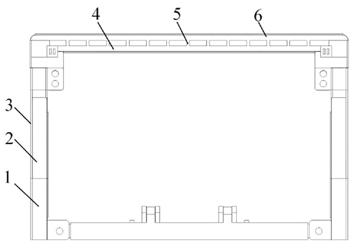
Schematic diagram of key variables: 1. Lower side shield body, 2. Upper side shield body, 3. Side guard panel, 4. Top beam frame, 5. Top beam frame reinforcement plate, and 6. Top plate protection.

Sensitivity diagram of key variables.
Response surface optimization
The response surface method is to obtain certain data sample points using a reasonable experimental design method and a multiple quadratic regression method to fit the relationship between the factors and response values and to seek the optimal variable parameters through the analysis of the regression equation.22,23 Response Surface optimization should first establish the test points. This study adopted the Optimal Space-Filling Design (OSF) method in the ANSYS Workbench Response Surface module to design test points with p1, p2, p4, p5, and p6 as design variables, and Standard Response Surface-full 2nd-order polygonal Algorithms were used to construct the response surface type. The constructed approximate response surface model needs to be verified to determine whether the model can be used as the basis for subsequent optimization. The analysis results of the response surface fitting index are shown in Figure 11. The output parameters of the rectangular shield temporary support device have a good fit with the response surface model, the fitting accuracy is high, and the convergence is good. Therefore, the response surface model obtained by the optimal space filling design method is accurate and available, and the model can be used as the basis for the next optimization design. The mass, displacement, and stress response surface models of the critical parameters were constructed as shown in Figure 12.

Response surface fitting index analysis diagram.

Mass, displacement, and stress response surface model diagram: (a) mass response surface model, (b) displacement response surface model, and (c) stress response surface model.
The weight of the equipment was taken as the optimization objective, the maximum stress was 98.6 MPa, and the maximum displacement was more significant than 0. Finally, the multi-objective Genetic Algorithm was used to screen and generate three groups of optimization data, which were rounded, as shown in Table 6.
Table of optimized key variable values.

After analyzing the results of the three groups, it was found that the third group’s weight, maximum displacement, and maximum stress were the best; therefore, the third group of parameters was selected to modify the model.
Modularization and lightweight matching of temporary support device of rectangular shield
Considering the different geological conditions and different requirements of roadway transportation and disassembly, a modular lightweight matching study was proposed for temporary shield support device. It is known that the geological environment of a mine is soft and complex, and it is easy to cause rib spalling and roof falling after roadway excavation. The total size (L × B × H) of the temporary support device of the rectangular shield was 4000 mm × 5400 mm × 3500 mm. Owing to the narrow working spaces of underground coal mines, it is difficult for large equipment or parts to be transported, assembled, and maintained underground. The volume and mass of the temporary rectangular shield support device were optimized according to the underground roadway environment and equipment structure characteristics. Three optimal matching schemes were proposed based on different focus indices. This study adopted the matching degree of modularization and lightweight to evaluate the rationality of the matching scheme.

where r is the matching degree; the closer the value is to 1, the more reasonable the scheme is, qi is the score of the ith matching index 0 < qi < 1, ki is the weight coefficient of the ith matching index, and n is the number of matching indices.
The complexity of the coal mine environment restricts the use of various transportation and assembly tools; therefore, the modular lightweight matching index mainly consists of the ⓐ transportability, ⓑ dismountability,ⓒ maintainability of modules, and ⓓ reliability of each module after matching. In the first scheme, the lower side shield body, upper side shield body, and roof shield modules are divided into two parts, which have good reliability because of the small number of structural module divisions and overall integrity. However, the size of each module is still significant after division, and thus, transportability is weak. In the second scheme, the lower-side shield body, upper-side shield body, and roof shield module are divided into three parts that have good transportation and strong reliability. In the third scheme, the lower side shield body, upper side shield body, and roof shield module are divided into four parts, which have good assembly performance, but their reliability is weaker than that of the other schemes because of the many structural modules. Considering the overall size and transportability of the device, further refinement of the device will increase the manufacturing cost and reduce the reliability of the device; therefore, this study only evaluates and chooses the three schemes, and the part materials in each scheme are Q345 steel. Each matching index in each scheme was scored, with 0 representing rejection and 1 representing the ideal index. The analytic hierarchy process is used to calculate the weight of each index, and mining equipment should have strong reliability and strong transportability, using the 1–9 importance scale to construct the evaluation matrix, as shown in the following formula:

The root means the square method is used to solve each index vector and perform normalization processing. The maximum characteristic root of the judgment matrix is calculated to obtain the consistency index of the judgment matrix and check whether the calculated results pass the consistency test.

where aij is an element in the judgment matrix, n is the order of the judgment matrix, and w is the nth root of the product of the elements in the ith row of the judgment matrix.


where CI is the consistency index of the judgment matrix, λmax is the maximum characteristic root of the judgment matrix, CR is the consistency ratio, when CR < 0.1, the calculation results are considered to have satisfactory consistency, through the consistency test, RI is a random consistency index, and the specific parameters are shown in Table 7.
Random consistency indicators.

The calculated results passed the consistency test and the weights of each index were set to 0.28, 0.16, 0.16, and 0.4, respectively. The matching degree analyses of different schemes are presented in Table 8.
Matching degree of module lightweight scheme.
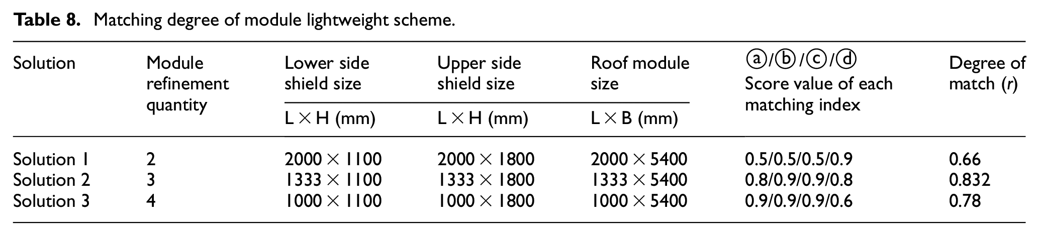
It can be known that the matching degree of the second analysis scheme is the best; therefore, the lower side shield body, the upper side shield body, and the roof shield module are refined into three parts to achieving the lightweight optimization goal of the equipment.
Reliability analysis of the optimized model
Structural characteristics analysis of the optimization model
The structural optimization model of a temporary support device with a rectangular shield was modified and imported into ANSYS Workbench finite element software. The material was Q345 steel, the mesh size was set to 50 mm, constraints and loads were imposed, and the roof shield body bear 800 kN and the base bear 50 kN. The calculation results are shown in Figure 13. The structural characteristics of the displacement and stress analyses satisfy the design requirements.
Nephogram of stress-displacement: (a) displacement nephogram and (b) stress nephogram.
After the shield body bears the uniform load, the stress model can be simplified as simply supported beam model, and the displacement of the device is primarily concentrated in the middle of the roof shield. In practice, because the material layout in area b of the device is located at the rear end of the device, the material layout is asymmetrical before and after the device. Therefore, under the influence of the uniform load in area c and the material layout in area a and area b, the maximum displacement is located at the front end of the roof shield.
The stress is mainly concentrated in the middle and two ends of the roof shield, and the maximum stress is located at the transition joint between the lower side of the roof shield and the frame. The reason is that after the optimized design of the device, the material layout and the size of key components change, but the stress model is still a simply supported beam model. In practice, due to the asymmetry of material layout before and after the device, the maximum stress position is located at the front end of the device under the influence of uniform load in area c and material layout in area a and area b.
By comparing the results of the weight displacement and stress before and after optimization, as shown in Table 9, it can be concluded that the weight of the temporary support device with the rectangular shield was reduced by 11.2% and the maximum displacement was increased by 9.8%, but it was still within a reasonable range, and the maximum stress was reduced by 13.4%, which is far less than the safe yield limit.
Comparison table of results before and after optimization.

Assembly process analysis
In different geological environment of coal mine, the size of the installation chamber can be excavated is also different. The geological condition is better, the roadway is not easy to rib spall and roof fall environment, the installation chamber size has greater flexibility; The geology is soft, the conditions are complex, the roadway is easy to appear the environment of the rib spall and the roof fall, the size of the installation chamber is strict. Therefore, reasonable and effective assembly process design is essential to avoid installation errors or positioning difficulties caused by unreasonable installation design. Based on the structural design characteristics of the shield temporary support device and the consideration of assembly time and space, aiming at the smallest installation chamber, this study designed the installation scheme as shown in Figure 14.

Assembly sequence diagram of temporary support device: (a) solution 1 and (b) solution 2.
In the first scheme, the assembly process of the guide column and shield body was critical. The guide groove on the lower side of the shield body was designed as a side opening. During the assembly, the guide column and upper side shield body were fitted and installed first, and then lifted by the crane and placed into the guide groove from the side. A baffle plate was installed, and the bolts were fastened to complete the assembly. It is suitable for poor geological conditions and limited use of large auxiliary transport assembly tools, which requires higher operation in the assembly process.
In the second scheme, the assembly process completes the shield assembly according to a bottom-up installation sequence, It is suitable for good geological conditions and large auxiliary transport assembly tools can be used, and the assembly process is operable. Modules based on modular lightweight fusion and matching are more convenient for transport and assembly. The required installation roadway size is smaller, thus reducing the difficulty of work. The comparison of the assembly process methods are listed in Table 10.
Assembly process comparison table.

Conclusions
In this paper, the lightweight design of the temporary support device of rectangular shield for the robot system of coal mine roadway excavation was completed. The specific conclusions are as follows:
The modular design concept was applied to the structural optimization of the temporary support device of a coal mine shield, and a modular division method combining the functional analysis method with a similar feature clustering method was proposed. The modular division of the temporary shield support device was completed, and a modular three-dimensional model was established.
The structural optimization method of “variable density topology optimization, parameter sensitivity analysis, and optimal space-filling design (OSF)” was proposed, and the lightweight design of the temporary support device of the rectangular shield was completed. The initial lightweight design of the device was achieved using a variable-density topology optimization method. The key variables of the device were screened using the parameter sensitivity analysis method, and sample points of the device were generated using the optimal space-filling design. Response surface models of the mass, displacement, and stress were constructed, and the optimal solution for the device weight was obtained under the constraint conditions of pressure and displacement.
A modular and lightweight fusion-matching method based on transportability, dismountability, maintainability, and reliability was proposed, and the bulk structure optimization of the rectangular shield temporary support device was completed. The feasibility of the fusion-matching scheme was determined by the matching degree, and an optimal matching scheme was selected. A comprehensive analysis of the optimized device model shows that after lightweight optimization, the temporary shield support device has a reliable structure; the weight is reduced by 11.2%, and the maximum stress is decreased by 13.4%, which realizes the optimal design of a lightweight temporary support device.
Footnotes
Handling Editor: Chenhui Liang
Declaration of conflicting interests
The author(s) declared no potential conflicts of interest with respect to the research, authorship, and/or publication of this article.
Funding
The author(s) disclosed receipt of the following financial support for the research, authorship, and/or publication of this article: This research was supported by the Intelligent Detection and Control Innovation Team of Coal Mine Electromechanical Equipment (Grant No. 2018TD-032), Project of the Shaanxi Provincial Department of Education (Grant No. 22JC051) and Project of Science and Technology Department of Shaanxi Province (Grant No. 2023-JC-YB-331).