
Abstract
This paper presents an energy and perception aware framework for path planning and navigation of unmanned aerial vehicles (UAVs) in GNSS-denied and spatiotemporal wind environments. The proposed framework mainly consists of the global and local path planning methods that respectively consider the energy consumption of an UAV and perception quality of a light detection and ranging (LiDAR) sensor mounted on the UAV. The energy consumption is estimated based on the aerodynamic model that calculates drag and lift forces on the UAV. The global planner then uses the total energy consumption in the spatiotemporal wind as the cost function to find an energy-efficient path as a set of waypoints. The local path planning navigates the UAV between the waypoints with maintaining the perception quality. The perception quality is quantified based on how well the LiDAR sensor scans feature points around the UAV that highly correlates with the navigation accuracy. Numerical simulation study for each of the global and local path planners validates their usefulness. Further, the overall framework is entirely verified in a long-range flight scenario of the photorealistic environments developed in the Gazebo simulation.
Introduction
Autonomous unmanned aerial vehicles (UAVs) have been widely used for various missions such as construction/infrastructure inspection and search and rescue in disaster environments. In these missions, UAVs are often limited in their flight distance/duration because of obstacle collisions, the shortage of onboard batteries, or positioning errors owing to onboard sensors and loss of signal from global navigation satellite system (GNSS).
Collision avoidance is the essential and fundamental for UAV’s motion planning. Currently, several collision avoidance approaches have been reported 1 and validated for their usefulness in actual UAV flying situations.
On the other hand, for the battery problem, UAVs should basically be as light as possible while multiple battery packs should be mounted on the UAV for long-range flight, increasing the weight of the UAV. The trade-off between the UAV weight and its batteries severely limits the flight time and range. Additionally, the increase in aerodynamic drag due to the wind effect has a significant impact on the energy consumption of UAVs.
Recent studies have proposed UAVs’ flight planning methods to reduce the energy consumption of UAVs owing to weather changes 2 or using battery consumption models. 3 Miller et al. 4 proposed the cost-optimal path planning that solves time and risk constraints for UAVs in 3D space. This planner, however, is computationally more expensive than grid-based algorithms such as A*. 5 Otte et al. extended the anytime A* algorithm, enabling UAVs to fly time-efficiently and avoid dynamic obstacles in real-time. 6 Although there have been several studies on path planning methods that reduce the energy consumption of UAVs, none have focused on global path planners in a 3D environment where wind varies in time and space.
GNSS-denied environments/conditions often seen in stormy mountainous areas, forests, and even urban canyons requires UAVs to reliably fly autonomously. Simultaneous localization and mapping (SLAM) is capable of self-pose estimation as they utilize onboard vision sensors such as cameras and light detection and ranging (LiDAR).
Numerous studies have developed the local planning and localization methods to reduce the state estimation error for UAVs in GNSS-denied environments. Camera-based pose estimation enables UAVs to reach user-specified goals with a certain level of accuracy.7,8 However, it has severe limitations; for instance, the pose estimation does not perform well in non-landmark or texture-less areas. Most studies have shown that the accuracy of pose estimation can be improved by perception-aware paths where the camera’s field of view captures effective feature points for SLAM or visual odometry algorithms.9–12
Another technique for UAVs’ pose estimation is the use of a LiDAR sensor, that directly measures three-dimensional distances from the sensor to the objects with a 360° field of view.13,14 Currently, LiDAR-based SLAM algorithms (Figure 1) have been proposed to improve the accuracy of pose estimation.15–17 However, similar to camera-based pose estimation, LiDAR-based SLAM suffers from geometric degeneration such as long straight tunnels and planar environments, where there are few valid feature points. The camera-based perception-aware path plannings9–12 can not directly be exploited to the LiDAR-based SLAM system. This is because the feature points measured by LiDAR are more numerous than those captured by a camera, and are distributed 360° around UAVs. A few studies have addressed the degeneration problem for the LiDAR-based SLAM.18–21 To solve the optimization problem for pose estimation, Zhang et al. only used well-conditioned constraints, and Jiao et al. selected valuable/informative features. Zhou et al. exploited the Fisher information matrix (FIM) associated with the LiDAR measurement uncertainty, detecting the degeneration degree of the sensor measurements. Zhang et al. 22 proposed the perception-aware path planning method to address such degeneration problem. They introduced the idea of the Fisher information field (FIF) to efficiently calculate the FIM from a set of sparse point cloud. While the planner with FIF increases the localization success rate and accuracy, it is limited in known environment since the accurate pre-computation of the FIF is needed.

Example of LiDAR-based SLAM using 3D LiDAR mounted on the UAV. The 3D LiDAR provides a 360° field of view as point cloud (small colored dots). The SLAM algorithm extracts feature points (large blue dots) from the scanned point cloud, generates a global map (white dots), and estimates the pose of the UAV (yellow line).
Thus, autonomous navigation techniques presented in the existing studies may not be able to sufficiently drive UAVs in GNSS-denied and spatiotemporal wind environments. Therefore, this paper addresses an energy and perception aware framework for planning and navigation for UAVs, enabling the UAVs to fly a path with maintaining the energy efficiency and pose estimation accuracy. The proposed framework is elaborated by combining our previous works in Aoki and Ishigami 23 and Takemura and Ishigami 24 for achieving global and local path planning. As in the literatures,25,26 it is common for local and global planners to solve different problems and to integrate them well. The global path planning algorithm quantifies the energy consumption of a UAV in spatiotemporal wind environment and finds an energy-efficient path. 23 The local path planner assesses the perception quality for a LiDAR-based SLAM algorithm online, enabling robust autonomous flight in GNSS-denied unknown environments. 24 This paper incorporates these global and local planners and elaborates a planning and navigation framework that can drive a UAV to fly along an energy-efficient and SLAM-reliable path. Our research highlights in this paper are as follows:
the integration of the energy efficient global path planner and perception-aware local path planner for a UAV,
the parameter study of the perception-aware path planner,
the validation of the energy-efficient path planner using a high-fidelity simulator, and
the verification of the proposed framework in GNSS-denied environments and spatiotemporal wind using photorealistic simulations.
The remainder of this paper is organized as follows: the second section defines the problem statement; the third section shows an overview of the proposed framework; the fourth section explains the energy-aware global path planning; the fifth section proposes the perception-aware local path planner; the sixth section discusses the results of our numerical simulation; and, finally, the seventh section draws the conclusion and presents a direction for the future studies.
Problem statement
We assume that a UAV is equipped with a 3D LiDAR sensor on its bottom, enabling 3D scanning with a 360° field of view (Figure 1). Further, a global goal is given by human operators before the UAV starts to fly. The UAV does not always see the goal; therefore, the global path planner generates a waypoint set based on a global map. While flying toward each waypoint, the UAV measures environments and generates a local map at constant intervals.
This research aims to ensure that the UAV reaches a given global goal in GNSS-denied and spatiotemporal wind environments while reducing the energy consumption and pose estimation error. We address this challenge as global and local path planning problems. We assume that the global map only includes the spatiotemporal wind information, which can be accurately predicted based on the weather and climate forecast data 27 prior to the UAV’s flies. On the other hand, the detail 3D environmental information, which is acquired by onboard sensors, is subject to uncertainty until the UAV actually flies. For instance, in disaster areas, the destructed buildings are one of the uncertain information. Hence, we exploit the wind information in the global planning and use the 3D geometrical information in the local planning. The global path planning finds an energy-efficient waypoint set based on the spatiotemporal wind map. As for the local planning phase, smooth and collision-free paths toward each waypoint are generated while maintaining the perception quality in the 3D local map. Owing to the limitation of the LiDAR’s scanning range, the local planning is conducted based on the current pose and local map at each step, that is, the problem is solved in a receding horizon manner as in Tang et al. 28
System overview
Figure 2 illustrates an overview of the proposed navigation system, which mainly consists of offline and online processes. In the offline phase, the global path planner, which is one of the core components of our research, finds the waypoint set to steer the UAV from the start point to the goal area. The planner explicitly considers spatiotemporal wind speed based on a global map. The wind data is exploited to estimate the energy consumption of the UAV. The estimated energy is defined as the cost function in the global planner, which enables the UAV to find an energy-efficient global path. The path is generated by the extended A* algorithm 5 that exploits a variable-resolution grid approach as in adaptive Single Time-step Search (aSTS). 29

Schematic overview of autonomous navigation systems for UAVs.
The online process consists of a LiDAR-based SLAM, local path planner, and classical PD controller. For the LiDAR-based SLAM algorithm, advanced implementation of LiDAR odometry and mapping (A-LOAM)
30
was used to provide pose estimation and mapping for the UAV. A-LOAM processes the point cloud data acquired by 3D LiDARs
31
; and, extracts feature points
Energy-aware global planner
The proposed global planner exploits the aSTS method to account for the energy consumption of the UAV in an environment where wind velocity varies temporally and spatially. The aSTS is a graph-search-based method, which adaptively changes the resolution of the grid that divides the state space. Therefore, the method enables autonomous marine vehicles to generate energy optimal paths that match the realistic effect of 2D temporally and spatially varying flows. In our planner, the conventional aSTS method is extended by constructing a 3D graph in the path planning process, enabling the generation of 3D paths. Further, the proposed algorithm constructs a search graph based on the spatiotemporal wind map predicted by the wind speed dataset. The algorithm solves the path planning problem by calculating the cost between each node based on the UAVs’ energy consumption model.
Cost and heuristic functions
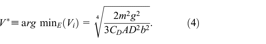
The cost function of the node

where
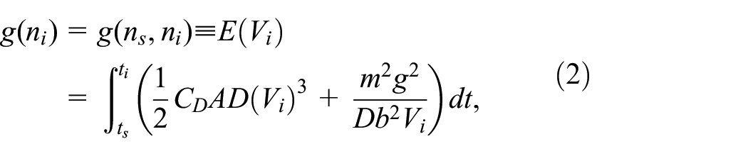
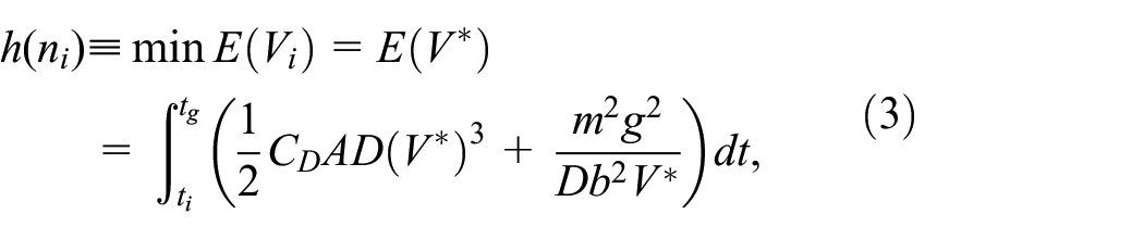
where
Variable-resolution grid
In this study, the aSTS method is extended by varying the grid resolution based on the following equations:


where
In the aSTS method, Newton’s method calculates the upper bounds of spatial resolution
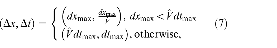
where

Equation (8) avoids a large mismatch between the spatial resolution and the resolution of the wind speed data. Basically, the wind data is discretely given; and hence, the wind speed at each node is interpolated. When the resolution of the wind map is too discrete, and
Search graph structure
In the proposed global planner, the graph for the A* algorithm is iteratively constructed based on a hypersphere with radius

Graph construction based on a hypersphere and inscribed regular dodecahedron.

Search algorithm
The procedure of the proposed global planner is shown in Alg. 1. The algorithm begins the loop procedure (Line 2). As the first step of the loop, the cost-minimum node


where


Auxiliary illustration for the proposed global planner: (a) relationship between target velocity, wind velocity, and air speed in the xy plane. (b) How to calculate the bounds of the spatial and temporal resolutions.
where

Euations (9)–(12) are solved in conjunction. The function getMaxErrDir(-) calculates the direction with the largest wind velocity change around
Perception-aware local planner
Figure 5 illustrates the detailed diagram of the online process in Figure 2. The local path planning consists of a tree generation module based on RRT* and a path selection module. The planner exploits the RRT* algorithm to generate a library of candidate paths based on the current pose and map. The path selection module evaluates each path based on two metrics: the perception quality and goal progress. Based on the evaluation, the local path planning selects the best path to execute with the low-level controller. The path planning is iteratively conducted in a receding horizon manner until the UAV reaches the specified waypoint. For each planning step, the planner searches a path in a user-defined cubic area (Figure 6) based on the map and pose estimated by A-LOAM.

Schematic overview of online process.

Receding horizon path planning using the RRT* algorithm. The algorithm extends the tree (lines) and stores nodes (black circles) in the tree. In the proposed path planning, the branches of the tree are pruned (dotted lines) and a library of candidate paths
Tree generation
The RRT* algorithm, which can generate a cost-optimal and collision-free path, 33 was exploited as the tree generation module. In this study, RRT* extends the tree as a library of candidate paths. This approach is similar to, 28 where a UAV efficiently explored unknown areas. Given that the generated tree may not be smooth for the UAV’s tracking, dynamic models 11 or smoothing techniques35,36 are necessary. However, this point is not the core of our contribution and will be ignored here.
The procedures of the tree generation are summarized as follows:
1. Sample a random node (blue circle) from the user-defined cubic area (Figure 6(a)).
2. Obtain the parent node that minimizes the total distance from an initial node to the sampled node.
3. Extend the tree from the parent node (small red circle) to the sampled node (small blue circle) with a collision check (Figure 6(b)).
• If the distance between them is shorter than
• If the distance is larger than
4. Perform the node rewiring process as the conventional RRT* algorithm does.
5. Repeat the procedures 1–4 until the number of sampling a node reaches
6. Prune branches of the tree to have only
Eventually, we obtain a library of candidate paths
Path selection
The path selection module determines the final path

where
Reward for perception quality
Given candidate paths, the path selection module evaluates the perception quality based on the information about whether the feature points extracted in LiDAR-based SLAM can improve pose estimation accuracy. First, at each tip node of candidate paths, the path selection module chooses valid feature point that the UAV can see. We define the feature points scanned at a start node for every path planning as

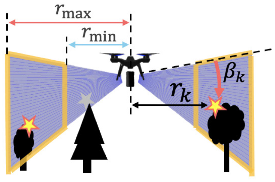
Reliable measurement range of the 3D LiDAR sensor. The LiDAR-based SLAM algorithm extracts feature points (stars). In the local planning, the points are separated into valid (yellow) or invalid (gray).
where
Subsequently, we introduce a circular grid graph as in Figure 8 to consider the perception quality using the valid feature points. The grid graph enables the planner to handle sparse point cloud set efficiently similar to the FIF. 22 The graph contains grids in radial and angular directions; and, each grid is true when it contains at least one valid feature point. The perception quality is calculated based on the number of true grids close to the UAV and the degrees of their scattering. The derivation of the circular grid is based on the following two core facts:
LiDAR measurement uncertainty decreases as the point cloud is scanned closer to the UAV, and
scattered feature points enable the LiDAR-based SLAM algorithm to decrease the localization error.

Circular grid graph for the perception quality calculation. A grid in the graph becomes true (orange) if it contains at least one valid feature point (yellow stars).
According to the work, 37 the LiDAR uncertainty is subject to an large error for distance measurement. Hence, the feature points close to the UAV may be robust to pose estimation for the SLAM algorithm. In addition, as reported in, 18 the features/constraints distributed in different directions, may avoid the degeneration of the SLAM algorithm. Certainly, based on the flight simulation in Figure 9, evenly-distributed feature points contribute to more accurate pose estimation than the feature points biased to one side as shown in Figure 10.

UAV flight simulation in Gazebo with the PX4 Software. The simulation was performed for several seconds along with the red arrows. Left and right figures show an environment with scattered and gathered obstacles, respectively.

Pose estimation error of the A-LOAM algorithm with respect to increasing traveling time.
Then, the reward related to the perception quality is defined as follows:
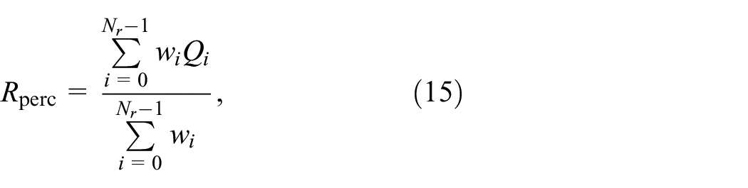
where


where

Note that we can calculate the FIM on each grid as in9,21,22; however, to account for the degree of scattering of feature points, we introduced equations (15)–(18).
An example of the reward is shown in Figure 11 and Table 1. Comparing Figure 11(a) and (b), we can observe that the reward

Examples of the calculation of
Examples of the reward for the perception quality.

Cost for goal progress
The cost function for goal progress expresses how close a path approaches a destination. First, we define the distance decrease to the goal as follows:

where
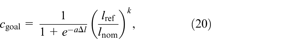
where

Cost function for goal progress when
Simulation study and discussion
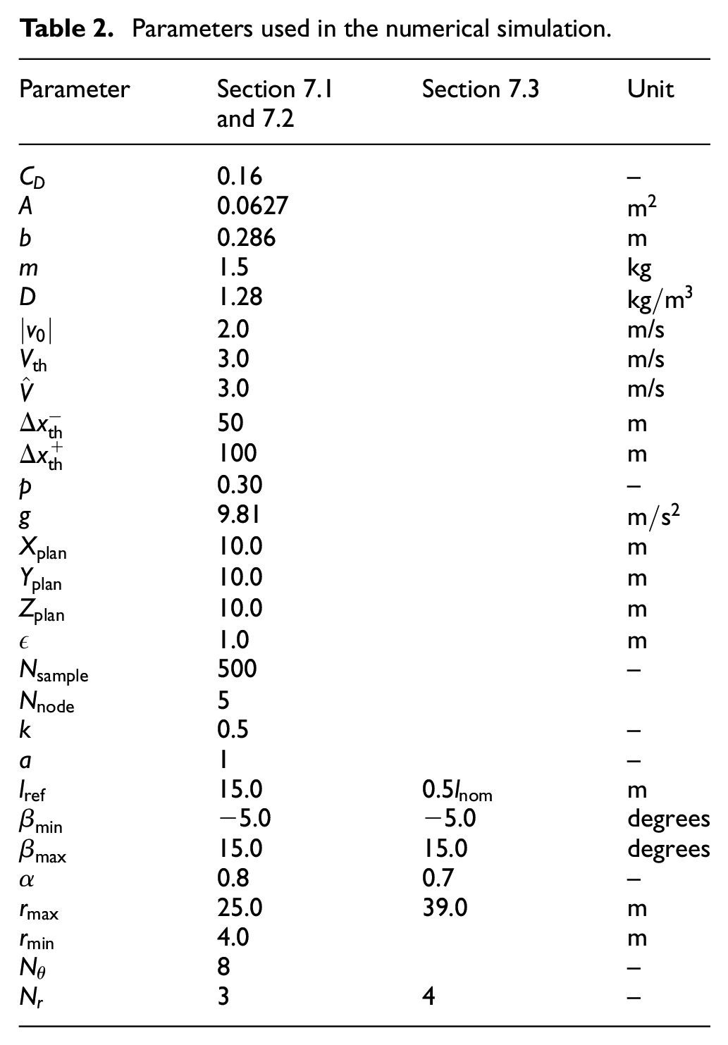
The offline and online processes in the proposed framework were implemented using MATLAB and the robot operating system, 38 respectively. An actual UAV in an experimental setup would be a promising approach for its demonstration; however, it is subject to the uncertainties in the sensing and control performance. Therefore, to verify the proposed framework, we prepared simulation environments in Gazebo supported with the PX4 software in the Loop simulation. 39 The UAV model is an extension of PX4 Vision, 40 replacing its camera with a 3D LiDAR (VLP-16) simulation model. 41 Table 2 summarizes the parameters used for the simulation.
Parameters used in the numerical simulation.
This section first shows the simulation result for the perception-aware local path planner. Subsequently, the result of the energy-aware global path planning is introduced. Finally, the practicality of the proposed framework is shown in a long-range flight scenario.
Local path planning result
According to the previous study,
9
we highlight the effect of the proposed local planner through a comparison with a purely-reactive path planner (
We evaluated each planner using two metrics: final position error and flight success rate. The final position error was calculated based on the result of A-LOAM and a true value obtained from the Gazebo simulator. The error was averaged without any obstacle collision and large position error (of more than 15 m). The success rate indicates that the UAV can fly the planned path without the flight failure.
The simulation results are summarized in Table 3. The flown path and time history of the position error are also shown in Figures 13 and 14. For simplicity, only three flight paths are depicted in the figures.
Results of final position error and flight success rate.


Results of Gazebo simulation for Scenario 1–4. Flown paths overlaid on the top view of the environment. The results of the proposed planner (blue) and a purely-reactive path planner (red) are depicted. We illustrate the start and goal areas as yellow and orange circles, respectively: (a) Scenario 1, (b) Scenario 2, (c) Scenario 3, and (d) Scenario 4.
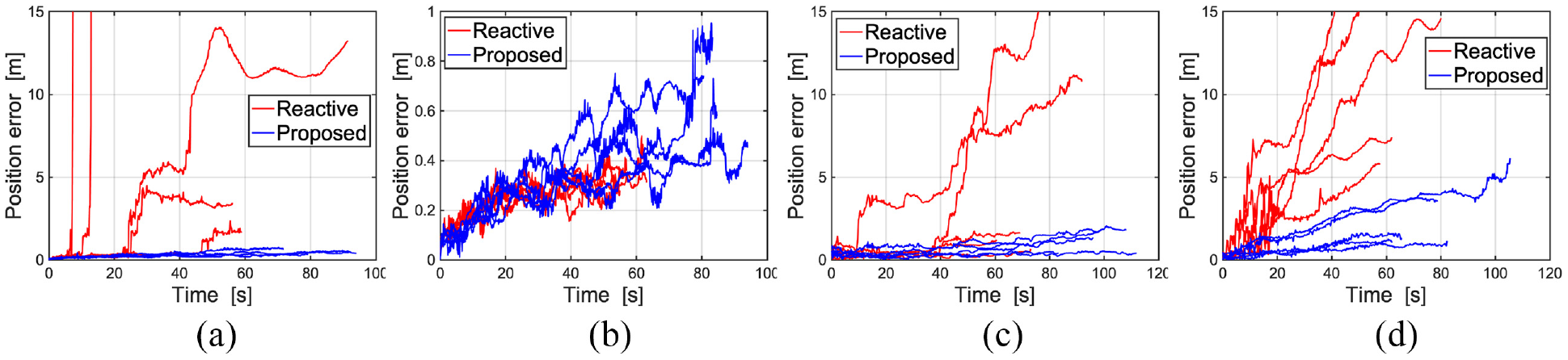
Time history of the position error in Scenario 1–4: (a) Scenario 1, (b) Scenario 2, (c) Scenario 3, and (d) Scenario 4.
Scenarios 1 and 2 were the identical environments; however, we specified different goals for each scenario. In Scenario 1, the goal was specified beyond the objectless area in the upper part of the environment. While the UAV with the purely-reactive path planner attempted to move directly to the destination, our proposed planner encouraged the UAV to approach the obstacle-rich area. This implies that the proposed planner let the UAV to scan many feature points throughout the flight as equation (13) satisfies. Therefore, we observed the remarkable improvement of the position error as shown in Table 3.
In Scenario 2, the purely-reactive planner was also able to generate paths without the loss of pose estimation accuracy. Based on the result of the position error, it outperformed the proposed path planner. This is because the proposed planner encouraged the UAV to fly in the obstacle-rich area, resulting in a long flight distance. Essentially, the position error in the SLAM algorithm grows cumulatively as the flight distance increases. This point can be improved by dynamically tuning
Scenario 3 consisted of an uneven mountainous terrain and riverside in the upper and middle parts of the environment, respectively. Although the purely-reactive planner successfully completed almost every flight, two trials of the simulation resulted in poor performance: one failed and the other caused a large position error. Conversely, the proposed planner steered the UAV to move along the riverside as shown in Figure 13(c), maintaining a small position error throughout the flight. We deduce that this is because the UAV can preferentially scan the mountainous area, where feature points are rich, rather than the riverside.
Scenario 4 consisted of the foot of a mountainous area with a flat texture-less area. The purely-reactive path planner failed in three trials of the simulation and the position error even in the successful cases was large. The proposed planner encouraged the UAV to fly along the foot of the mountain and succeeded in all trials. This result implies that the perception quality can be evaluated so that the accuracy of the pose estimation can be maintained even if the feature points are biased in a certain direction.
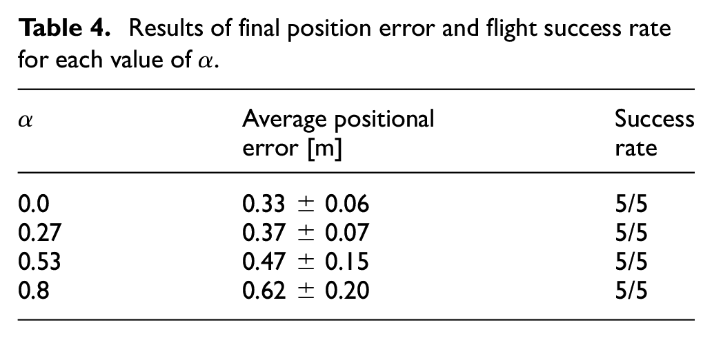
To verify the performance of the weighting factor, we tune
Results of final position error and flight success rate for each value of

Result of Gazebo simulation for parameter tuning in Scenario 2. Flown paths overlaid on the top view of the environment. The results of
Overall, the simulation results confirmed the performance of the proposed local path planning. The planner was able to fly the UAV with an 73% higher accuracy than the purely-reactive planner on average, except for Scenario 2. In every scenario, the UAV was able to reach the destination without any flight failures. Further, the parameter tuning can improve the performance of the local planning, resulting in the reduction of flight time and distance.
Global path planning result
For the global planning, we generated the wind map based on the deterministic method used by Mollov et al. 43 The spatiotemporal wind speed is modeled as follows:

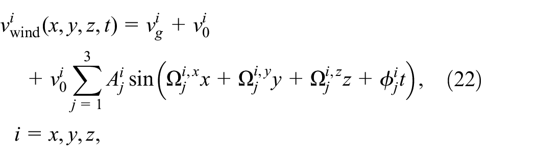

where

where
The global path planning results are shown in Figure 16(a) to (c). The energy consumption and flight time of the energy-aware path are also summarized in Table 5. The table also includes the result of the direct path, where the UAV directly flies from the start to the goal. As shown in Figure 16(a), we observed that the path is generated along the wind vector, resulting in the minimum values of the energy consumption and flight time among three cases. On the other hand, the UAV cannot fly along the wind vector in the upward and sideways scenarios. In the upward wind data, the proposed planner generated a nearly direct path to the goal area, enabling the UAV to reduce flight time and energy consumption. This can be confirmed through a comparison of the flight time of the proposed and direct paths. For the sideways wind, the vector from the start to the goal is in the opposite direction of the wind vector. Hence, the planned path deviates from the headwind and detours the area around

Results of the global path planning in three types of wind: (a) downward wind, (b) upward wind, and (c) sideways wind.
Estimated energy consumption and flight time for the proposed and direct paths.

While the usefulness of the energy-efficient global planner is shown in the previous work, 23 this paper verifies the planner using the high-fidelity simulator. The Gazebo simulation framework was employed again to evaluate the global path in the sideways wind, which is the most critical scenario among the three types of wind environments. The wind plugin was exploited to express the wind effect in the Gazebo simulator. The UAV directly tracked each waypoint at 3.0 m/s. The energy consumption was calculated based on the thrust force of four motors of the UAV. 44 Each thrust was measured by the Gazebo force sensor plugin. 45 Table 6 shows the result of the simulation.
Result of the verification test in the sideways wind.
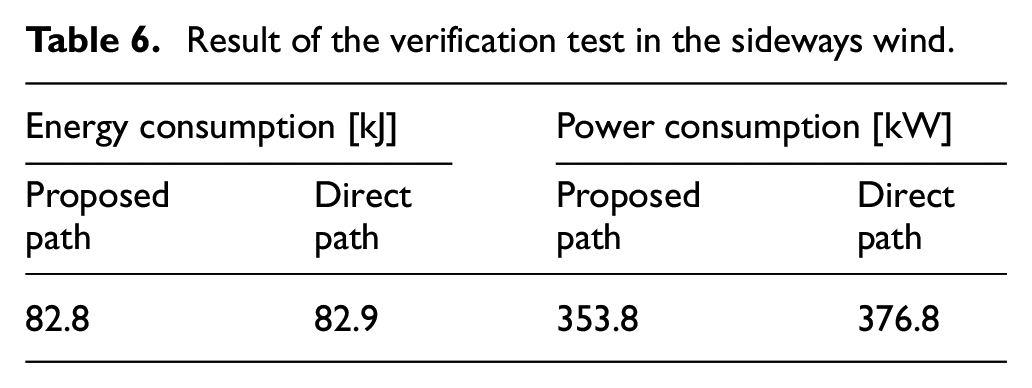
We can observe only a slight reduction of the energy consumption as compared with the improvement of Table 5. We deduce that this is because equation (2) does not accurately estimate the energy consumption in UAV’s actual motions. For instance, the proposed path required the UAV to turn around
Long-range flight demonstration
This subsection demonstrates the practicality of the local and global path planners in a long-range flight scenario. The simulation assumes the mountainous area and the sideways wind scenario. The UAV flies toward each waypoint generated by the energy-aware global planner (Figure 16(c)). The perception-aware local planner sequentially performed for each waypoint. However, during the flight simulation, each waypoint was relocated to avoid the area where the SLAM algorithm fails. Intuitively, the SLAM algorithm would work well when the onboard LiDAR can adequately scan and cover terrain surfaces. For that, we controlled the altitude of the waypoints upward and downward. The planned and modified waypoint sets are shown in Figure 17. The local planner generated the local path toward the modified waypoints (red circles) in the figure. Figure 18 and Table 7 show the result of the simulation.

Relationship between the modified waypoint set and the global path planning result. The start point is (600, 600, 190) and the goal point is (200, 200, 60).

Result of Gazebo simulation for a long-range flight scenario. Flown paths overlaid on the top view of the environment. We illustrate the start and goal areas as yellow and red pinpoints, respectively.
Results of Gazebo simulation in a long-range flight scenario.

We can observe that the proposed navigation framework enables the UAV to reach the global goal without flight failure. The simulation result verified that the local path planner sequentially works well. According to Table 7, however, the energy consumption is six times larger than that of Table 6. We deduce that this is because the UAV flew along the perception-aware local paths, thus increasing the flight distance and time. The UAV intended to deviate from the straight path between two waypoints to maintain the perception quality without large positional errors. Comparing the global planning and Gazebo simulation results, the difference between the actual and expected flight time is about 1000 s. The trade-off of perception-awareness and flight distance would be improved by tuning
We tune the weighting factor

Energy consumption for each value of the weighting factor
Conclusion
In this study, we have presented the energy and perception aware planning and navigation framework for UAVs in GNSS-denied environments and spatiotemporal wind. The proposed framework integrates the energy efficient global path planner with the perception-aware local path planner. We validated the local and global planners in the simulation study. The proposed local planning performed the improvement of pose estimation accuracy, except for Scenario 2. The parameter study showed the weighting factor for the perception quality can be adjust for each environment, which leads to optimize the pose accuracy and flight time. The global path planner generated the energy efficient waypoint set, which can be along the wind vector and deviate from the headwind. The high-fidelity simulator with the wind plugin validated that the global planner performed well even in the critical environment. Finally, the overall framework was entirely verified in a long-range flight scenario, where the local path planner sequentially worked well without flight failure. Additionally, we found that the sensitive parameter for our framework, which is not only critical for the perception quality, but also for the energy consumption. Once the parameter is preferably adjusted according to each flight environment (i.e. lower
Future work would include the automation of the parameter tuning. A possible solution is a machine learning approach, which models the relationship between the optimal
The extension of the global planner is also of interest so that the LiDAR can scan feature-rich area. Although the 3D environmental information cannot be obtained prior to the UAV’s flight, the global map can be updated based on the feedback information from the online control. The global path is then replanned using the updated map with 3D geometrical information, allowing the UAV to approach more perceptible areas. This would improve our poor way to relocate waypoint set for the local path planner.
Footnotes
Handling Editor: Chenhui Liang
Declaration of conflicting interests
The author(s) declared no potential conflicts of interest with respect to the research, authorship, and/or publication of this article.
Funding
The author(s) received no financial support for the research, authorship, and/or publication of this article.