
Abstract
Wear has serious influence on the strength and tightness of tubing joint. In this paper, a new joint wear establishment method, “numerical cutting method,” was proposed and the stress distribution characteristics of sealing surface were analyzed. The three-dimensional modeling of a worn tubing joint under complex loads was successfully established and the finite element method was used to calculate the stress distribution on sealing surface. The influence of internal wear on the stress distribution of the sealing surface was analyzed and the failure mechanism of a worn tubing joint was revealed. The results showed that the contact stress of the worn part of the sealing surface decreases with increased wear depth of internal wear. When the internal wear depth reaches 3.0 mm, the maximum contact stress in the worn area decreases by 35.5% than that of the unworn joint along the axial direction and by 27.3% along the circumferential direction of sealing surface. While when the external wear reaches 3.0 mm, the stress distribution of the sealing surface is similar to that of the unworn joint. These mean that more attention should be paid to the prevention of internal wear during operation because an internal wear has more effect on the stress characteristics of the sealing surface than external wear. The sealing belt is located in the middle of the sealing surface, and the width of the sealing belt at different wear depths is roughly the same for two wear forms. This is beneficial to ensure the seal integrity of tubing joint.
Introduction
Around the world, there are many wells that were ultra-deep and with ultra-high temperature and ultra-high pressure. During operation, the temperature at the bottom of the well can exceed 300°C; during the acid fracturing process, bottomhole pressure can exceed more than 200 MPa. One of the major issues facing these wells was wellbore integrity failure. The frequent downhole tool failures have caused great economic losses and brought serious safety risks. The main indicators of wellbore integrity destruction are tubular deformation and high annular pressure at the wellhead. 1 In the oil and gas production, the annular pressure caused by seal failure has been a very difficult and dangerous problem to solve. Many researchers have done a lot of work in this area and achieved remarkable achievements.2–4 But they have paid more attention to the integrity of the second sealing barrier formed by packer, string and wellhead device, as shown in Figure 1, and less attention to the sealing of tubing and casing joints, let alone the tightness of the worn joints.

Well system.
The oil tubing string consists of a number of single tubing approximately 9 m in length connected by threaded joints. This makes the joint potentially the weakest part of the entire string. The statistics showed that 64% of tubing and casing failures occurred in joints, and as much as 86% in some oilfields. 5 In recent years, the use of premium joints has significantly improved the safety of joints compared to API standards joints, but in practice, most string failures were still caused by leaky seals at connections. 6 In order to study the reason of sealing failure, many scholars have used a variety of methods to analyze the mechanical properties of the sealing surface of the premium joint and have made great improvement.
Chen et al. 7 and Xu et al. 8 used analytical method to explore the influence of geometric features on strength and sealing performance of pipe string. However, the analytical solutions were based on some assumptions, which couldn’t take into account the multiple nonlinearities involved in the operation of joints of pipe with complex structures.
In the studies by Wang et al., 9 Zeng et al., 10 and Jingyu and Qi, 11 the experimental method was used to reflect the change of sealing performance of the joint applied with loads. However, due to the complex meshing structure of pin and box, it is difficult to directly measure the strain of the sealing surface. In addition, the experimental method has the characteristics of high cost, long test cycle, and high risk. In particular, some actual complex loads are difficult to apply.
In view of the shortcomings of the above two methods, numerical simulation was used more and more to carry out related studies. Among them, finite element method has been widely used. Ishimura et al., 12 Hilbert and Bergstrom, 13 DeLange et al., 14 Chen et al., 15 and Chen et al. 16 have done successful studies on sealing performance of joints by finite element method.
What needs to be pointed out is that the current research on the mechanical characteristics of the sealing surface was mainly carried out for the unworn joint. However, under the actual working conditions, there were seriously wear at the tubing joints, and it was found that 44.7% of the wells were lost due to tubing thread during production safety inspection. 17 The tubing is subjected to alternating loads thousands of times a day, and as the weak part of the tubing string, the integrity of joint is easy to damage due to plastic deformation caused by degradation of performance due to wear. Therefore, it is very important to pay attention to the influence of wear on its sealing performance.
In this study, a “numerical cutting method” was proposed to establish worn tubing joint model in case of internal and external wear. Then the stress characteristics of sealing surface were studied by the finite element method. The results could provide useful support for the research on sealing integrity of oil tubing string in ultra-deep wells.
Geometric characteristics and parameters of premium joint of tubing
Ultra-deep wells that have ultra-high temperature and pressure have higher requirements on the tightness, strength, and corrosion resistance of tubing joints. Among all the premium joint products, the partial trapezoidal joint has been widely used, and its sealing performance can be improved by changing structural parameters. For example, the design of the auxiliary sealing surface of torque shoulder can improve the sealing performance, enhance the anti-compressive strength of the joint. 18 Figure 2 shows the structural diagram of a typical premium joint used in the TLM oilfield, China. Its main sealing structure is metal-metal sealing mode, including three structural forms of cylinder-cylinder, cylinder-sphere and sphere-sphere, which can ensure the maximum contact pressure of the joint remains unchanged under tensile condition. At the same time, a negative 15° reverse torque shoulder was designed to make the connection have better sealing performance, as well as anti-compression and anti-over-torque performance.19–21

Structure of a typical kind of premium joint used in TLM oilfield: (a) thread tooth structure and (b) sealing structure.
A three 1/2″ tubing joint with above structure was analyzed to show the influence of internal wear on the sealing performance of the premium joint. The outer diameter R0, the inner diameter R, and the outer diameter of coupling R′ are 88.9, 76.0, and 114.3 mm respectively. The detailed thread parameters and corresponding crew thread parameters are shown in Table 1.
Main geometric parameters of premium joint of oil tubing.

Finite element model of tubing joint
This study selected ABAQUS to analyze the three-dimensional mechanical properties of the sealing surface of the tubing premium joint. In the process of solution, a new stiffness matrix appears in each increment step. This makes the implicit algorithm more complicated than the explicit one because it requires a lot of matrix inversion calculations, which lead the explicit algorithm be selected for calculation.
Three-dimensional finite element model for tubing premium joint
Figure 3 lists the three-dimensional geometric model for three 1/2″ tubing premium joint. The eight-node hexahedral element was selected to mesh the model. The number of element and node in the finite element model of premium joint for an unworn tubing were 280,824 and 344,277 respectively. The loads were applied by establishing the coupling form of distributing nodes on the end face of the pin, and the constraint was imposed by establishing the coupling form of kinematical node at the end face of the box (as shown in Figure 4).

Geometric model of premium joint of tubing.

Meshing and boundary conditions of tubing joint.
Three-dimensional finite element model for the worn tubing premium joint based on “numerical cutting method”
In engineering practice, the failure of tubing connection is a problem that has not been solved for a long time. One of the reasons is that the study of the three-dimensional mechanical characteristics is rare for the sealing surface of worn joint of tubing. According to the field experience, there are two main forms of tubing wear: external wear and internal wear. External wear mainly appears in the outer wall of the tubing, caused by friction between the outer wall of the tubing and the inner wall of the casing, while internal wear mainly appears in the inner wall of the tubing, caused by friction between the sucker rod and the inner wall of the tubing.
The current research on the construction of worn joint model usually uses the method of wear first, then load. However, in actual working conditions, there is a causal relationship between load and wear, and the first wear may affect the calculation result because it has changed the structure of the joint already. Therefore, in this article, the numerical cutting method is used to building the wear joint model, which is more close to the actual situation of the joint.
Establishment of worn joint model
In order to establish a worn tubing modeling, a “numerical cutting method” was proposed based on an unworn tubing modeling. As shown in Figure 5, a worn premium joint model of tubing is listed. The red part in the figure is the wear layer, which consists of five layers of grid, and the maximum wear depth of each layer is 0.6 mm. Five “cut blades” were set up, as shown in yellow part. One “cut blade” represents a part of the drill pipe contour and corresponds to a wear layer, and the blades and the corresponding wear layer grid are on the same circumference. The cut blade was set as a shell element and was made of rigid body material, its deformation was not considered during the analysis. The material parameters of the joint were the same as those of the premium joint model of tubing, and the elasto-plasticity of the material was considered.

Establishment of an internal worn model of tubing premium joint.
Firstly, the unworn model was established and loaded with make-up torque, axial tension force and bending moment, and then the inner wall of the tubing was worn separately. In other words, the wear process taken place while the tubing was loaded. This approach is more in line with the actual situation of the oilfield. As shown in Table 2, four analysis steps were set up. The make-up torque was first applied in the positive x direction of the global coordinate, then the axial tension was applied in the negative x direction and then the bending moment was applied in the positive y direction (see Figure 5). In the actual wellbore, the outer wall of the sucker rod and the inner wall of the tubing wear out. In view of the size of the shoulder of the threaded tubing joint, when the wear depth is 4.0 mm, the deformation of the shoulder of the box is too large, so the maximum wear depth of the internal wear of the threaded tubing joint is set to 3.0 mm. Therefore, in the final analysis step, the “blade” was set to cut the surface of the tubing connection at a depth of 0.6 mm every 0.05 s to simulate the dynamic wear process. A total of five “blades” were set up corresponding to five wear depths, and the blades were rotated along the set paths, cutting layer by layer. The total cutting time is 0.25 s and the total wear depth is 3.0 mm.
Analysis step settings.
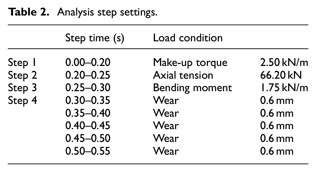
The rotation of the blade in the fourth step was not about the global coordinate system. Instead, a local coordinate system was established along the position where the wear took place, and the blade was rotated along the x-axis direction of the newly established local cylindrical coordinate system to complete the cutting process.
Contact settings
The contact setting for tubing joint wear consisted of two parts. The first part was the face-face contact algorithm, which included three contact groups of pin thread tooth to box thread tooth, pin thread sealing surface to box thread sealing surface, and pin shoulder to box shoulder. The face-face contact pair algorithm should clearly indicate the contact surface and the subordinate relationship. The second part was to define the contact between the blade and the wear area of joint by using general contact algorithm.
In the process of building worn tubing joint model by cutting method, the setting of contact attribute should consider the contact relationship between blade and joint.
In the tangent direction, the friction property between the blade (set as rigid body) and the joint was defined as “rough” contact. When the blade contacted the wear layer of the joint and moved along the tangential direction, the worn layer would be cut off. In the normal direction, the contact property between the blade and the joint was defined as “hard” contact. In view of the constant change of contact state in the cutting process, the corresponding control statements were added in the model file, so that the cutting separation surface could be extracted in real time and new contact pairs could be formed in the cutting process, so as to avoid contact state mutation caused by cutting separation as much as possible.
Criteria for chip separation
As the blade moves, chips cut from the wear layer will be separated from the joint body. There are roughly two criteria for judging whether chips are separated from the workpiece, namely, geometric criteria 22 and physical criteria. 23
The geometric criterion is mainly based on the change of the distance between the tool tip and the nearest node in front of the tool tip on the preprocess path to judge whether the separation is finished. When using geometric criteria, the chip is separated from the joint body by a separation line, which is the preprocess path previously mentioned. The physical criterion is defined based on the physical quantity of the element node before the tool tip, such as strain, stress and strain energy. In finite element calculation, it is considered that element node separation occurs when the corresponding physical quantity of element exceeds the critical value of given material. Different physical quantities will lead to form different separation criteria. Compared with geometric criteria, physical criteria has more specific physical meanings. 23 Therefore, the plastic strain value of the element was taken as the criterion in this study, that is, the critical plastic strain value of the grid element failure was defined in the material properties. For the material used in this model, the strain value “shear failure” at the time of failure is set to 0.146. When this critical value was reached, the chip was considered to separate from the joint body.
The stress characteristics on the sealing surface of tubing premium joint
Internal wear
The internal crescent wear caused by sucker rod was analyzed, as shown in Figure 6. The outer diameter of sucker rod is R1 and the inner diameter of tubing threaded joint is R.

Internal wear.
Axial contact stress on the sealing surface
In the elastic range, good sealing performance can be guaranteed only when the contact stress is high and the contact band width is large. We selected a row of nodes along the axial direction on the sealing surface of the wear side of the pin end of tubing joint, as shown in the red nodes in Figure 7, and named it A-P (Axial Path), then observed the change of contact stress on A-P at different wear depths.

A-P of internal wear.
Figure 8 shows the change of contact stress along the sealing path on the side where sealing surface internal wear occurs with the different wear depths. In the model of this study, the sealing width does not change with wear depth (all is 2.87 mm), so we only focus on the change of contact stress.

Contact stress on A-P at different wear depths.
As can be seen from the figure, with the increase of wear depth, the maximum contact stress along the axial path A-P is 403.4 MPa when the joint is unworn, and drops to 260.1 MPa when the joint is worn by 3 mm, decreasing by 35.5%. This is because as the wear depth increases, the stiffness of the sealing face decreases, and its bearing force decreases relative to other positions of the sealing face, so the contact stress in the wear area is relatively small. It can be found that the axial contact stress on the wear side of the sealing surface decreases greatly when the internal wear depth increases from 0 to 3 mm, indicating that the internal wear seriously weakens the sealing performance of the tubing joint.
Circumferential contact stress on the sealing surface
In order to observe the change of circumferential contact stress of tubing joint when internal wear occurs, a circle of main stress points along the circumferential direction of sealing surface were selected as the circumferential path, named as C-P. See the red dots in Figure 9.

Circumferential path-C-P.
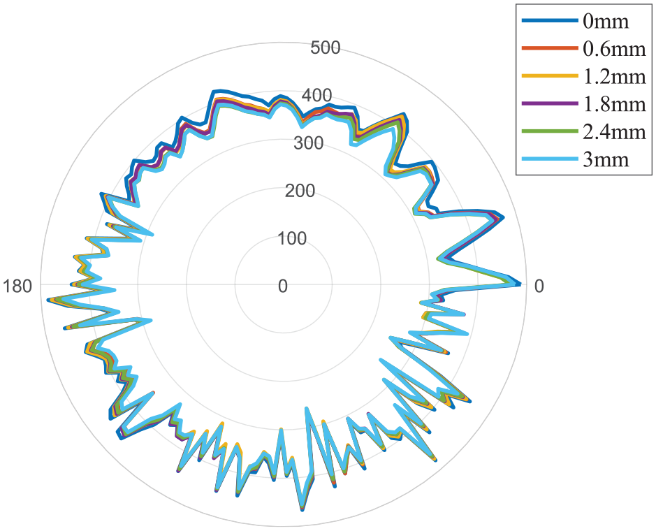
The contact stress distribution along the circumferential direction of sealing surface of the internal wear joint was shown in Figure 10. It can be seen that the contact stress along the C-P of unworn joint distributes between 200 and 500 MPa, and the uneven distribution is caused by the friction action by make-up and the three-dimensional spiral angle existed in the screw threads. With the increase of wear depth, the stress changes significantly in the section of the wear area (as shown in Figure 10, the red dotted line circle), while there is no significant difference in stress in most areas of the circumferential circle.

Contact stress on C-P at different wear depths.
As can be seen from Figure 10, the contact stress curves on the six C-Ps are closely fitted in most areas with little change under different wear quantities. Only the wear area circled by the red dotted line in the figure shows that the stress value changes greatly with wear, and the contact stress values become smaller with the increase of wear depth. It should be noted that the contact stress on the wear area is not the minimum one on C-P, which is due to the bending moment applied to the joint. As shown by the arrow direction in Figures 6 and 10, the bending moment is applied along the Y-axis which results in compression on the side pointed by the arrow and the contact stress in this side is relatively small. While, the contact stress on the opposite side is relatively large, and due to the action of additional tension, the contact stress curve on this side has the phenomenon of “flattening,” and fluctuates less than other areas.
In order to further quantify the decrease of circumferential contact stress with wear depth, the average contact stress of the wear section of sealing surface along the path of C-P were calculated, as listed in Table 3.
The average contact stress on C-P internal wear section.

As can be seen from Table 3, the contact stress on the worn section of the sealing surface decreases with the increased wear depth. When the wear reaches 3 mm, the contact stress decreases from 396.3 MPa of the unworn joint to 302.3 MPa, a decrease of 27.3%. As the C-P circle point is the maximum force point along circumferential direction, this indicates that the maximum stress value along the sealing direction decreases seriously with an increased wear depth, which further proves that the wear will damage the sealing performance of the tubing joint.
External wear
External wear of premium joint of tubing is showed in Figure 11, that is, contact wear occurs between the outer wall (outer diameter R″) and the inner wall of the casing (inner diameter R2″). The total outer wall wear depth of the tubing joint was also set at 3.0 mm (red part of Figure 11). Similarly, a complete tubing joint was established and applied with complex loads, then cut layer by layer.

External wear.
Axial contact stress on the sealing surface
Firstly, the contact stress on A-P (Figure 12) on the sealing surface of the externally worn tubing joint was observed, as shown in Figure 13. The contact stress on corresponding points on A-P decreases continuously with the deepening of wear, but the decreased value is very small compared with internal wear. When the wear reaches 3 mm, the maximum contact stress on A-P decreases from 384.5 to 369.1 MPa, which is only 4% lower than that of unworn condition. It can be seen that the external wear has little effect on the axial stress distribution of the sealing surface of the tubing joint and almost no effect on the sealing performance of the joint.

A-P of external wear.

Contact stress on A-P at different wear depths.
Circumferential contact stress on the sealing surface
The contact stress on the sealing surface of the externally worn tubing joint along the path C-P is showed in Figure 14. It can be seen that the overall contact stress distribution characteristic along circumferential circle on the sealing surface of the outer wear joint is roughly similar to that of the internal wear joint, and the distribution curve is also characterized by fluctuations. The contact stress curves of different wear depths fit closely and have similar form.
Contact stress on C-P at different wear depths.
Table 4 shows the average contact stress of circumferential wear section on the sealing surface of external wear joint. It is found that with the increased wear depth, the average contact stress decreases slowly, from 375.3 MPa of the unworn joint to 348.3 MPa of 3 mm wear, only decreasing by 7.2%.
The average contact stress on C-P external wear section.

This means that the effect of external wear on the stress distribution on the sealing surface of the tubing joint is much less than that of internal wear.
Comparison and discussion
Xu et al. 8 established the radial interference contact stress theoretical model of the main sealing surface of special thread joint by using the thick-walled cylinder theory of elasticity and Hertz contact mechanics theory. This model uses the section through the thread axis to cut the thread and expand it along the thread circumference, simplifying the ball-cone seal structure into a two-dimensional contact problem between a cylinder and a plane, as shown in Figure 15. The tangential friction force is ignored, and only the normal contact stress PsN is considered, and the following assumptions are made: (1) the contact surfaces are continuous and discordant; (2) small strain; (3) tubing and contact seal structures are both regarded as elastic half-space bodies; (4) ignore contact surface friction.

Schematic diagram of ball sealing facing cone: (a) initial contact and (b) final contact.
The normal contact stress of the ball-cone sealing surface is thus obtained:

Where, PsN(x) is the normal contact stress at position x, MPa; Eb and Ec are respectively the elastic modulus of the tube body and the joint, MPa; Rs is the radius of the sphere, mm; δsN is the normal interference of the spherical surface and the cone at the initial contact point after the N turn of the make-up, mm; the νp and νc are the Poisson ratios of the tube body and the joint, respectively, and are dimensionless. δsN can be determined by the following formula:

Where Ns is the number of make-up loops attached to the sealing surface, loops; P is pitch, mm; γs is the sealing surface half cone angle, degree.
For the model in this article, it is a special threaded tubing joint of P110 steel grade with an OD of 114.3 mm and a wall thickness of 6.45 mm, the elastic modulus of the tube body and joint are both Eb = Ec = 210,000 MPa, the Poisson ratio of the tube body and joint are vp = vc = 0.29, and the radius of the sphere is 15.0 mm. By plugging these parameters into equation (1), we can obtain:
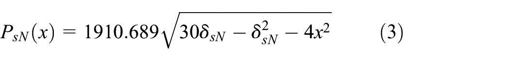
The make-up torque is 2.5 kN/m, which is converted to 0.05 turns. Substituting Ns = 0.05, taper 1:16 and pitch 4.23 mm into equation (2), the corresponding interference of sealing surface at this time can be obtained

Figure 16 is a comparison between the contact stress curve calculated by the formula (4) and the contact stress translated by coordinates on the A-P path of the unworn model by finite element method in this article.

Comparison diagram of contact stress of sealing surface under make-up torque calculated by analytical method and finite element method.
As can be seen from Figure 16, the axial distribution of contact stress obtained by two-dimensional analytical method presents a regular semi-elliptic shape, in which the initial contact area stress is high and gradually decreases along the edges of both ends, with a maximum value of 810.6 MPa, and the width of the sealing contact belt is 0.49 mm. The contact stress simulated by the three-dimensional finite element method is approximately parabolic in axial direction, forming a sealing belt with higher contact stress and wider sealing belt on the whole, which is quite different from the contact stress characteristics of the sealing surface calculated by the analytical method. The maximum contact stress value is 411.3 MPa. The bandwidth of the sealing surface is 2.87 mm. The reason for such a big difference in results is the analytical method uses linear elastic materials, the stress value will increase linearly, resulting in a larger maximum stress value. Moreover, since it is a two-dimensional model, the three-dimensional lifting Angle is not considered. However, the finite element method uses elastic-plastic materials and considers the spiral Angle, so the results are more in line with the actual situation, this also shows the necessity of three-dimensional model and nonlinear calculation.
Conclusion
In this article, we proposed a worn tubing joint modeling establishment method “numerical cutting method” which is closer to actual condition compared with the conventional construction method, and the model is successfully implemented the three-dimensional finite element nonlinear calculation. Through the finite element calculation, the mechanical characteristics of the tubing joint seal surface with internal and external wear were revealed. We can draw conclusions as follows:
(1) “Numerical cutting method” proposed in this study can be successfully used to establish a worn premium joint of oil tubing under complex loads. Application of this method can also be used to simulate the dynamic wear processes in the future.
(2) The external wear has less influence on the stress distribution of the sealing surface within the calculation scope of this study. The stress distribution of the sealing surface during external wear is close to that of an unworn joint.
(3) The sealing performance of the metal-metal sealing surface of the premium joint mainly depends on a higher contact pressure and a larger sealing belt width. The local contact stress of the sealing surface at the wear part is obviously reduced due to the internal wear, which is easy to form a leakage channel and increases the risk of sealing failure. More attention should be paid to the prevention of internal wear during operation.
Footnotes
Handling Editor: Chenhui Liang
Declaration of conflicting interests
The author(s) declared no potential conflicts of interest with respect to the research, authorship, and/or publication of this article.
Funding
The author(s) disclosed receipt of the following financial support for the research, authorship, and/or publication of this article: This research was supported in part by the National Natural Science Foundation of China (52174003, U1663205, 51704191, 51804194).