
Abstract
The existing models of undeformed chip thickness for face milling found in the literature neglect the radial rake angle of the tool, and they assume that its value is zero. The effect of the variation of the radial rake angle has not yet been discussed in the literature. As a novelty, this article investigates such an effect, especially the effect on chip thickness. A new tool model is proposed that takes into account the radial rake angle. A new method to calculate the chip thickness has been developed that uses the new tool model and is based on several existing numerical and approximation methods. It is analytically proved that the effect of the radial rake angle must be taken into account for calculating accurate results; however, in the case of lower feed rates, that effect is insignificant. The presented procedures are evaluated with respect to their accuracy and computing requirements. The proposed new methods have been verified by cutting experiments.
Introduction
Having precise information about chip thickness is necessary in numerous cases of manufacturing. It is essential for determining the chip cross-section, the cutting force, and the specific cutting force. Furthermore, it is necessary for process modeling, including the tool life, micro- and macrogeometrical features, and stability.
In the case of milling operations, the chip thickness is a changing value, and it does not only depend on the tool geometry but also on the angular position of the tool. In order to solve the complex problem of determining the chip thickness, there exist several methods. However, none of them deal with the radial rake angle of the tool.
The different methods presented below suppose the radial rake angle is equal to 0°. Note, the axial rake angle or helix angle is 0° in all the presented methods. The use of geometrical simplifications and approximations can cause a negligible error in the case of a low feed rate. However, if the feed rate is increased
For the determination of the chip thickness, it is necessary to know the path of points of the tool edge which is determined by the speed of rotation and linear feed rate. Martellotti1,2 in his research used cycloid curves in the 1940s, and later on Saï et al. 3 and Spiewak 4 confirmed the correctness of this model. The description of cycloid curves is necessary in both workpiece-fixed and tool-fixed coordinate systems, and related computation can be made simpler and faster using approximation techniques. The presented numerical, theoretically accurate, method presupposes that the path of a given point on the cutting edge forms a cycloid curve.
The simplest approximation of undeformed chip thickness (h)
5
takes into account the feed rate (fz) and the angular position of the tool
Taking the similarity between the shape of the circle and the cycloid curve into account, a relatively simple relationship can be deduced analytically for the calculation of the chip thickness.1,8 In practice, this method can be deemed quasi-accurate when the tool radius, r, is much higher than the feed rate per tooth: r ≫ fz. Therefore, this method is favored by several researchers. The path of tool edge points, with respect to a coordinate system fixed to the tool, was successfully described by Spiewak. 4 Using these points, the chip thickness can be determined more accurately on the basis of the deduced transcendent equation. 9 Such equations are specific because they can only be solved numerically, and current computer algebraic software tools are suitable for that.
Another possible way is to approximate such trigonometric functions using polynomials or Taylor series which provide closed-form solutions. This method is also used by numerous researchers.1,5,6,9,10 In their approximation, Zheng and Kang 11 used a Fourier series form. The first 5 coefficients were determined in a defined range based on the feed rate and tool radius. Cheng et al. 12 proposed an accurate numerical model to determine the instantaneous uncut chip thickness. In the scope of all methods, the radial rake angle is hypothesized to be 0°.
In the work of Abram et al. 13 undeformed chip thickness is defined as the normal distance between the current and previous paths of the edge, but the radial rake angle of the tool is not considered either. Zerun et al. 14 made a sophisticated model for five-axis general end milling. They estimated the instantaneous undeformed chip thickness with the normal distance of the tool envelope surface at time t and t – Δt. Wanqun et al. 15 examined the cutting force in micro-milling. In their model, the machining dynamics and the trajectory of the tool center are considered. However, the cutting edge and chip thickness are simulated on a line determined by the center point of the tool and tool tip, which means that the radial rake angle is 0°. In an investigation of minimum chip thickness in micro-milling, 8 a geometrical solution (CAD software) is used to measure the chip thickness in discrete points; however, the radial rake angle is not used as a variable in the model. Xiaohong et al. 16 examined the undeformed chip thickness in micro-milling, considering the radial runout of cutting edge. The radial rake angle was also supposed to be 0°. Ding et al. 17 simulated the kinematics of micro-milling. The tool cutting edge is symbolized with a line, and it starts from the center point of the tool and ends in the tool tip. Thus, the radial rake angle is 0°.
This article presents the improved version of the most often used methods that calculate the chip thickness. The aim of the improvement is to take the radial rake angle into consideration with a more accurate tool model.
The improved models were verified with slot milling experiments where the cutting force was measured and processed. The measured force was compared to the estimated force. There are many empirical, mechanical, analytical, numerical, and hybrid models for milling10,12,14,18–29 and micro-milling processes7,15,24,30–35 to estimate the cutting force. Mechanical models are the most often used. In the simplest equations, the main cutting force Fc is proportional to the cross-section of the chip.18,19,25 Taylor 37 proposed another empirical, exponential function. In this expression, exponential coefficients are actually associated with all the input parameters. The estimated output parameter is the product of one or more constants and the power of input parameters and exponential coefficients. A similar expression was proposed by Kienzle and Victor 36
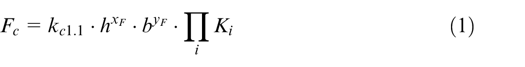
In equation (1), h is the chip thickness, b is the width of the chip, and kc1.1 is the main value of the specific cutting force belonging to the unit chip cross-section (h = b = 1). With the help of Ki, other environmental effects can be considered. Equation (1) has been used successfully by several researchers for cutting process planning,15,19–21,25,27,28,37 and it is also applied in this article. Assuming that

After processing the results of several experiments, researchers observed that xK and kc depend on the chip thickness.7,18–20,30,38,39 The expected values of cut-off points are
Definition of undeformed chip thickness
Let us start by examining the case shown in Figure 1(a). Here, the tool is milling a slot where the examined edge is cutting in an intermittent way. In the case of low feed rates, the range of cut is approximately 180°; however, the actual range is somewhat bigger. The undeformed chip thickness gradually increases to the actual feed rate fz and then decreases to 0. The axial immersion angle of the cutting edge is
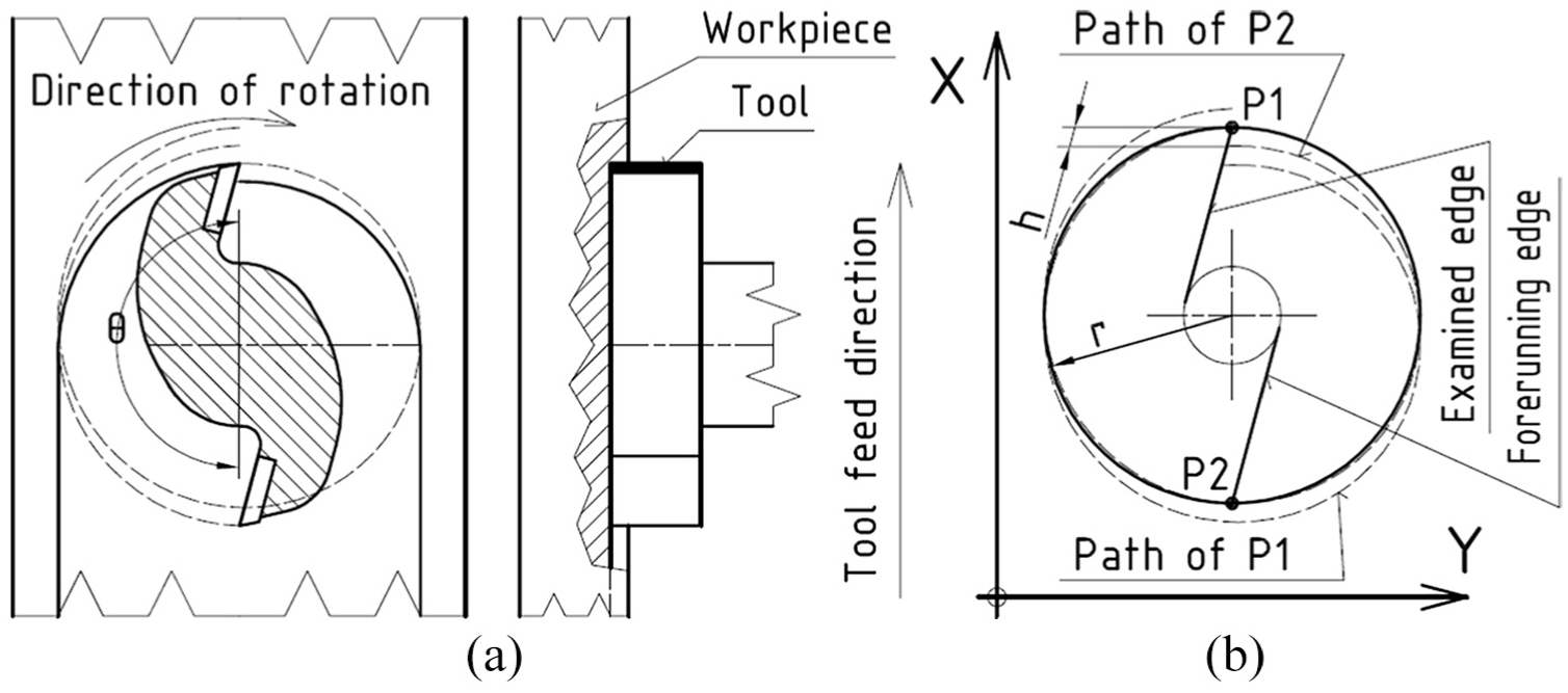
(a) Arrangement of face milling and (b) determination of undeformed chip thickness.
The undeformed chip thickness h is determined on the basis of the paths of two points: P1 on the examined edge and P2 on the forerunning edge (see Figure 1(b)).
Chip thickness can be determined unambiguously and is equal to h if the direction and magnitude of speed vectors at the points touched by the chip on the examined edge are identical. If the value of h is significantly lower than that of the tool radius, that is,
For the determination of chip thickness, it is necessary to know the theoretically accurate path of point P1 located on the cutting edge. With the help of equations (26) and (27) described in Supplemental Appendix A1, the cycloid curve can be transformed (translated and rotated) in an arbitrary way. By converting the sequence of transformations and setting up a new constant, the cycloid curve can be described in a coordinate system fixed to the tool. This makes the search for the intersection points simpler. It should be noted that in Zerun et al. 14 homogeneous transformation matrices are used; however, in the case of face milling, a simpler solution can also be applied. The deduction of cycloid curves can be found in Supplemental Appendix A1.
Tool model
Milling tools generally have a certain radial rake angle:
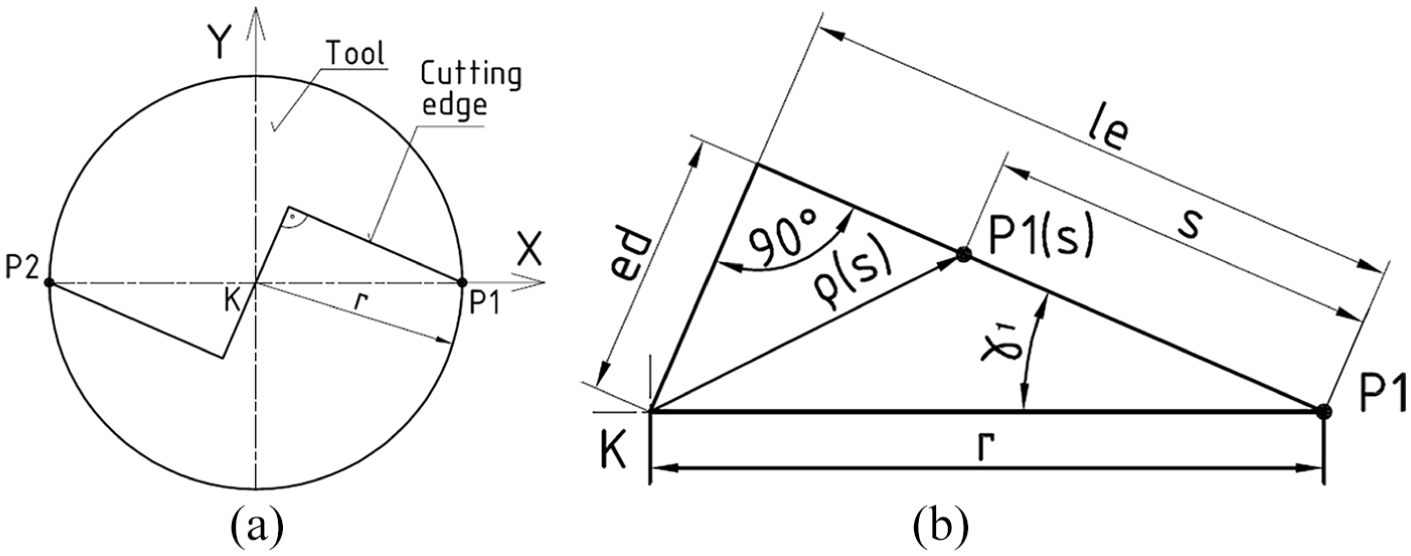
(a) Geometric model of the tool and (b) triangle defined in the tool model.
Let the possible maximum working length of the cutting edge be le. Any point along the edge can be described by the parameter s. The radius belonging to point P1(s) is
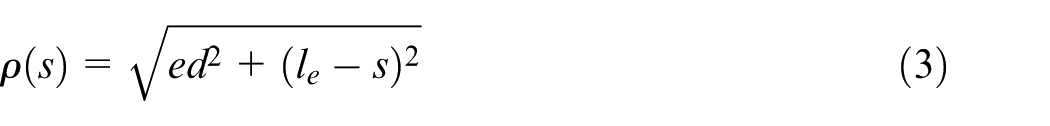
Based on the two extreme points of equation (3),


In case the coordinate system is fixed to the workpiece,
The starting points of the two cutting edges, P1 and P2 (Figure 3), are needed to determine the chip thickness and identical to the same points in Figure 1. The cycloid path of P1, when s = 0 is substituted into equations (4) and (5), in the function of t is:
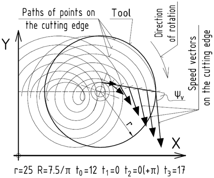
Direction of speed vectors along the cutting edge.
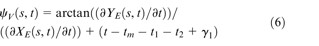
The magnitude and direction of the speed vectors of points on the cutting edge are different. It is necessary to know the angle between the speed vectors and the cutting edge
Determining the undeformed chip thickness
With the help of the proposed tool model, the calculation methods of chip thickness can be improved. The individuality and novelty of these improved methods is the fact that radial rake angle is a variable parameter. Comparing these methods, numerical solutions are the most precise.
In case of low feed rates (fz ≪ r), the paths of points P1 and P2 on the tool tip can be substituted with a circle.1,2 This method significantly simplifies the computation of chip thickness. Moreover, this approximation method can be extended so that it considers the radial rake angle as well.
The sine and cosine functions in the x- or y-component equations of the cycloid curve can be substituted by their respective Taylor series3,32,40,41 (see Supplemental Appendix A2.3). Through the increase of x, the resulting approximation error clearly grows.
With these methods, the undeformed chip thickness can be calculated more or less accurately for any radial rake angle, feed per tooth value, and real angle between two subsequent edges. These three parameters (fz, γ1, and θ) are the only inputs.
If a simple, continuous equation is necessary to describe the undeformed chip thickness, an approximating polynomial can be fitted to the values calculated by the numerical method. It is adequate only for one setting of fz and γ1. If this polynomial is needed for a series of fz and γ1, then other polynomials must be determined to describe the constants of the original polynomial series. The resulting expression has numerous constants; nonetheless, it expresses the undeformed chip thickness explicitly for a specified range in fz and γ1.
Effect of the radial rake angle
Change of chip thickness in time
The effect of radial rake angle was examined with the numerical method described above using the following parameters: tool radius: r = 25 mm, number of teeth: 1, and number of calculated points: N = 128. The applied values of radial rake angle expressed in degrees (L = 19 pcs) are:
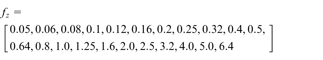
The applied values of feed per tooth expressed in millimeters (M = 22 pcs) are
The computations and the figures presented in the article were made with the help of a commercial computer algebraic software. The results are presented below.
Two properties of chip thickness were examined. First, the maximum value of chip thickness was inspected. The ratio of the maximum value of the length of the chip that is in contact with the cutting edge and the feed per tooth is expressed as follows:
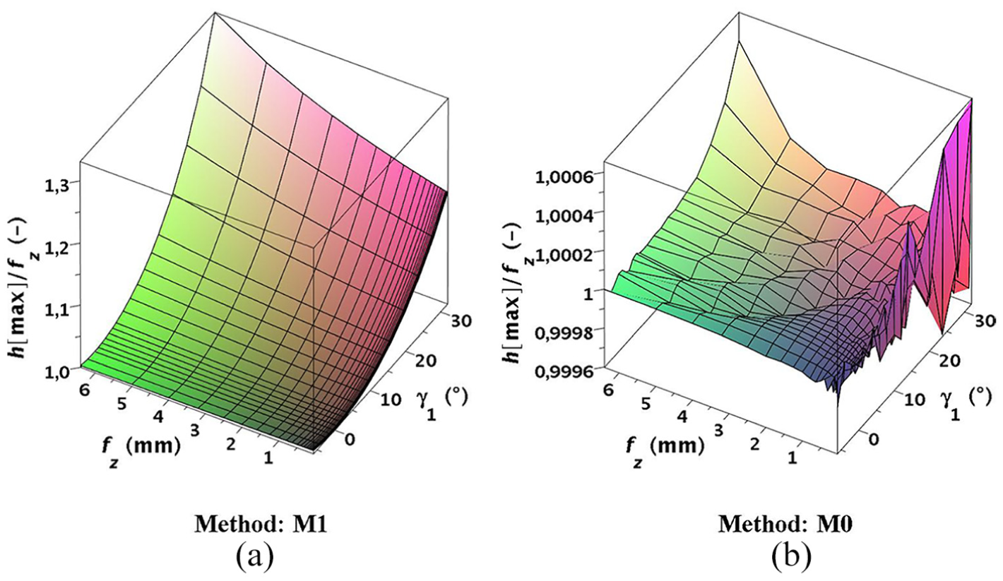
(a) The values of
Second, the value of t (tool angular position) was examined when the chip thickness was at maximum. If fz and/or γ1 increase(s), the value of t changes. The location of the maximum value of chip thickness does not change significantly if the directions of the speed vectors are taken into consideration. According to Figure 5, the maximum angular shift is 17°. The change in chip thickness is asymmetric and the period of the increase in thickness is the longer one.
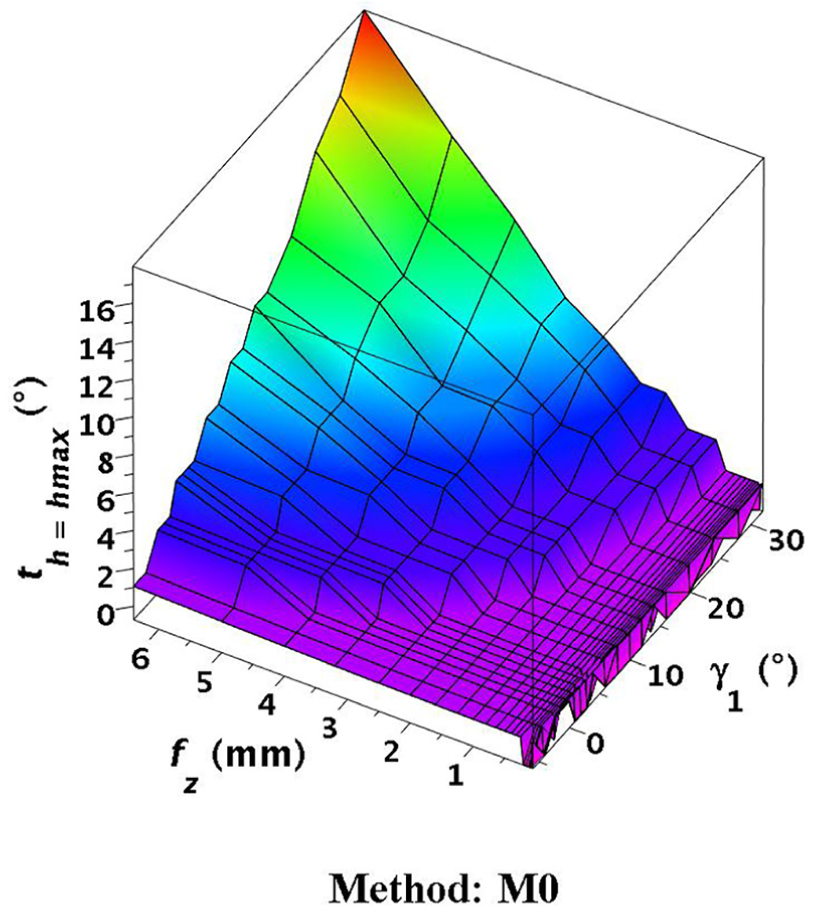
The values of t (tool angular position) belonging to
The undeformed chip thickness was calculated with the methods presented above, using the parameters described at the beginning of this section. The different methods can be compared to each other according to their computing requirements. The mean and standard deviation values of the difference between the numerical method (M1) and other methods (see below) provide information concerning the limits of applicability of the approximation techniques. In addition, the start- and endpoints of the cut as well as its full range were examined.
Computing time of the different methods
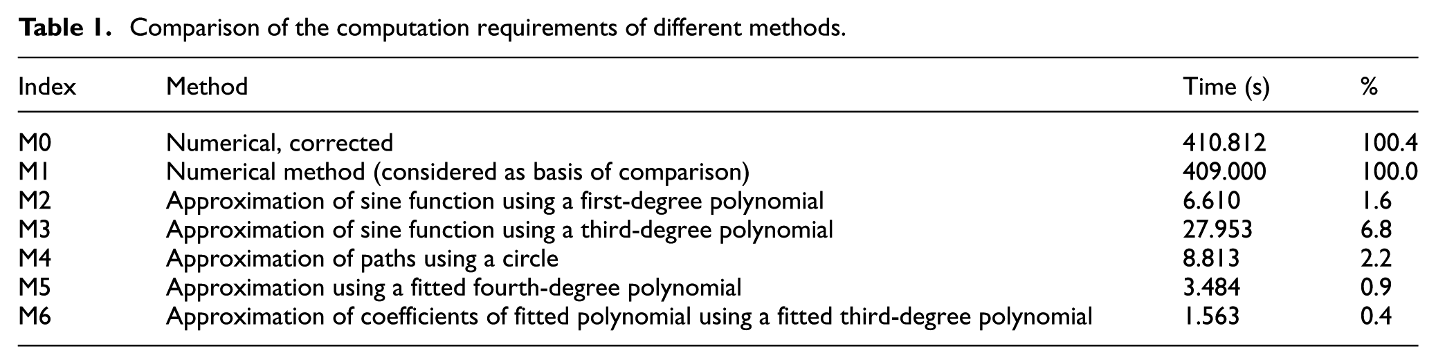
The computing time concerning all fz and γ1 parameters applied in our calculations is summarized in Table 1. In the case of other fz and γ1 values, the calculation time and the relative calculation time of the different methods compared to the numerical method (Mi/M1) in percentage may differ. Computing times are influenced by the hardware and the applied software. The presented results were calculated using a standard personal computer. In the case of the numerical method, the computation time increases slightly if the directions of the speed vectors are taken into account (M0). Computing time in the case of approximation techniques (M2-M6) can be as little as one hundredth compared to the one of the numerical method.
Comparison of the computation requirements of different methods.
Means and standard deviations of the differences of chip thickness
The chip thickness has been calculated in numerous points with different methods. The results were collected in an array:
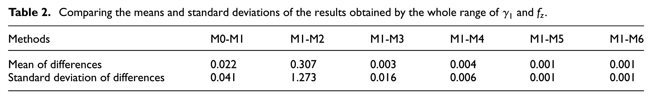
Comparing the means and standard deviations of the results obtained by the whole range of
In this case, the mean is expressed as
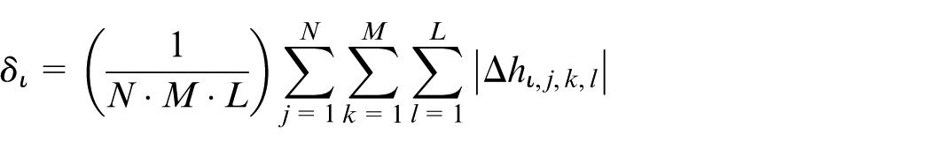
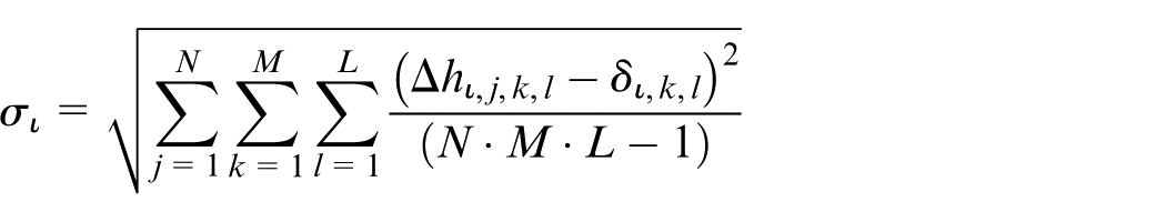
and the standard deviation is expressed as
Investigation of the angular interval of cutting
The start- and endpoints of the cut,
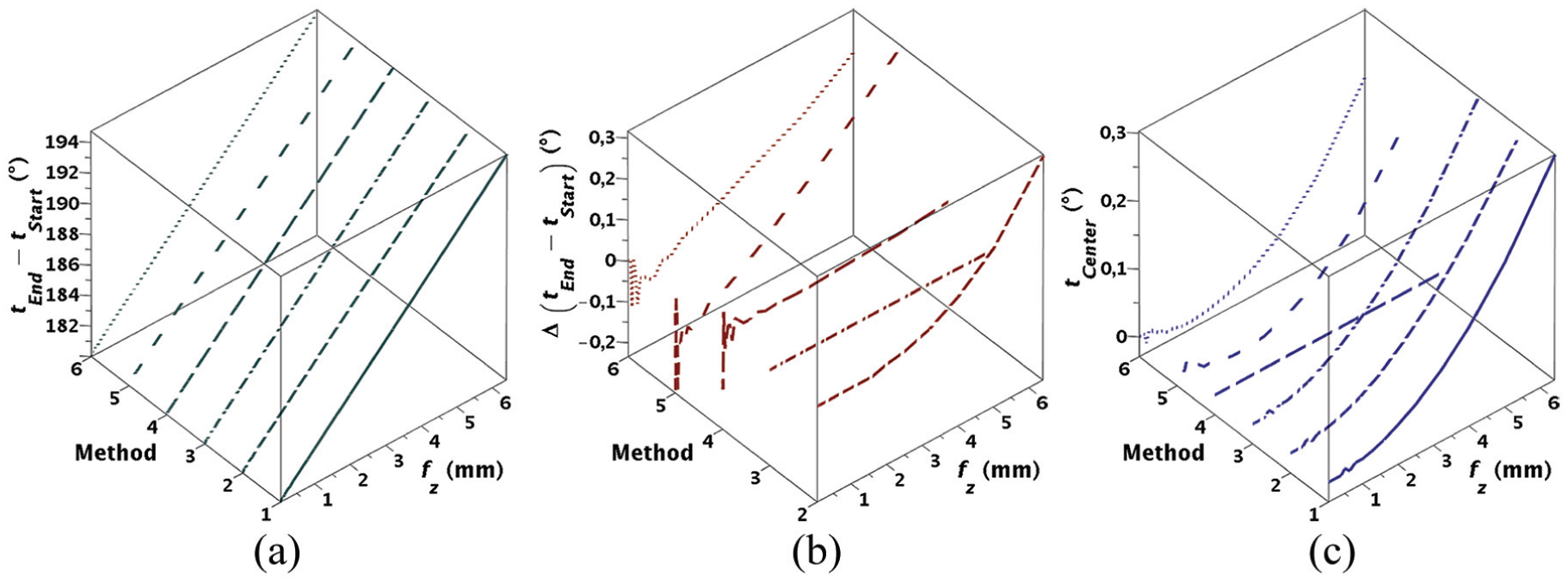
(a) Angular intervals belonging to the cutting, (b) deviation of intervals obtained by the different approximation methods, and (c) deviation from the axis of the feed (axis of symmetry).
Verification using experimental cutting
Experiments have been conducted where the components x, y, and z of the cutting force were measured with respect to four different feed per tooth values. The resultant force can be obtained either from the vector sum of the components x and y of the cutting force or from the vector sum of the main cutting force (Fc) and the edge force (Fp) as follows
The main cutting forces and edge forces can be calculated according to equations (8) and (9), where φ is the angular position of the tool


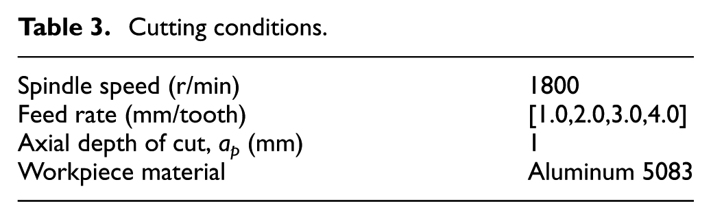
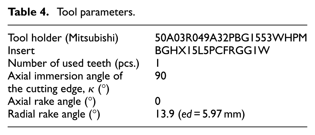
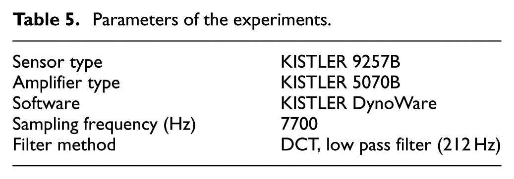
The experimental setup is shown in Figure 7. The machine tool was a 3-axis machining center, type Kondia B640, the cutting conditions are detailed in Table 3, and tool data are presented in Table 4. The distance between the edge and the center point of the tool (ed in Figure 2) was measured using a coordinate measuring machine. During the experiments, the cutting force was measured with a KISTLER 9257BA three-directional load cell; its accessories are listed in Table 5. Due to the high values of the resulting cutting force when 3 and 4 mm feed/tooth was used, the workpiece had to be fixed directly to the load cell.
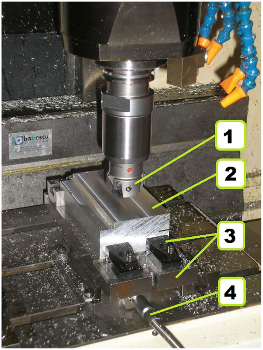
The experimental setup: (1) tool, (2) workpiece, (3) fixture and support, and (4) Kistler load cell.
Cutting conditions.
Tool parameters.
Parameters of the experiments.
The values of xF and kc1.1 in equations (1) and (2) can be determined using the chip thickness obtained with the help of the corrected numerical method (M0). In the case of each feed per tooth value, 12 complete rotations of the tool were examined. The results of the evaluations are shown in Table 6. The explanations of the rows are the following:
Calculated values of the constants in the expressions of the cutting force.
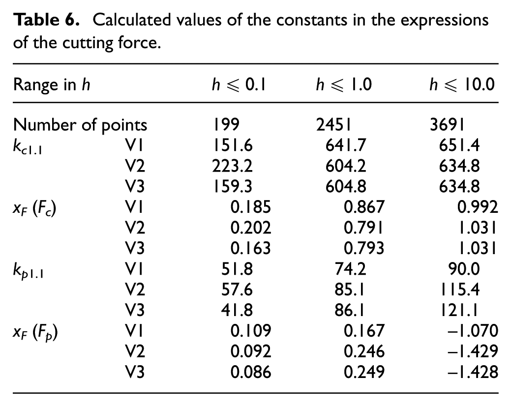
V1: Evaluation of all measured data.
V2: The mean of the regression data belonging to each feed rate, separately.
V3: The mean of the regression data belonging to each feed rate per each rotation, separately.
For instance, the measured points and regression lines for the main cutting force (Fc) belonging to fz = 4 and to all the 12 rotations are shown in Figure 8.
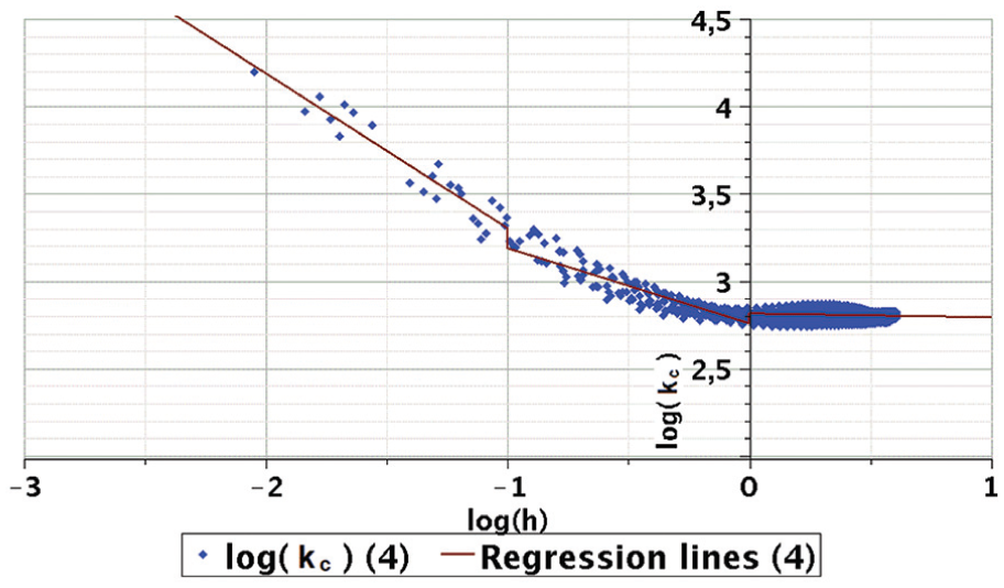
Measured points and regression lines for the main cutting force Fc, in the case of fz = 4.
With the help of the constants determined with respect to all measured points (V1) and equation (1), the main cutting force (Fc) and the edge force (Fp) can be estimated. Based on the main cutting force and the edge force, the components x and y of Fx and Fy can be determined as follows


Figure 9(a)–(d) shows the measured and estimated values of the main cutting force, edge force, and components x and y, respectively. The predicted forces are depicted in the case of the estimated and 0° radial rake angle. The results of methods M0-M1 are shown because the results of methods M2-M6 are near to the results of method M1. The difference is not significant between the two cases whether the radial rake angle is considered or not. It would be bigger, if the radial rake angle or the feed per tooth value were bigger. However, it is too limited to increase these values because, in general, the radial rake angle is a small and fixed value and the feed per tooth is limited by the power and construction of the machine tool.
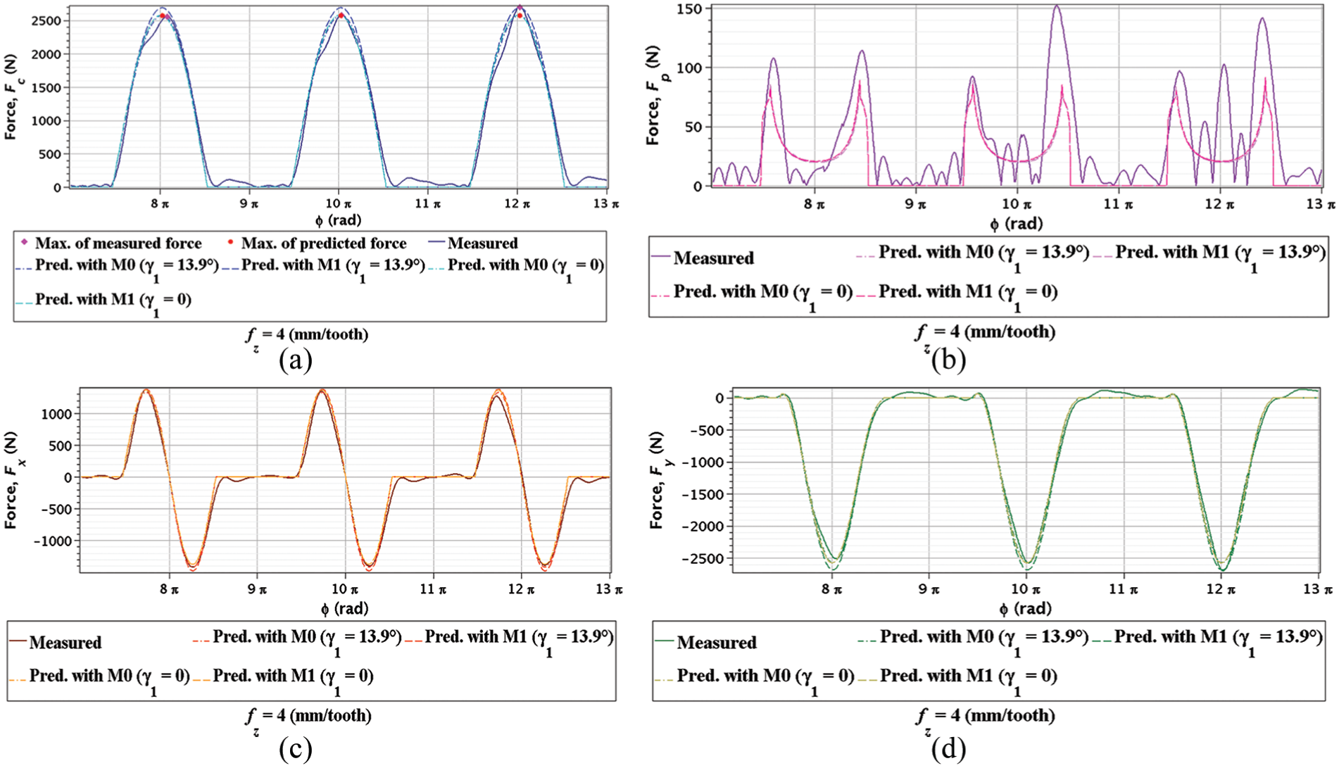
Measured and estimated values of (a) Fc, (b) Fp, (c) Fx, and (d) Fy in the case of fz = 4 mm.
If the force components, that is, the main cutting force and edge force, are compared, the main cutting force is much higher than the edge force, independent of the process parameters (except micro-milling). The edge force has relatively bigger error; however, its effect is not significant. Therefore, the error of the force components, X and Y, will be the same as the main cutting force.
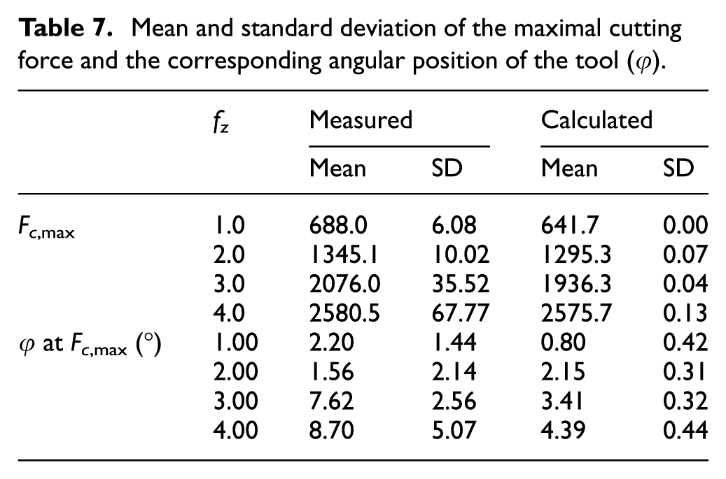
The maximum values of the main cutting force and the corresponding angular position of the tool φmax were determined as follows. The measured and predicted force values are summarized in Table 7, where it can be seen that the maximum of the main cutting force shifts from the line of feed direction (if
Mean and standard deviation of the maximal cutting force and the corresponding angular position of the tool (φ).
The difference between the measured and estimated values of the main cutting force (ΔFc) and the two measured components x and y (ΔFx and ΔFy) have also been examined. The mean and standard deviation of the relative error
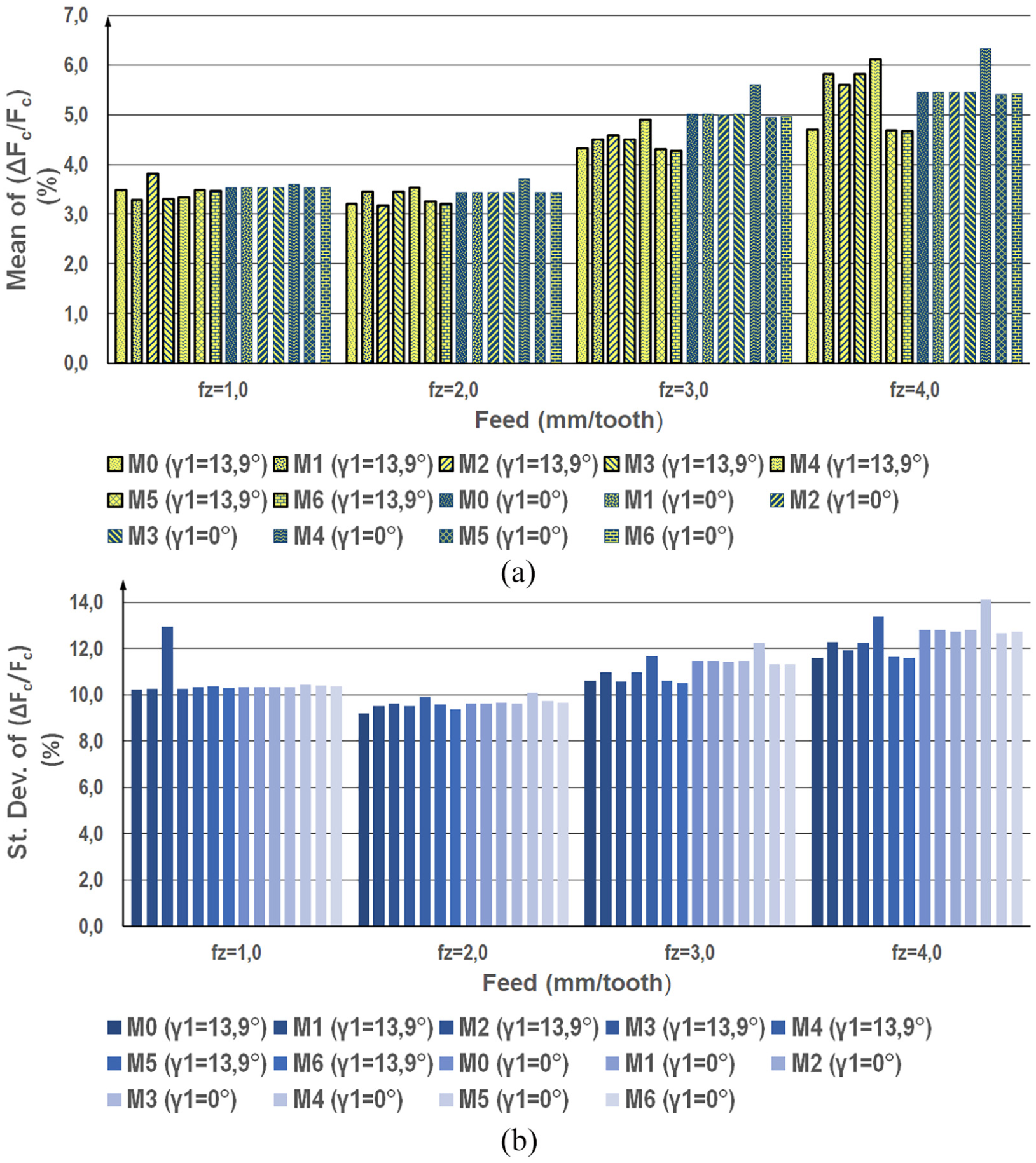
Comparison of the difference between the measured and estimated values of main cutting force: (a) the mean and (b) the standard deviation of the relative error.
Conclusion
In this study, the effect of radial rake angle on chip thickness has been examined. A new tool model has been proposed that takes into account the radial rake angle. The calculation methods of undeformed chip thickness have been developed, where the radial rake angle γ1 is comprised as a variable. The errors of five approximations (M2-M6) compared to the numerical method keep increasing with the increase in the radial rake angle and also with the feed rate. The approximation methods have small error in a usable range of radial rake angle and feed rate. The error is significant (>10%) only in the case of approximation through the linearization of the sine function and at very low feed rate.
Another outcome is the fact that the change of chip thickness is asymmetric with respect to the angular position of the tool. If the radial rake angle is not zero, that is, γ1 > 0 or γ1 < 0, then the duration of the growth period of chip forming is longer. By the increase of the radial rake angle, the contact length of the chip also increases. However, with respect to speed vectors, the effective load remains unchanged.
The computing requirements of the approximations are significantly lower than those of the numerical method. If computing time is significant, approximation may prove useful. Even if the computing time is long, the actual radial rake angle and feed rate should be taken into account.
The orientation of the tool at the start- and endpoints of the cut can be estimated with the help of approximating methods. Analysis has shown that accurate values can be obtained in this manner
The constants in the Victor and Kienzle’s cutting force expression can be determined slightly more accurately if the radial rake angle is taken into account. The effect of the radial rake angle is not relevant in the case of regular feed rates. However, the effect of the radial rake becomes more important in the case of HFM. Finally, as has been demonstrated, changes in the main cutting force are asymmetric and the duration of the growth period of chip forming is longer.
Supplemental Material
Supplemental_Material – Supplemental material for The effect of radial rake angle on chip thickness in the case of face milling
Supplemental material, Supplemental_Material for The effect of radial rake angle on chip thickness in the case of face milling by György Póka and István Németh in Proceedings of the Institution of Mechanical Engineers, Part B: Journal of Engineering Manufacture
Footnotes
Appendix 1
Acknowledgements
The authors are grateful to Gyula Mátyási, who shared with us many of his thoughtful insights and gave inspiration in the course of this research.
Declaration of conflicting interests
The author(s) declared no potential conflicts of interest with respect to the research, authorship, and/or publication of this article.
Funding
The author(s) disclosed receipt of the following financial support for the research, authorship, and/or publication of this article: Work for this paper was supported by the European Commission through the H2020 project EPIC under grant No. 739592 and by the Higher Education Excellence Program of Ministry of Human Capacities in the frame of Artificial Intelligence research area of Budapest University of Technology and Economics (BME FIKP-MI).
Supplemental material
Supplemental material for this article is available online.
References
Supplementary Material
Please find the following supplemental material available below.
For Open Access articles published under a Creative Commons License, all supplemental material carries the same license as the article it is associated with.
For non-Open Access articles published, all supplemental material carries a non-exclusive license, and permission requests for re-use of supplemental material or any part of supplemental material shall be sent directly to the copyright owner as specified in the copyright notice associated with the article.