
Abstract
High-speed spindle systems could generate sufficient heat when they are operating and would cause thermal deformation that influences spindle accuracy. Heat dissipation is a common and effective way to remove the generated heat. In this paper, heat conductive paths were created on the bearing seat and the spindle housing along the radial direction. Along these paths, the heat was transferred directly from heat sources inside the spindle system to outside and the heat dissipation was enhanced. To limit the heat transferred along the axial direction, the inner wall of the path was coated with a thermal insulation material. Based on an annular plate model, the influences of the affecting parameters of paths on the heat transfer performance were studied. The temperature distributions of the models with and without heat conductive paths were numerically and experimentally investigated. It was found that after using heat conductive paths, the heat dissipation enhanced significantly. Moreover, it is found that as the number and diameter of paths increases, the temperature of internal parts decreases and the gap between the highest and the lowest temperature is narrowed.
Introduction
As industrial technology develops, requirements for accuracy and speed in machine tools grow ever more stringent. In order to improve the efficiency of machine tools, a high-speed spindle system has been widely used in diverse applications. However, when the spindle is rotating at a high speed, significant heat is often generated due to the friction between the rotating elements and the inner/outer stationary rings of the spindle bearing. Then the generated heat flows into different parts of the spindle system along different directions and at different heat rates, which may lead to an unevenly distributed temperature field and thermal deformation. Studies show that the thermal deformation may bring about thermal errors of the spindle along the axial and radial directions, thereby affecting the accuracy of the machine tool.1–3
In order to resolve this problem, numerous methods, including replacing the steel material of some parts in the spindle with low-thermal expansion coefficient materials (e.g., ceramic, carbon-fiber-reinforced plastics),4–6 and thermal error compensation7,8 have been proposed. Heat removal strategy is also an important and effective way to reduce the temperature rise in the rotating parts and control the thermal error. In engineering applications of the spindle system, a cooling jacket with spiral channels is commonly adopted through which a cooling fluid flows circularly to dissipate heat by the forced heat convection mechanism.9,10 Using the finite element method, Wang et al. 11 analyzed the thermal characteristic of the spindle in a CNC milling machine. Then the correlation between the temperature of the front bearing and the flow rate of the cooling fluid was studied. Moreover, Chen et al. 12 performed experiments and studied the influence of the ambient temperature and the working conditions on the spindle temperature. In the abovementioned studies, the temperature and flow rate/flow volume of the cooling fluid was constant. Li et al. 13 found out that adjusting the cooling oil flow rate according to the spindle speed and machining loads improves the heat removal efficiency and reduces the warm-up time of the machine. Liu et al.14,15 proposed a differentiated multi-loop cooling strategy in which different cooling parameters were used for different parts of the motorized spindle. Recently, some innovative structure channels such as improved U-shaped channels, 16 reciprocating cooling channels, 17 fractal tree-like channels, 18 and a convex structure channel 19 have been proposed to replace conventional spiral channels in the spindle cooling system to improve the heat dissipation performance. However, the temperature inside the spindle was still high.
In the present study, heat conductive paths are proposed to resolve the heat removal problem of the high-speed spindle system. The heat conductive paths were built on the bearing seat and the spindle housing along the radial direction. One end of the path was connected to the outer ring of the bearing, while the other end was connected to the cooling system outside the spindle. The paths were filled with high thermal conductivity material to ensure that the heat transfers directly and effectively from the internal heat sources to the outside of the spindle system.
It should be indicated that heat conductive paths have been adopted to solve the volume-to-point problem and enhance the heat dissipation in the field of electronics, 20 but this method has not been used to dissipate spindle heat so far. In 1996, Bejan 21 developed a network of branching high-conductivity paths to resolve the heat dissipation problem when there exists a volumetric heat generation source. Wu et al. 22 optimized the tree-like distribution of the high conduction channels and analyzed the correlation between the thermal resistance of the model, aspect ratio of elements, and the construction order of the tree-like distribution. Based on the biological evolution principle, Cheng et al. 23 constructed the heat transport paths. For the convenience of manufacturing, the constructs were regularized. Moreover, the topology optimization method was used to determine the distribution of conducting paths.24–26 Compared with bionic optimization structure and tree-like network, the topology method improves the heat transfer performance of the conducting paths. 27
Different from the volume-to-point problem, the heat generation and cooling boundary conditions of the high-speed spindle are complicated. This issue was analyzed in Section “Heat transfer model of the spindle with heat conductive paths.” The heat transfer model of the spindle with heat conductive paths was simplified to an annular plate. The influences of path parameters on the model resistance were investigated. In Section “Thermal characteristics of the model with heat conductive paths,” the temperature field of the model with heat conductive paths was analyzed numerically using ANSYS-Workbench software, and the results were verified with the mathematical analysis results. To evaluate the heat dissipation enhancing effect after using the heat conductive paths, several tests were conducted on a test platform and the obtained results were discussed in Section “Thermal characteristics of the model with heat conductive paths.”
Heat transfer model of the spindle with heat conductive paths
Heat generation and cooling boundary condition
A conventional mechanical spindle system mainly consists of bearings, the shaft, the bearing seat, and the spindle housing. In the present study, bearings are considered as the main heat source. The heat generation of the bearing Htot is proportional to the rotating speed and the friction torque. This can be mathematically expressed as follow 17 :

where n is the spindle speed, r/min. M0 and M1 are the friction torques related to the viscous friction and bearing load, N/m, respectively. Moreover, ωsi denotes the spin angular velocity of the rolling body in the bearing, rad/s, and Msi is the spinning friction torque, N/m.
The studied spindle system has two sets of 7010C bearings, which is one of the widely used angular contact bearings in the spindle systems. The main parameters of 7010C bearings are shown in Table 1. The heat generation of the spindle can be calculated from equation (1). The main assumption of this article is that the generated heat flows equally into the outer and inner rings. 28 The calculated heat generation at 10,000 rpm is shown in Table 2. To simplify the calculations, it is assumed that the temperature of the outer surface of the bearing seat is kept constant at 25°C.
Main parameters of 7010C angular contact bearing.

Heat generation of the bearing (at 10,000 rpm).

Simplified heat transfer model of the spindle with heat conductive paths
Bearings are the main heat generation source in the spindle system. 4 This is especially more pronounced when the spindle is running at a high speed. In this case, significant heat is generated and flows into the bearing seat and the spindle housing, which may cause thermal deformation and bring about thermal error. In the present study, it is assumed that heat conductive paths were built on the bearing seat and the spindle housing in the radial direction. One end of the path was directly connected to the outer ring of the bearing, while the other end was connected to the cooling system. Moreover, copper as a high thermal conductivity material was filled in the path to improve the heat transfer from the internal heat sources to the outside of the spindle system. To limit the heat transferred along the axial direction, the inner wall of the path was coated with a thermal insulation material. Figure 1 presents the simplified model of the bearing seat and the spindle housing. The black structures are the heat conductive paths.
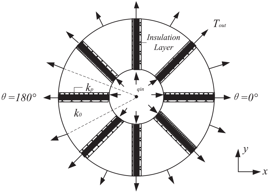
Simplified heat transfer model of the spindle with heat conductive paths.
In this model, heat flux from the outer ring of bearings qin flows from the inner rim into the annular structure. It is assumed that the outer rim of the model was kept at a constant temperature Tout. Moreover, N heat conductive paths were distributed equidistantly along the circumference. The thermal conductivities of the materials filled in the paths, and other parts of the annular plate were k0 and k1, respectively. Since there was an insulation layer in the inner wall of the path, the heat flux could only be transferred along the radial direction.
Since the model is symmetric, only 1/N of the model with one thermal conductive path was analyzed. Figure 2 shows the configuration of the model section, in which
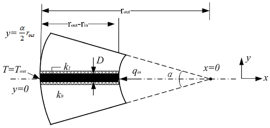
Heat transfer in the model section with one heat conductive path.
In the present study, thermal resistance was used to calculate the heat transfer. The lower the thermal resistance, the higher the heat dissipation. The thermal resistance is defined in the form below:

where ΔT is the temperature difference, °C, Q denotes the heat flow, W, q is the heat flux, J/(m2 s), and S is the cross-section area, m2.
According to Figure 2, the circular sector consists of two parallel parts, including a part with the heat conductive path filled with copper and another part filled with 45# steel. Therefore, the thermal resistance of the sector with only one heat conductive path Rone-path can be calculated as follows:

where R1 and R0 are the thermal resistances of a heat conductive path (black structure) and the other part.
Based on equation (2) and Fourier’s law, R1 can be obtained in the form below:

where S1 is the cross-sectional area of the path,
For a regular sector with no heat conductive path, the thermal resistance Rsector can be expressed as follows:
where
So,

Similar to equation (3), Rsector can be rewritten in the form below:

where

Then the thermal resistance of the sector with one heat conductive path filled with copper can be obtained.

where
Finally, the thermal resistance RN of the plate can be expressed as follows:

Analysis of affecting factors
Equation (6) indicates that the lower the thermal resistance, the higher the heat dissipation. The more copper is used in the model, the thermal resistance is lower. It is worth noting that copper is softer than commonly used materials in the spindle system such as 45# steel. Consequently, its volume ratio Φ should be limited to meet the stiffness and intensity requirements. The volume ratio Φ can be expressed as follows:
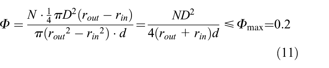
The number and the diameter of paths are limited as well.

Meanwhile, copper is 15 times more expensive than 45# steel. In this case, the material cost of the whole model C is:

Equation (10) indicates that
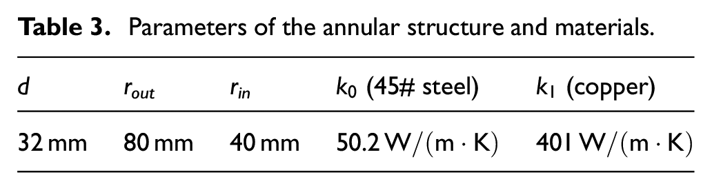
Parameters of the annular structure and materials.
Based on equations (12) and (13), N < 18 if D = 13 mm, while D < 19.6 mm if N = 8. The correlation between N, D, RN, and C is shown in Figure 3.

Correlation between parameters: (a) distribution of RN, and C against N (D = 13 mm); and (b) distribution of RN, and C against D (N = 8).
Figure 3 reveals that as the number of paths N and the path diameter D increases, the corresponding total thermal resistance of the annular plate model RN decreases while the material cost C increases. Therefore, the acceptable values are N∈ [6, 12] and D∈ (6,16 mm).
Thermal characteristics of the model with heat conductive paths
Thermal characteristics of the model with single row of paths
According to Figure 1 and Table 3, a three-dimensional annular plate model was built. Based on ANSYS-Workbench software, thermal characteristics of the model with and without heat conductive paths were analyzed. The process of the numerical analysis is shown in Figure 4.

Process of thermal characteristic numerical analysis.
The models are meshed automatically. Figure 5(b) illustrates the meshing results of established model with eight 13 mm diameters heat conductive paths, which contains 236,055 elements and 612,124 nodes. The mesh quality is 0.85, which can meet the requirement of simulation.

Three-dimensional annular plate model: (a) without heat conductive path, (b) with heat conductive path, and (c) the meshed model.
In the present study, it is assumed that half of the generated heat in the bearings transfers from the outer ring to the inner rim of the model. Based on the obtained results, the heat flux is 40,000 W/m2. As the inner wall of the path was coated with insulating material, it was considered an insulated boundary. The temperature of the outer rim of the model is considered as 25°C constantly. Finally, the temperature distribution of the model was obtained in steady-state conditions.
The temperature simulation results of the models are shown in Figures 6 and 7. Compared with the model without heat conductive paths, temperature shown in Figure 6(a) is lower. The highest temperature of the model with heat conductive paths is decreased from 42.4°C to 37.2°C. The average temperature of the inner rim reduces by 30%. It reveals that more heat flows through the heat conductive paths.
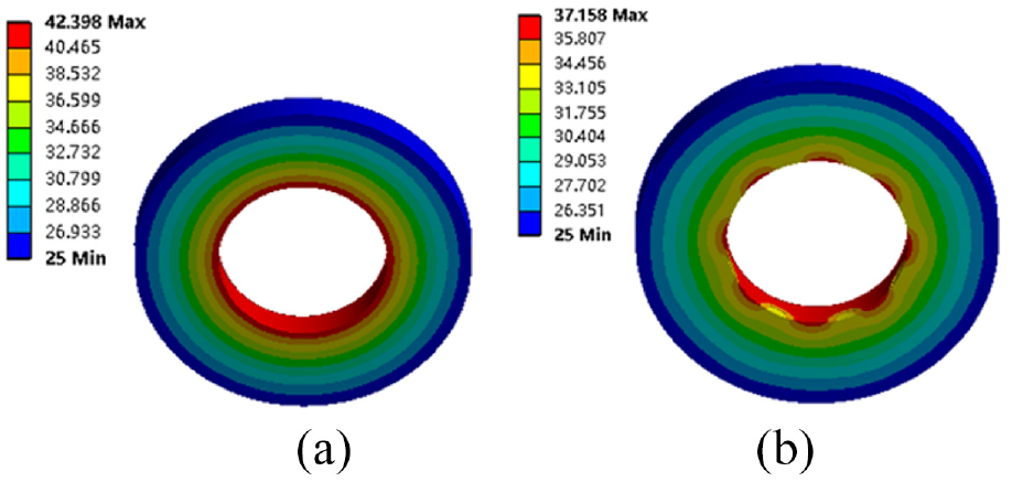
Steady-state temperature distribution of the model: (a) without heat conductive path and (b) with heat conductive path.

Steady-state temperature distribution of the inner rim: (a) without heat conductive path and (b) with heat conductive path.
Similarly, the impacts of D and N were studied. In this regard, Figures 8 and 9 indicate that as the values of N and D increase, the average temperature of the inner rim decreases. More specifically, when N = 8 and D = 11 mm, the average temperature is 31°C.
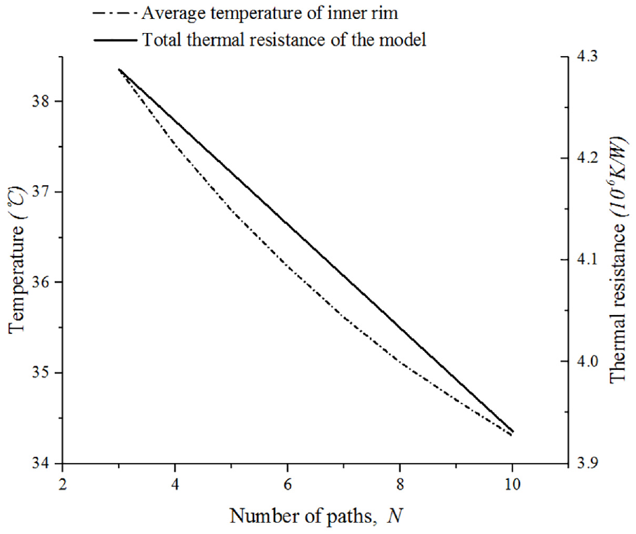
Distribution of the average temperature of inner rim and thermal resistance against the number pf paths N (D = 13 mm).

Distribution of the average temperature of inner the rim and the thermal resistance against the path diameter D (N = 8).
To verify the performed numerical analysis, the model resistances are presented in Figures 8 and 9. It is concluded that the distributions of the average temperature and the resistance are consistent with each other, indicating that the proposed model can be used to study the heat dissipation performance of the spindle with heat conductive paths.
It is worth noting that the ratio of thermal conductivity material Φ is a critical parameter that affects the thermal characteristics of the model. The higher the value of Φ, the higher the amount of the thermal conductivity material in the model, and the lower the thermal resistance and the temperature of the model. Figure 10 shows the temperature distribution of the inner rim for Φ = 0.088 and different values of N. Moreover, the temperature curves are shown in Figure 11. It is observed that the gap between the highest and lowest temperature of the inner rim is narrowed when the value of N increases. It is inferred that increasing the number of heat conductive paths while Φ is constant uniforms the temperature distribution. However, when N ≥ 8, the difference between the highest and the lowest temperature almost remains constant.

Temperature distributions of inner rim at different N, while Φ = 0.088: (a) N = 4, (b) N = 6, (c) N = 8, (d) N = 10, and (e) N = 14.

Temperature distribution of the inner rim when Φ = 0.088.
Thermal characteristics of the model with two rows of paths
In addition, two rows of paths were established as shown in Figure 12. The parameters of the structure were shown in Table 4. The materials of the plate and the paths were the same with the model with one row of path.

Three-dimensional annular plate model with two rows of paths: (a) paralleled placed and (b) interlaced placed.
Parameters of the annular structure with two rows of paths.

Similarly, heat flux of 40,000 W/m2 is loaded on the inner rim and the temperature of the outer rim of the model is 25°C. Then the temperature distribution of the model with two rows of in steady-state conditions was shown in Figures 13 and 14. According to the simulated results, the temperature distribution and the inner rim temperature are similar no matter the two paths was placed paralleled or interlaced. It turns out that the paths arrangement has little impact on thermal characteristics of the model.
Steady-state temperature distribution of the model with two rows of paths: (a) paralleled placed and (b) interlaced placed.

Steady-state temperature distribution of the inner rim: (a) paralleled placed and (b) interlaced placed.
Experimental verification
Testing set-up
In order to test the thermal characteristics of the model and verify the effect of heat dissipation after using heat conductive paths, an experiment platform was prepared. Figure 15 shows the configuration of the test platform.

Configuration of the experiment platform.
In the test platform, the testing samples could be assembled in the cooling jacket which was supported by a V-block. The cooling jacket was connected to the cooling system to maintain the temperature of the cooling water at 25°C. There is a heater installed close to the inner surface of the sample (Figure 16). The input heat power was controlled by the temperature control system. To ensure that the generated heat transfers evenly into the sample, a thin sleeve was placed between the heater and the inner surface of the sample, and all the contact surface was coated with heat-conducting silicone grease. In this paper, the thermal infrared imaging camera (FLIR, X6520sc, Sweden) was used to obtain the temperature distribution at the end surface of the sample, while the PT100 thermocouples were used to collect the temperature changing of the sample.

Assembled testing sample.
Test results
According to Section “Heat generation and cooling boundary condition,” half of the generated heat transfers into the model. By adjusting the temperature control system, the output power of the heater on the inner surface of the sample was set to 45%, which is equivalent to 290 W. After heating for 30 min, both samples with and without heat conductive paths have reached to the steady-state condition. The temperature field of the testing samples are shown as follow.
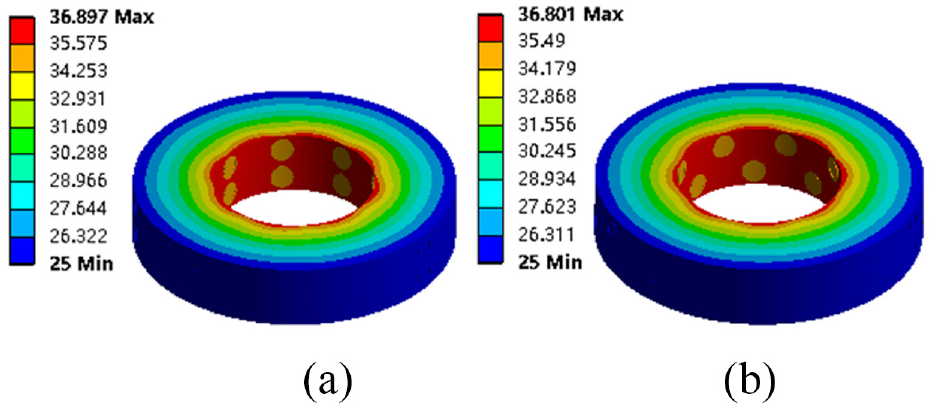
Figure 17 reveals that the temperature in the area close to the heat source is very high. Moreover, the area of high temperature higher than 46°C in the sample without heat conductive paths is larger than that in the sample with heat conductive paths. In order to further analyze the results, a black circle is drawn around the inner rim. The temperature of all the pixels along the perimeter of the circle is averaged and labeled as Tcircle to evaluate the heat dissipation performance of the model. It is found that compared with the sample without heat conductive paths, Tcircle of the samples with heat conductive paths (N = 8, D = 13 mm) decreased from 51.7°C to 46.9°C. Taking 99% of the highest temperature as the criteria, it cost 854 and 1122 s respectively for the samples with and without heat conductive paths to reach to the steady state.

Temperature distribution of the testing sample at the steady-state condition: (a) sample without heat conductive path and (b) sample with heat conductive path (N = 8, D = 13 mm).
Similarly, averaged temperatures Tcircle of samples with different N and D values were calculated and the obtained results are shown in Figure 18. It is observed that as N and D increase, the corresponding Tcircle reduces. When D is set to 13 mm, as N increased from 4 to 8, the corresponding Tcircle reduced from 48.2°C to 46.9°C. Moreover, when N is 8 and the sample diameter was increased from D = 9.2 mm to D = 16 mm, Tcircle decreased by 2.4°C.
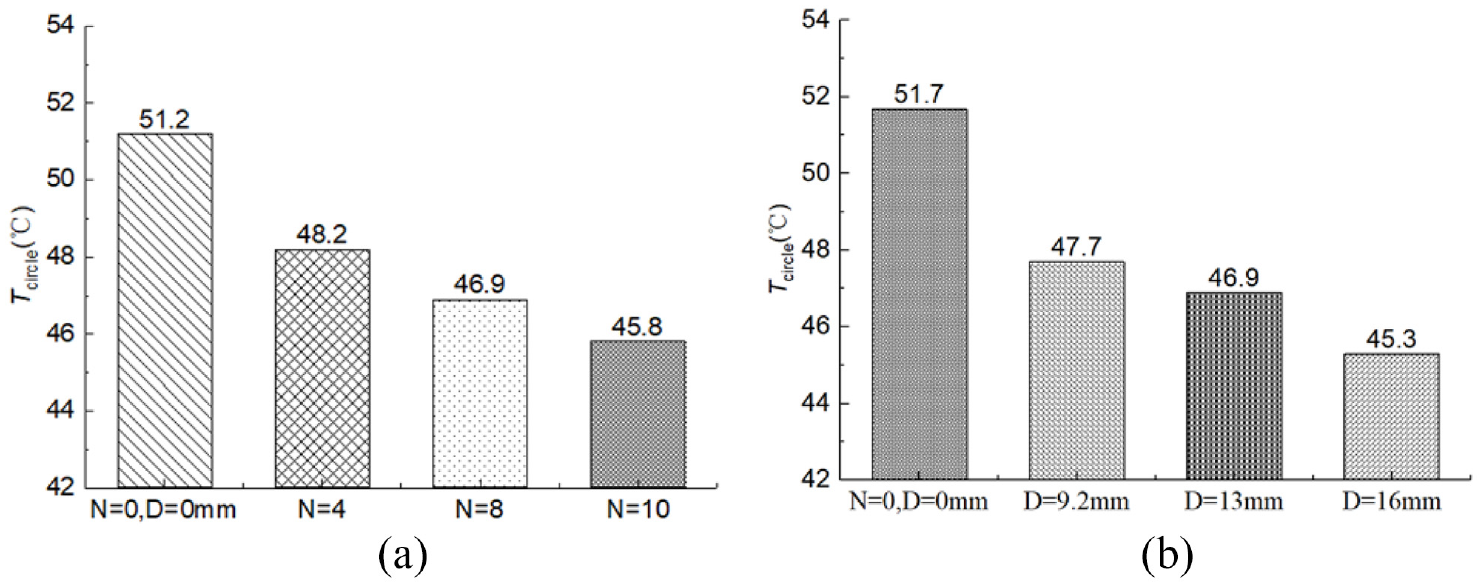
Tcircle of the samples with different parameters: (a) D = 13 mm and (b) N = 8.
Moreover, the simulated temperature around the black circle is compared with testing result. It can be seen from Figure 19 that Tcircle of the simulated and tested models with heat conductive paths are both lower. The ratio of reduction by using the heat conductive paths is all around 10%. Based on the obtained results, it is concluded that after using heat conductive paths, the average temperature of the annular plate decreases, demonstrating that the heat dissipation improves.

Tcircle of the simulated and tested model (D = 13 mm, N = 8).
In order to investigate the thermal characteristics of the annular plates with two rows of paths, five temperature sensors were placed along the circumstance of the testing samples (Figure 20) to measure the temperature changes along the axial direction. The structural parameters of the testing samples were the same as shown in Table 4.

Test samples: (a) temperature sensor location, (b) without heat conductive path, (c) with one row of heat conductive paths, (d) with two rows of paralleled heat conductive paths, and (e) with two rows of interlaced heat conductive paths.
In this experiment, the heat transferred into the structure is 65 W which is provide by setting the output power of the heater as 10%. The heat is dissipated by natural convection. In order to make sure that the heat flows radially but not axially, two end surfaces of the testing sample were covered by thermal insulation material mainly consisting of cobaltous oxide whose heat conductivity coefficient is 0.025 W/(m K). The highest, the lowest and the average temperatures of different testing samples in the steady state are compared and shown in Figure 21.

Temperatures of different testing samples in the steady state.
According to the testing results, it can be seen that the temperature of the testing sample with two rows of heat conductive paths are lower than the samples without or with only one row of paths. When the paths are distributed interlaced, the heat dissipation performance of the sample is better. In addition, it takes less time for the sample with two rows of paths (198.4 min for paralleled paths and 196.9 min for interlaced paths) to reach to the steady state, as the time for the samples without and with one row of paths is 226.5 and 205.2 min.
Conclusions
In the present study, the heat dissipation performance of the high-speed spindle with heat conductive paths was investigated. Based on the obtained results, it is proposed to use heat conductive paths to enhance heat dissipation and reduce the influence of generated heat inside the spindle system on working accuracy. At the first stage, the spindle model with heat conductive paths was simplified as an annular plate. Then the correlation between the affecting parameters of paths (number of paths N and the path diameter D), the thermal resistance, and the material cost were established. It was found that the acceptable values are N∈ [6, 12] and D∈ (6, 16 mm). Moreover, the thermal characteristics of the model with heat conductive paths were numerically analyzed. The obtained results showed that when the volume ratio, and the number and the diameter of the heat conductive paths increase, the temperature of the inner rim of the model decreases. Finally, temperatures of annular plate samples with and without heat conductive paths were studied experimentally. It is found that compared with samples without heat conductive paths, Tcircle of the samples with heat conductive paths (N = 8, D = 13 mm) was decreased by 4.8°C, demonstrating that using the heat conductive paths improves the heat dissipation in the spindle system.
Footnotes
Handling Editor: Chenhui Liang
Author contributions
Conceptualization and methodology, YL; software and validation, MY and ZH; formal analysis and investigation, YB and ZH; resources, HZ; data curation, WW; writing – original draft preparation, MY and ZH; writing – review and editing, YL; supervision, WW; project administration and funding acquisition, YL and HZ. All authors have read and agreed to the published version of the manuscript.
Declaration of conflicting interests
The author(s) declared no potential conflicts of interest with respect to the research, authorship, and/or publication of this article.
Funding
The author(s) disclosed receipt of the following financial support for the research, authorship, and/or publication of this article: This research was funded by National Natural Science Foundation of China, grant number 52275509, National Natural Science Foundation of Shaanxi Province, grant number 2022JQ-487, and Key-Area Research and Development Program of Guangdong Province Grant, grant number 2020B090927002.
Disclaimer/publisher’s note
The statements, opinions, and data contained in all publications are solely those of the individual author(s) and contributor(s) and not of MDPI and/or the editor(s). MDPI and/or the editor(s) disclaim responsibility for any injury to people or property resulting from any ideas, methods, instructions, or products referred to in the content.
Data availability statement
There is no new data were created, or the data is unavailable due to privacy or ethical restrictions.