
Abstract
In the offset press, ink flows in the microchannel made of two rotating rollers that are in the state of squeezing and contacting. The ink flow characteristics are not only influenced by the viscous dissipation effect, but also change with the heat transfer. First, by summarizing the common viscosity–shear rate models of non-Newtonian fluid, the power law model was chosen for describing offset ink through rheometer measuring. Combined with the experimental data, the viscosity–temperature relationship of the offset ink was described by the Arrhenius’s law. Then, the temperature characteristics of the offset ink fluid in the microchannel were studied using the fluid simulation software FLUENT. The ink fluid temperature field model considering viscous dissipation and heat transfer was established, and the temperature distributions of the ink fluid inside the microchannel and at the exit and entrance were obtained. The influence of the feature size on the ink temperature was also researched. Finally, the ink temperature and flow characteristics were compared with that under the condition without heat transfer. We got the influence of feature size and heat transfer on the ink temperature characteristics. As the feature size is smaller, the ink temperature increase from the microchannel entrance to the exit, increases first and then decreases, and keeps invariant at last. The heat transfer makes the viscous dissipation weaken relatively and then the ink temperature decreases. In a word, the heat transfer enhances as the feature size decreases. The results provide reference for improving the printing quality of offset press.
Introduction
Nowadays, with the rapid development of social economy, the demand for printing quality is increasing. In order to improve the quality of offset printing, it is necessary to attach great importance to the temperature of the offset press because temperature is an important parameter in the work process of offset inking system. In the roller extrusion channel of inking system, the viscous dissipation effect will lead to the increase of internal ink temperature, and the heat transfer between the ink fluid and rollers may lead to the decrease of ink temperature. Besides, the ink viscosity decreases with the increase of temperature. When the temperature of the printing press is too low, the ink viscosity will be high and makes paper picking easy. On the contrary, when the temperature is too high, the ink viscosity will be low and the hue will be more. When the temperature changes, the viscous deformation of the ink should be as small as possible and the ink property also needs to be stable.1,2 Therefore, in addition to higher requirements for the ink quality, the analysis of the ink temperature field caused by viscous dissipation and heat transfer is particularly important for printing process.
In the printing ink transfer process, the ink channel height between two rollers of the extrusion zone is 0.05–0.5 mm. As the height is in the microscale range, it can be treated as a microchannel. 3 Many experimental studies have indicated that microchannels can enhance heat transfer, but the specific mechanism of heat transfer enhancement is still controversial. In addition, it also needs a large number of basic research and experimental verification. 4 Jiang et al. 5 researched the effect of viscous dissipation and variable properties on convectional heat transfer in porous media by theoretical analysis, numerical simulation, and experimental research. The results showed that it was not significant about the effect of viscous dissipation on convectional heat transfer in porous media, but the change of physical properties had a great influence on heat transfer. Gao et al. 6 investigated the effect of the microchannel height on the flow and heat transfer in microtubule. The experimental results showed that Nusselt number was obviously lower when the height of the microtubule was less than 0.4 mm. Under the condition of viscous heat generation, Morini 7 found that it was not negligible for the viscous dissipation effect of liquid flow through microchannels when the hydraulic diameter was less than 100 μm. As the scale decreases, the effect of parameters related to the gradient will increase in the microfluidic motion. And under the same temperature difference, the average temperature gradient increases, which improves the heat transfer intensity. It results in the increase of convectional heat transfer ability in the microscale.
The power law model is used to describe the rheological properties of non-Newtonian fluid. Compared with Newtonian fluids, the shear thinning fluid has distinctly different flow and heat transfer characteristics. Kumar et al. 8 numerically analyzed and studied the forced convectional around a heated semicircle cylinder of a kind of power law fluid (power law index ranged from 0.2 to 1.8) by ANSYS FLUENT. It was found that the total heat transfer rate increased with the increase of Reynolds number. Compared with Newtonian fluid and shear thickening fluid, the mean Nusselt number of the shear thinning fluid was greater, and the heat transfer enhancement was about 47% compared with Newtonian fluid. Mortazavi 9 analyzed the flow of pseudoplastic power law fluid under different power law exponents in the microchannel plate by computational fluid dynamics simulation. The results showed that the pseudoplastic fluid in the micro heat exchanger can reduce the pressure drop and increase the heat transfer efficiency than Newtonian fluid. The radial flow numerical simulation of non-Newtonian power law fluid in the rough wall fracture shows that when the flow behavior index changes, the flow pattern has slight but systematic change. When the index drops, the fluid becomes more radial, and the fluid becomes shear thinning. 10 As a non-Newtonian fluid, it is necessary to analyze the rheological characteristics and heat transfer characteristics of the offset ink in the microchannel between two rollers.
Presently in the study of offset inking system, the domestic and overseas scholars mainly focus on the ink flow characteristics and roller heat generating mechanism. But there are fewer analyses about the ink temperature characteristics. Han 11 simulated and analyzed the heat transfer process between the entire inking system of the offset press and the air. The temperature distributions of the rollers at different rotational speeds were obtained. However, the inking system is only a two-dimensional model, and the temperature change caused by the heat transfer between the ink fluid and rollers is not considered. Huang 12 obtained the viscosity–temperature relationship of yellow ink through experiments and simulated the influence of ink viscosity on the ink temperature field at steady state. However, the influence of the viscosity–temperature relationship and the properties of the interface material on the ink heat transfer are not considered. Shen et al. 13 and Cheng et al. 14 studied the influence of temperature on the printing properties of gravure offset by using contact angle measurement instrument. It was found that the ink contact angle was highly dependent of temperature, and high temperature would reduce the ink cohesion. Hence, the temperature increase improves the ink transfer performance in the transfer process, but reduces that in the set process.
The two rotating rollers that are in the state of squeezing and contacting in the offset press are, respectively, composed of hard roller and soft rubber roller. In general, hard roller is made of steel or plastic. The steel roller is selected to analyze in this article. But the microchannel made of rubber and steel is uncommon, and the heat transfer between rubber and ink has a certain effect on the ink temperature field. Therefore, it is necessary to research the temperature characteristics of the ink fluid considering viscous dissipation and heat transfer in the microchannel made of steel and rubber rollers.
In this article, the non-Newtonian fluid characteristics of the offset ink is considered. The ink flow field in the microchannel made of steel and rubber is simulated by the fluid simulation software FLUENT. The ink temperature characteristics and the flow characteristics, such as the wall shear stress, pressure, and velocity, under the interaction of viscous dissipation and heat transfer are studied. In addition, the influence of feature size and heat transfer are considered.
Materials and methods
Non-Newtonian fluid characteristics of offset ink
For the incompressible Newtonian fluid, the relationship between the shear stress and the shear rate accords with the law of Newtonian inner friction. And the kinetic viscosity (viscosity for short) is a constant independent factor of the shear stress and the shear rate. The relationship of the three parameters can be expressed as

While for non-Newtonian fluid, the relationship between the shear stress and the shear rate is no longer consistent with the law of Newtonian inner friction. Its viscosity is not only related to the shear rate, but also varies with the change of temperature. The viscosity of a non-Newtonian fluid can be expressed as

In the formula, η is the fluid viscosity (Pa s), it can not only represent the fixed viscosity of Newtonian fluid in formula (1) but also describe the apparent viscosity of non-Newtonian fluid in formula (2).
Models of viscosity–shear rate relation
According to the Zhang 15 and Moreno et al., 16 it is known that the following four non-Newtonian fluid models are commonly used.
1. Power law model (Ostwald model)

In the formula, k is the consistency coefficient (Pa sn). And n is the power law index, which is a dimensionless quantity that characterizes the deviation degree between the fluid and Newtonian fluid.
n = 1, it represents Newtonian fluid.
n > 1, it represents dilatant fluid and also known as shear thickening fluid.
n < 1, it represents pseudoplastic fluid and also known as shear thinning fluid.
2. Carreau model for pseudoplastic fluid
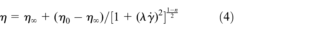
In the formula, when
3. Cross model

In formulas (4) and (5),
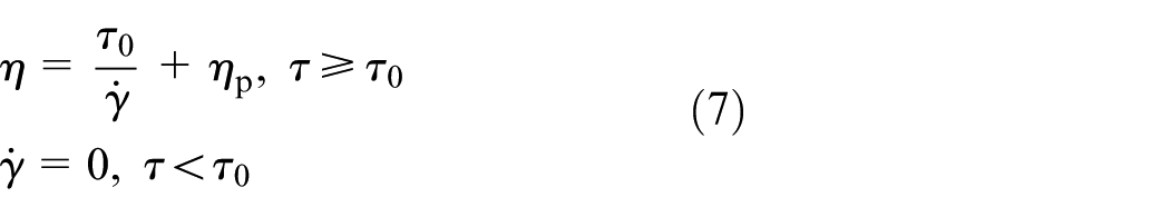
4. Herschel–Bulkley model for Bingham plastic fluid.
Power law model applies to the situation when

In the formula,
When n = 1, ηp = k and it means that the consistency coefficient has the same dimension as the viscosity. It indicates Bingham plastic fluid and can be seen as Newtonian fluid with a yield value. ηp is the plastic viscosity. The expression of the Bingham plastic fluid is as follows
Model of viscosity–temperature relation
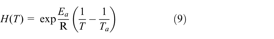
Temperature characterizes the degree of molecular heat movement, and the temperature increase makes the free volume of the polymer increase, which leads to viscosity decrease. For most fluids, Arrhenius’s law 17 can be used to indicate its viscosity–temperature relationship

In the formula, A is the pre-exponential factor and also called as experimental constant (Pa s). Ea is the viscous flow activation energy (KJ/mol). R is the gas constant (thermodynamic constant), usually R = 8.314 J/(mol K). T is the absolute temperature (K).
And then
Analysis of rheological properties of offset ink
Offset ink is a high-viscosity mixture. Its rheological properties mainly include viscosity, yield value, fluidity, and so on. Among them, the viscosity is the internal friction that obstructs the flow of itself between the layers. The printability of the ink requires stable viscosity when it is on the plate, but when the ink is transferred to the substrate, it would be better that the viscosity becomes larger quickly. 18
The relationship between the viscosity and the stress rate of offset ink
Liu18,19 indicated that, using the power law model or the Bingham plastic fluid model can better describe the rheological characteristics of offset ink. In order to determine the rheological model of the ink, the Brookfield R/S PLUS-CPS rheometer was used to measure the relationship between shear stress and shear rate of yellow ink under shear stress mode. The results of the experimental data are shown in Table 1. It concluded that with the rising of shear stress and shear rate, the ink viscosity first increased to 317.42 Pa s and then decreased.
The relationship between shear stress and shear rate at normal temperature 20°C.

The experimental data of the ink at normal temperature were analyzed and fitted according to formulas (3)–(7), respectively. The results were shown in Figure 1. And the parameters were illustrated in Table 2. Because the shear rate and shear stress begin to change from 0, the (0, 0) is seen as a data point to ensure that the fitted model passes through this point. Figure 1 indicates that the fitting results of Bingham model is the most unsatisfactory. The best fitting models are power law model and Carreau model, and their stability indexes R2 are 0.9872 and 0.9965, respectively. The closer the stability index is to 1, the better the consistency of the curve fitting and the experimental data.
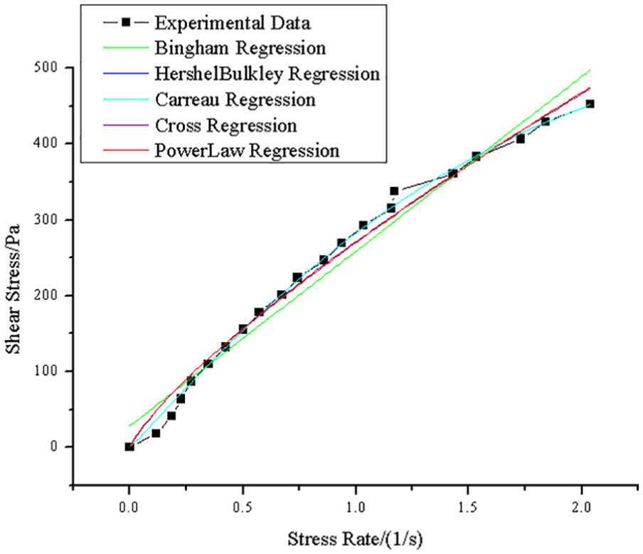
Rheological model fitting of ink at normal temperature.
Fitting of ink fluid model.

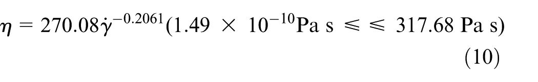
Because there are many parameters in the Carreau model, the relationship between the shear rate and the shear stress is more complicated and difficult to solve. Therefore, power law model is used to describe the ink fluid in this article. At normal temperature, the consistency coefficient k is 270.08 Pa s, and power law index n is 0.7939. To supplement the upper and lower limits of viscosity values,
On the basis of the data, the viscosity–shear rate model of the yellow offset ink studied in this article is as follows
The relationship between the viscosity and temperature of offset ink
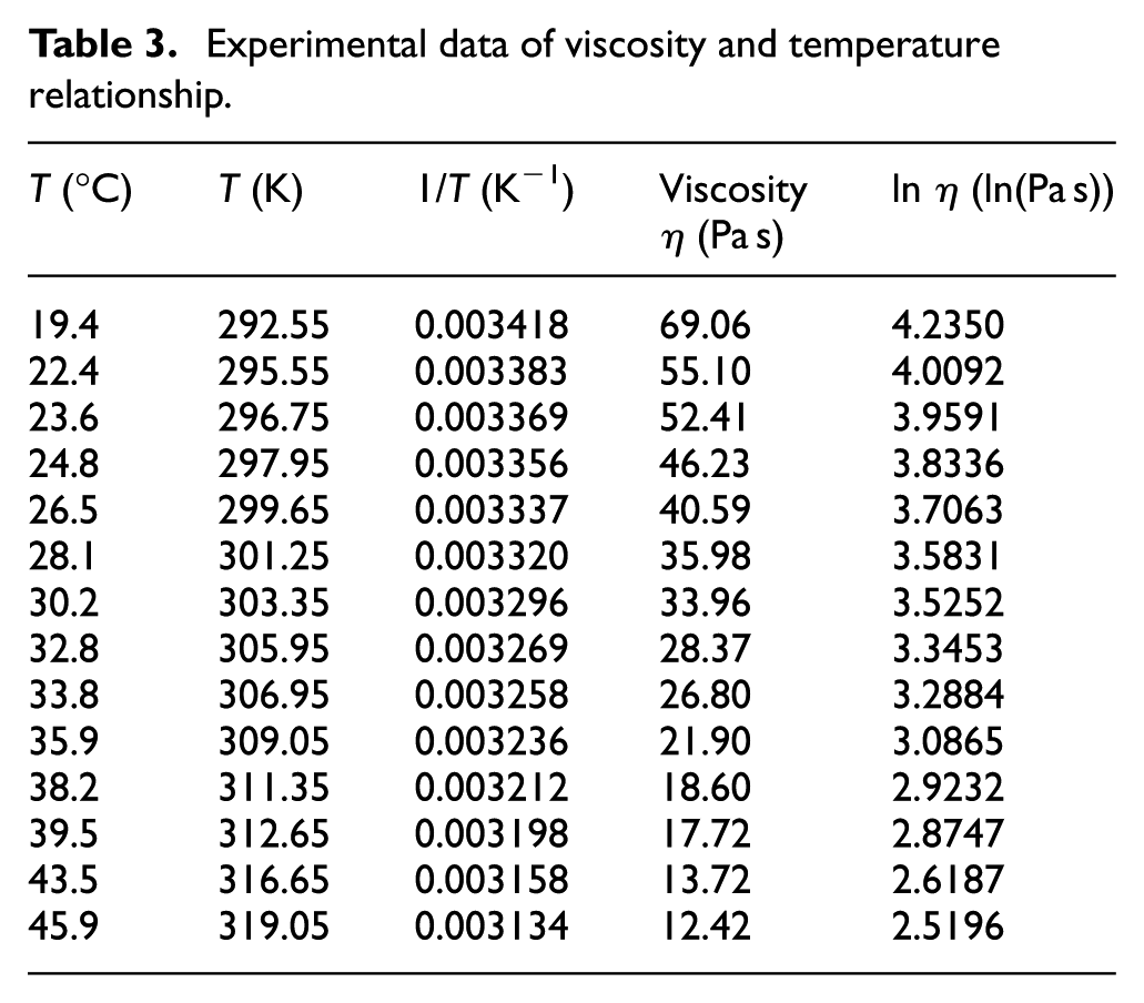
Zhang 15 and Versteeg and Malalasekera 20 indicated that the viscosity–temperature relation of offset ink can be expressed in formula (8). The viscosity of the yellow ink was measured at different temperatures. The relevant experimental data were shown in Table 3. The relationship between viscosity and thermodynamic temperature was obtained by refitting the data. The results were illustrated in Figure 2. The specific parameters were shown in Table 4.
Experimental data of viscosity and temperature relationship.

Relationship curve between the natural logarithm of the ink viscosity and the reciprocal of thermodynamic temperature.
Parameters after refitting; the given parameters are described in formula (8).

The relationship between the viscosity and the absolute temperature can be represented as follows
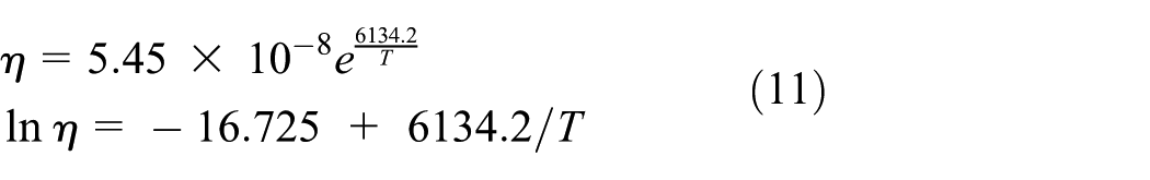
The experimental data of offset ink obtained in Zhang 15 were as follows: lnA: (–30.89) to (–16.1), Ea/R: 5506.17–10926.63. By comparison, it is found that the value of A and Ea/R in the viscosity-temperature relationship (equation (11)) is reasonable. Therefore, the viscosity–temperature relationship of offset ink can be represented in the upper form.
Mechanism of viscous dissipation and convectional heat transfer
Viscous dissipation effect
Viscous dissipation is the phenomenon that mechanical energy is transformed into thermal energy, which is caused by viscous friction in the process of fluid flow. It will lead to the change of the temperature and heat transfer behavior of the fluid during the flow process and then affect the fluid flow characteristics.5,21 Under the macroscopic view, the ratio of the surface area to the volume of the channel is small, and the shear strength of the fluid is weaker. Therefore, the viscous dissipation effect on the fluid flow is relatively smaller and can be ignored. But in the microscale, due to the decrease of the channel scale and the increase of the channel surface relative roughness and other factors, the velocity gradient along normal direction of channel wall increases. The shear force and friction resistance of the fluid also increases greatly, and the viscous dissipation effect strengthens. Thus, it leads to a significant change in the fluid flow characteristics in the microchannel.
Xu et al. 22 proposed that the temperature increases from the inlet to outlet of the microchannel was the most intuitive factor to weigh the strength of fluid viscous dissipation. The theoretical analysis was carried out by the Buckingham theorem and the dimensionless method. And the function that applicable to all shapes of channels and associated with temperature increase was obtained

In the formula, ΔT* is the dimensionless temperature, and its value is equal to the temperature increase of the fluid. A, a, b, c, and d are all undetermined constants. L and D are the length and equivalent diameter of the microchannel, respectively. L/D is the dimensionless length. Vi is the dimensionless viscosity. It indicates the size of the viscous dissipative energy, which is related to the fluid energy increase
There are eight parameters in the dimensionless parameters mentioned in formula (12), such as
Basic equations of convectional heat transfer
Convectional heat transfer involves the movement of the fluid, and the heat conduction and heat convection exist simultaneously. The convectional heat transfer equations include not only the energy conservation equation related to heat transfer, namely the differential equation of convectional heat transfer energy but also the mass conservation equation and momentum conservation equation, which related to momentum transport, namely continuity equation and N-S equation.
19
There are six related physical quantities in the convectional heat transfer, including three-dimensional (3D) velocity (u, v, w), pressure p, temperature T, and convectional heat transfer coefficient
In the process of convectional heat transfer, the heat transfer near the wall is shown in Figure 3. The conduction heat flux of the fluid at the wall is equal to that of the convectional heat flux.

Heat transfer near the wall in the process of convectional heat transfer.
According to Fourier law and Newtonian cooling formula, the local heat flux at the wall can be represented as

In the formula,

The upper formula is called the convectional heat transfer differential equation, which indicates the relationship between the convectional heat transfer coefficient and the fluid temperature field.
According to formulas (13) and (14), heat flux is related to heat transfer coefficient and temperature increase. It will form a closed equation set by combining heat transfer differential equation, mass equation, momentum equation, and energy equation. Therefore, heat transfer can be obtained by solving the temperature increase.
The basic analysis of the influence factors of the temperature field of offset ink
In the factors that affect the viscous dissipation, the channel scale and the fluid viscosity have great influence. The decrease of the channel scale and the increase of viscosity will increase the viscous dissipation. In the factors affecting the convectional heat transfer, the physical properties of the fluid and the shape and the material of the channel have some influence. When the fluid viscosity is greater, the flow boundary layer near the solid wall becomes thicker. Then the thermal resistance is greater, the obstruction of fluid flow and heat transfer becomes greater, and the effect of convectional heat transfer becomes weaker. The viscosity of the ink fluid decreases with the increase of temperature, which affects the heat transfer effect, and then affects the temperature change. Therefore, it is worthy to research the heat transfer of ink considering the viscosity–temperature relation.
Geometric modeling, grids division, and conditions setting
Geometric modeling and grids division
Two rollers are on the vertical arrangement. The upper one is a hard steel roller, and the lower one is a soft rubber roller. The diameters of the two rollers are both 50 mm. To simplify the analysis, the axial length of roller is set as 30 mm. Because the rubber roller deforms under two roller extrusion contact, and the center distance of two roller is set as 49.5 mm. Ink fluid adheres to the roller surface, and the ink layer thickness H0 is 0.5 mm. According to Versteeg and Malalasekera, 20 the ink channel height of the two roller extrusion zone is taken as the feature size. It can be set from 0.05 to 0.5 mm. The ink layer between two rollers was modeled by using the 3D drawing software UG. For the convenience of analysis, the model was divided into three parts, including non-extrusion zone, transition zone, and microchannel (extrusion zone). The result was shown in Figure 4. The “entrance” and “exit” of the microchannel were marked in the figure. The model is mainly applied to analyze fluid motion and heat transfer between a pair of hard roller and soft roller.
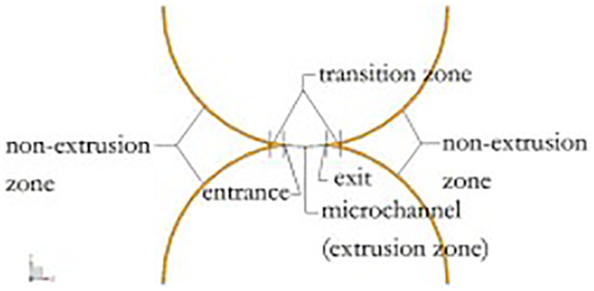
Ink model.
The parts were created by using mesh software ANSYS ICEM CFD. The steel roller wall and the rubber roller wall of the non-extrusion zone are denoted as “wall1” and “wall2,” respectively. The two roller walls of the extrusion zone are denoted as “wall4” and “wall3,” respectively. The inlet and outlet of the channel are denoted as “in” and “out,” respectively. The axial temperature of the extrusion zone basically remains unchanged. 12 Hence, two ends were set as symmetric plane and were denoted as “sym.” Finally, the structured hexahedral grid of the ink layer was obtained by dividing the grid, as shown in Figure 5. Among them, there are 100 nodes along the wall (wall1 or wall2) in X-Y plane in each part of the non-extrusion zone. In transition zone, there are 30 nodes in the X direction and 10 nodes in the Y direction in each part. In the extrusion zone, there are 200 nodes in the X direction. And the nodes along the Z axis are all 100. Besides, there are no negative volumes appearing in the grid. And the grid quality of all models was greater than or equal to 0.7.

Ink grid.
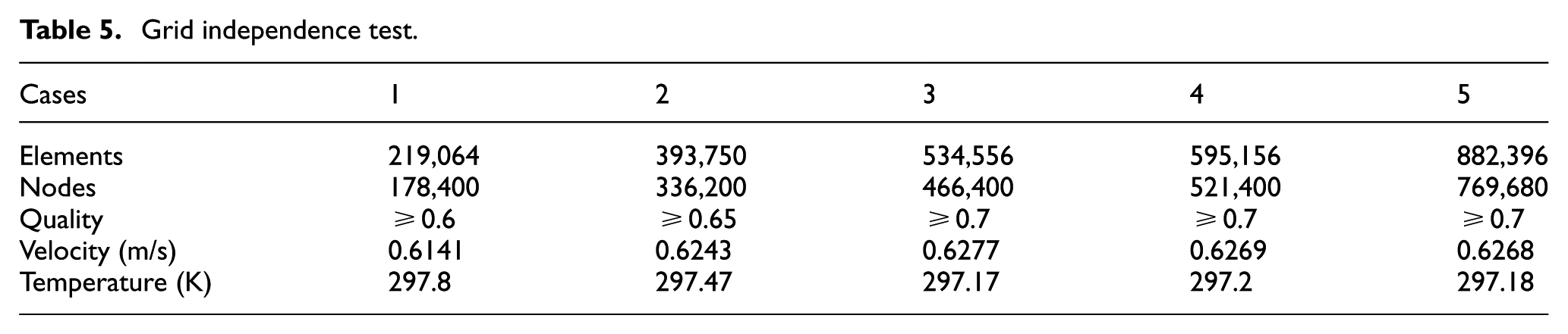
When the feature size was 0.8 mm, different grid was divided to verify grid independence. As shown in Table 5, the velocity and temperature on the point of (0, –25.04, 15) were extracted. Case 4 was adopted in the numerical models. The test results indicated that when the elements were greater than half a million or the grid quality was greater than or equal to 0.7, the grids were highly independent.
Grid independence test.
Basic assumptions
Based on the model, the steady analysis of the ink flow characteristics considering the heat transfer was carried out. The assumptions are as follows:
The effect of air flow and rubber roller heating on the flow characteristics and temperature field of the ink is not considered.
The effect of thermal radiation is negligible.
The effect of velocity boundary slip is negligible.
The ink viscosity is variable, and other physical properties are constant.
Model setting
The energy equation and the viscous heating option are activated. In the material setting, the fluid is ink, its density is 1012.985 kg/m3. The specific heat capacity is 1675 J/(kg K), and the thermal conductivity is 0.186 W/(m K). Non-Newtonian power law model is selected to describe the viscosity. Consistency coefficient k is 270.08 kg/(m s), and power law behavior index n is 0.7939. The maximum and minimum viscosities are 317.68 and 1.49 × 10⁻¹⁰ Pa s, respectively. The activation energy divided by the thermodynamic constant is 6134.2 K.
Boundary conditions setting
The inlet and outlet of the model are set as pressure-inlet and pressure-outlet, respectively, and the temperature is 293.15 K. The temperatures of two walls that are in contact with rollers are also 293.15 K. The heat transfer coefficient between the steel roller and ink is 301 W/(m2 K) and that between the rubber roller and ink is 162 W/(m2 K). The rotation speeds of the two rollers are 20 rad/s. The rotation direction of the upper one is anticlockwise and that of the lower one is clockwise.
The solution methods are default in FLUENT. The SIMPLE algorithm is adopted for model computation. The spatial discretization methods are as follows. Gradient is least squares cell based. Pressure is second order. Momentum is second-order upwind. Turbulent kinetic energy and turbulent dissipation rate are first-order upwind. The absolute criterion of energy residual is 1e–6 and for the others is 1e–3. The residuals converge within 200 iterations.
Results and discussion
Through the simulation analysis of the ink fluid, the ink temperature characteristics and the relationship between the characteristics and the feature size under the combined action of viscous dissipation and heat transfer were studied. The results were also compared with the ink temperature characteristic under the action of viscous dissipation.
Analysis of the ink temperature characteristics
The nephogram, a kind of contour map, represents the distribution of physical quantities with continuously changing color blocks. Figures 6–9 are the nephograms of the temperature, wall shear stress, pressure, and velocity of the ink fluid, respectively, whose feature size is 0.1 mm.
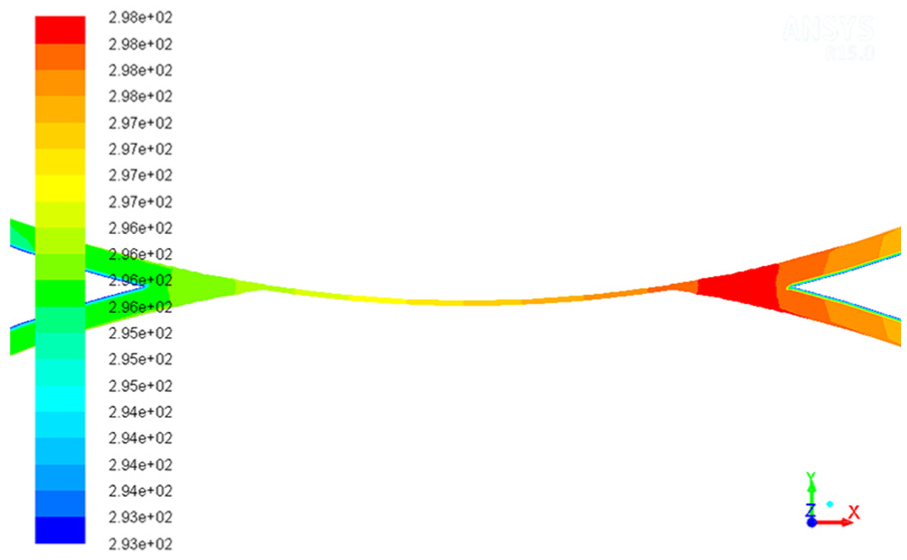
The nephogram of ink temperature.

The nephogram of ink wall shear stress.

The nephogram of ink pressure.

The nephogram of ink velocity.
As seen from the Figure 6, the maximum temperature appears near the exit of the microchannel, namely the transition zone between the microchannel exit and the non-extrusion zone. Experimental results by Huang 12 indicate that at the same rotating speed, the temperature in the extrusion zone of rollers increases fastest and first reaches the stable or upper limit value. The final temperature increase here is also higher than other zones, which is in agreement with the simulation results. Figure 7 shows that the maximum wall shear stress appears at the entrance and exit of the microchannel, namely the transition zone between the microchannel and the non-extrusion zone. Figure 8 shows that the maximum pressure appears at the entrance of the microchannel and its transition zone, and the minimum value occurs at the exit of the microchannel and its transition zone. Figure 9 shows that the maximum velocity appears in the middle of the ink layer along the thickness direction in the microchannel.
The maximum value of the wall shear stress appears in the transition zone between the microchannel and non-extrusion zone. Because the ink on both sides of non-extrusion zone converges to this position, the ink is subjected to larger extrusion, and there is a large velocity gradient between the ink layers inside the ink fluid. According to the formulas (1) and (10), the shear stress of the ink layers is high, so the shear stress between the ink layer and the wall is also high. Due to a sudden reduction of the size near the entrance of the microchannel, the ink is influenced by a stronger roller extrusion. Thus the maximum pressure appears at the entrance and transition zone. Similarly, the tension value in the exit and transition zone is the greatest. The ink has good fluidity under the driving of two rotating rollers; therefore, the maximum velocity occurs in the middle of the ink layer along the thickness direction of the microchannel.
The temperatures at microchannel entrance and exit are respectively denoted as Ten and Tex. The temperature increase, that is, the microchannel entrance temperature relative to the initial temperature is denoted as ΔTen. And the temperature increase, that is, the microchannel exit temperature relative to the entrance temperature is denoted as ΔTex. ΔTen = Ten – 293.15 K, ΔTex = Tex – Ten. The maximum temperature is denoted as Tmax. The temperature data were extracted and are shown in Table 6.
Ink temperature data.
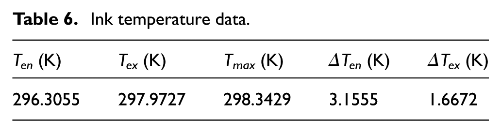
The length of the non-extrusion zone wall on the left side is 33.19 mm, and the length of the microchannel wall is 7.73 mm. It is known from Table 6, the unit distance temperature increase of the non-extrusion zone is 0.0951 K/mm, and the unit distance temperature increase of the microchannel is 0.2157 K/mm. The following conclusions are drawn from the data of Table 6.
Compared with the initial temperature of the model, the ink temperature at the microchannel entrance is higher because the ink layer attached to the roller surface generates heat due to the internal friction, and the heat transfer occurs between two walls and two rollers. But the heat transfer effect is weak. Due to the strong internal friction, the ink temperature increases in the flow process, which makes the temperature at the microchannel entrance higher than the initial temperature of the model. Huang 12 also indicates that along the circumferential direction of the ink roller, the temperature from the inlet to the extrusion zone gradually increases.
Compared with the ink temperature at the microchannel entrance, the ink temperature at the exit is high. The ink in the microchannel shows a stronger viscous dissipation due to the smaller size. The temperature increases in the flow process, which leads to the microchannel exit temperature increase. In addition, heat transfer between the two walls and the two rollers will lead to temperature decrease, but the heat dissipating capacity is less than the heat generation, the ink temperature in the microchannel increases finally.
The maximum temperature appears near the microchannel exit, namely the transition zone between the microchannel exit and the non-extrusion zone. The ink temperature at the microchannel exit increases under the effect of the viscous dissipation. With the ink flowing through the transition zone to the non-extrusion zone, the ink temperature is gradually reduced due to the weakening of the viscous dissipation. Therefore, the maximum temperature appears near the microchannel exit, and its value is slightly larger than the temperature at the exit. The location of the maximum temperature is basically the same as the position of the maximum wall shear stress and tension.
The temperature increase in microchannel is less than that of the non-extrusion zone, but the unit distance temperature increase of the former is larger than that of the latter. It shows that when the channel feature size is 0.1 mm, the decrease of the size makes the unit distance temperature to increase.
Analysis of the influence of feature size on the ink temperature characteristics
The feature size of the microchannel, namely the channel height, is recorded as H. The ratio of the microchannel height to the ink layer thickness (H0 = 0.5 mm) of the non-extrusion zone is defined as the channel scale coefficient, and it is recorded as δ, where δ = H/H0 (0 < δ ≤ 1). The corresponding relationship between the feature size of the microchannel and the channel scale coefficient is shown in Table 7.
The relationship between the feature size of the microchannel and the channel scale coefficient.

In the microchannel along the flow direction, the 11 equidistance points at the middle position of the ink layer are selected. When the channel height is less than 0.3 mm, the channel length decreases, and nine points are selected. These points are, respectively, represented by the angles that each point relative to the upper roller rotation center (260°, 262°,…, 280°) and recorded as X. The ink temperature of the microchannel along the flow direction under the different channel scale coefficients were extracted respectively. The results were shown in Figure 10. It is concluded that when δ is greater than or equal to 0.18, the lower the channel height, the faster the temperature increases in the extrusion area and the higher the temperature increase. 12
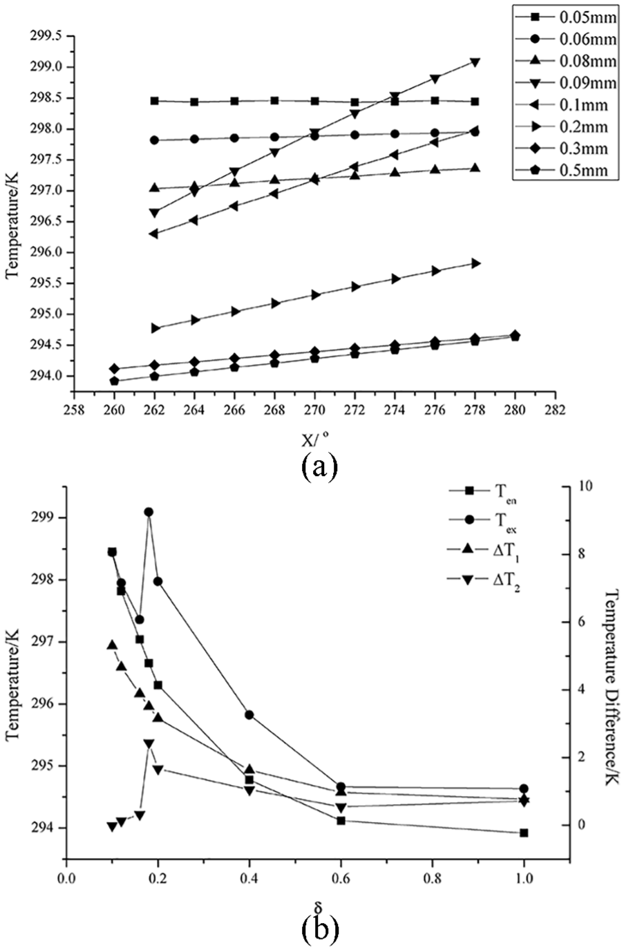
Curve of ink temperature along the flow direction under different channel scale coefficients: (a) curve of ink temperature along the flow direction and (b) curve of ink temperature at the entrance and exit of the microchannel.
Analysis of the temperature at the entrance of the microchannel
When the channel scale coefficient is smaller, the ink temperature at the microchannel entrance is greater. When 0.6 < δ ≤ 1, the temperature increase is small. When 0.2 < δ ≤ 0.6, the temperature increases in a certain range. And when 0 < δ ≤ 0.2, the temperature increase is higher. In the case of δ = 1, the temperature increase is the smallest, ΔTen|min = 0.7693 K, and when δ = 0.1, the temperature increase is the largest, ΔTen|max = 5.3013 K.
With the feature size of microchannel decreasing, the ink flow is gradually hindered, and more ink accumulates into the transition zone. The viscous dissipation effect of the ink obviously improves and the viscous heat generation increases. As a result, the ink temperature increases due to the high heat quantity. In other words, as the feature size decreases, the ink temperature increase becomes more. Besides, the viscous dissipation is greatly influenced by the size, especially when the size is less than 0.1 mm, the effect of viscous heat generation is stronger and the temperature increase becomes more.
Analysis of the temperature at the exit of the microchannel
When the channel scale coefficient is smaller, the ink temperature at the microchannel exit is greater. As the coefficient becomes smaller, the ink temperature increases at the microchannel exit relative to the entrance, increases first and then decreases, and is basically unchanged at last. When 0.6 < δ ≤ 1, the temperature increase is small; when 0.16 < δ ≤ 0.6, the temperature increase is higher; and when 0 < δ ≤ 0.16, the temperature basically has remains the same. In the case of δ = 1, the temperature increase is the smallest. And when δ = 0.18, the temperature increase is the largest, ΔTex|max = 2.437 K.
With the feature size of microchannel decreasing, the viscous dissipation effect of ink improves significantly, and viscous heat generation increases, resulting in increase of ink temperature. In other words, when the feature size is smaller, the temperature increase of the ink is larger. However, when the size reduces to a certain extent, especially less than 0.09 mm, more obvious temperature increase leads to the ink viscosity decrease (formula (10)). As a result, the viscous friction between the ink layers decreases. That is to say, the viscous dissipation weakens, and the smaller the size, the stronger the heat transfer. The stronger heat transfer takes away the heat quantity of the ink, thus making the temperature increase gradually decrease. When the size reduces to 0.05 mm, heat transfer and viscous dissipation are in dynamic equilibrium. The ink viscous heating is basically the same with heat transfer, which leads to the fact that the temperature in microchannel is basically no longer changing. Therefore, when the microchannel size is less than 0.09 mm, the temperature increase at the unit distance gradually decreases, and the enhancement of heat transfer is shown in the whole microchannel.
Analysis of enhanced heat transfer characteristics in microscale
The length of the non-extrusion zone wall on the left side is recorded as L0, which is 33.19 mm, and the length of the microchannel wall is L. The unit distance temperature increase is expressed as ΔTen/L0 and ΔTex/L, respectively. The unit distance temperature increase of the ink under different feature sizes are shown in Table 8. The relationship between the unit distance temperature increase of the ink and the channel scale coefficient was shown in Figure 11.
The unit distance temperature increase of the ink under different feature sizes.

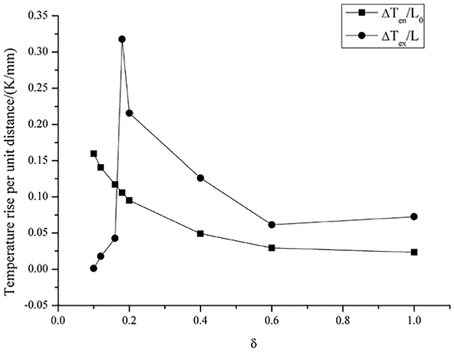
Relationship curve between unit distance temperature increase and channel scale coefficient.
Combined with Table 8 and Figure 11, we can draw some conclusions. The unit distance temperature increase of non-extrusion zone increases with the decrease of the channel scale coefficient δ. When δ = 1, the unit distance temperature increase of the non-extrusion zone is the smallest, which is 0.0232 K/mm. When δ = 0.1, the unit distance temperature increase of the non-extrusion zone is the largest, which is 0.1597 K/mm. With the decrease of the channel scale coefficient δ, the unit distance temperature increase of the microchannel increases first and then decreases. When the δ = 0.1, the unit distance temperature increase is the smallest, which is 0.0011 K/mm. When δ = 0.18, the unit distance temperature increase of the microchannel is the largest, which is 0.3177 K/mm.
When 0.1 ≤ δ ≤ 0.16, the unit distance temperature increase of the microchannel is obviously less than the non-extrusion zone. It indicates that the temperature increase is low when the microchannel size is too small. When 0.18 ≤ δ ≤ 1, the unit distance temperature increase of the microchannel is obviously larger than the non-extrusion zone. It is shown that because the microchannel size is less than the ink layer thickness in the non-extrusion zone, the temperature increases greatly in the microchannel and the heat transfer effect becomes poor.
Analysis of the maximum temperature
Figure 12 is the relationship curve between the ink maximum temperature and the channel scale coefficient δ. The ink maximum temperature is recorded as Tmax. As shown in figure, with the decrease of the channel scale coefficient, the maximum ink temperature gradually increases and then decreases, and increases at last. The trend of the maximum temperature is consistent with that of the microchannel exit temperature. The former is slightly higher than the latter (Figure 10(b)).

Relationship curve between the maximum ink temperature and the channel scale coefficient.
When 0 < δ ≤ 0.6, the temperature is large. When δ = 0.6 and δ = 1, the temperature is the smallest, which is 294.71 K. When δ = 0.18, the temperature is the largest, which is 299.46 K. When δ = 0.1, the temperature is the second largest, which is 299.28 K. When δ = 0.6 and δ = 1, the unit distance temperature increase of the non-extrusion zone is the smallest, so the temperature at the microchannel entrance is the smallest. Besides, the unit distance temperature increase of the microchannel is the smallest, so the temperature near the microchannel exit is the lowest. When δ = 0.18, the unit distance temperature increase of the microchannel is the largest; hence, the temperature near the microchannel exit is high in the case that the temperature at the microchannel entrance is high. When δ = 0.1, the unit distance temperature increase of the non-extrusion is the largest; hence, the temperature at the microchannel entrance is high. Therefore, even in the case that the unit distance temperature increase in the microchannel is the smallest, the temperature near the microchannel exit is still relatively high.
Analysis of the influence of heat transfer on the temperature and flow characteristics of ink
By comparing the ink temperature field under the interaction of viscous dissipation and heat transfer with the ink temperature field only under viscous dissipation, the influence of heat transfer on the ink temperature field and flow characteristics were analyzed. The ink temperature, velocity, pressure, and wall shear stress that are mentioned in this section are all the maximum values.
T 1, S1, P1, and V1 indicate the temperature, wall shear stress, pressure, and velocity, respectively, of the ink fluid between two rollers in the condition of heat transfer. In no heat transfer condition, they are denoted as T2, S2, P2, and V2, respectively. The differences of two conditions are denoted as ΔT = T2 – T1, ΔS = S2 – S1, ΔP = P2 – P1, and ΔV = V2 – V1. The ink temperature and flow characteristics under two conditions are shown in Figure 13(a)–(d). The left Y axis indicates the ink temperature, the wall shear stress, the pressure, and the velocity, and the right Y axis indicates the difference between the two conditions.
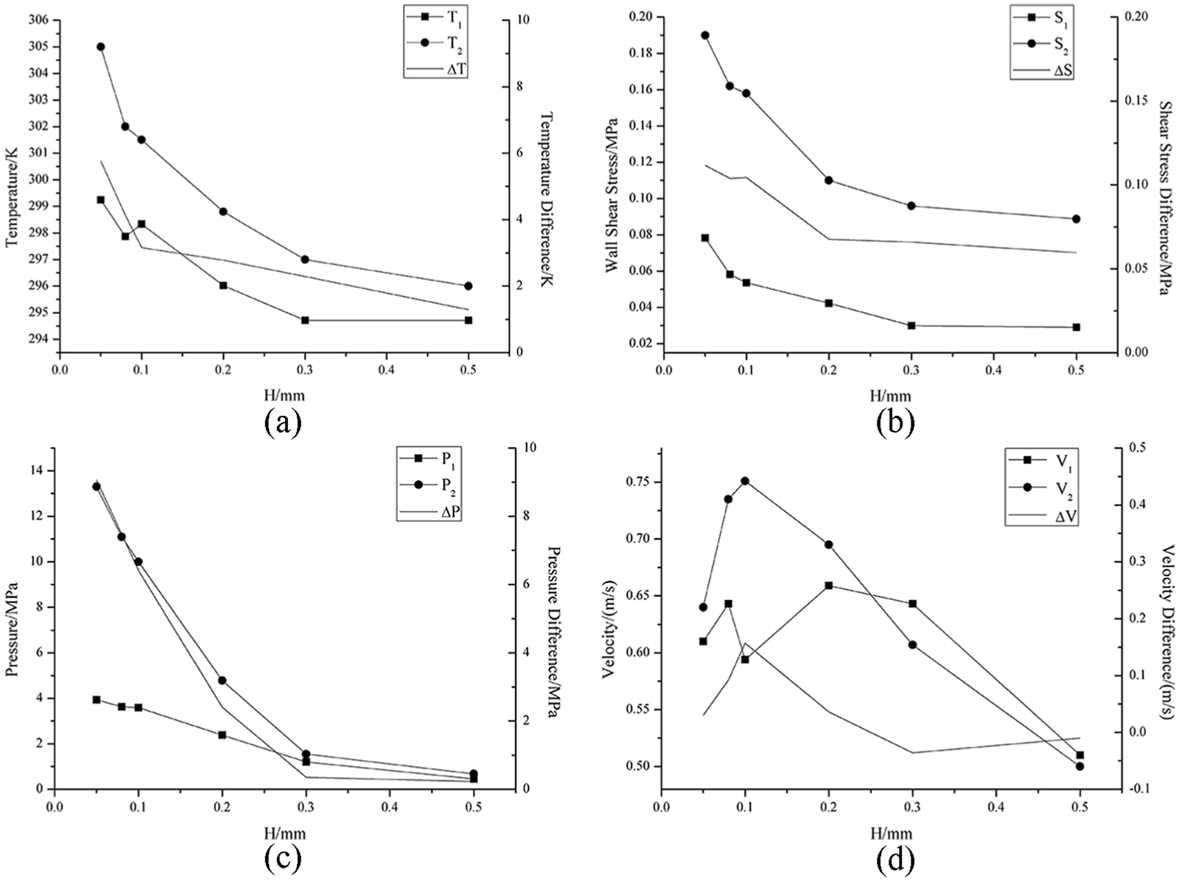
Contrast diagram of ink temperature and flow characteristics under two conditions of heat transfer and non-heat transfer: (a) ink temperature, (b) ink wall shear stress, (c) ink pressure, and (d) ink velocity.
With the feature size decreasing, the temperature, wall shear stress, and pressure under two conditions all increase, and the velocity increases first and then decreases. Compared to the condition only with viscous dissipation, the ink temperature, wall shear stress, pressure, and velocity under the interaction of viscous dissipation and heat transfer are lower. With the feature size decreasing, the differences of the ink temperature, wall shear stress, and pressure all increase more obviously. When the size is too low, the difference increases more significantly, and the velocity difference increases first and then decreases.
Figure 13(a) indicates that the heat transfer weakens the viscous dissipation effect and reduces the overall ink temperature. Under the interaction of viscous dissipation and heat transfer, the change of ink temperature is in dynamic equilibrium. In the case that the viscous heating is a fixed value, the heat transfer increases with the decreasing size. Especially, when the size is less than 0.1 mm, the heat transfer is greatly influenced by the feature size, and the fall of temperature results in the temperature difference increases more obviously. Therefore, with the size decreasing, the temperature difference is gradually increasing, and the trend becomes stronger when the size is too small.
Figure 13(b) indicates that the relative reduction of the viscous dissipation, namely the internal friction, leads to the wall shear stress decrease. With the feature size decreasing, the effect of heat transfer enhances. It makes the viscous dissipation become weaker and the wall shear stress decrease more. Thus the wall shear stress difference increases.
Under the heat transfer condition, the internal friction force between the ink layers decreases and the wall shear stress decreases, thus the ink pressure decreases, as shown in Figure 13(c). With the feature size decreasing, the extrusion between two rollers increases, so the ink pressure increases. While the heat transfer makes the pressure increase less, the pressure difference of the two conditions also increases with the decrease in size.
Figure 13(d) shows that under heat transfer condition, the ink pressure decreases, the overall ink flow speed decreases. As the feature size decreases, the ink velocity of two conditions increases first and then decrease, differing from under no heat transfer condition, the ink velocity under heat transfer condition increases first and then decreases after the decrease. This is due to the fluctuation of ink temperature when the size is small, which leads to the fluctuation of the ink velocity. When the size is 0.1 mm, the ink velocity considering heat transfer is the minimum value, and in no heat transfer condition, the ink velocity is the maximum value. Therefore, the velocity difference of two conditions is the maximum value at this size. As the size decreases, under heat transfer condition, the ink temperature increases slowly, the ink pressure also increases slowly, resulting in the ink velocity to increase slowly too. But when the size is too small, the ink flow is hindered and the velocity decreases. It means that the velocity difference between two conditions increases first and then decreases.
In conclusion, heat transfer makes the ink fluid’s overall temperature decrease, which further leads to the change of wall shear stress, pressure, and velocity. With the feature size decreasing, the heat transfer effect enhances.
Conclusion
In this article, non-Newtonian fluid characteristics of offset ink, including the viscosity–shear rate relationship and the viscosity–temperature relationship, were obtained by experiments. Then the steady flow and temperature characteristics of the ink fluid in the microchannel were analyzed on the conditions of viscous dissipation and heat transfer. The distribution of the temperature, shear stress, pressure, and velocity of the ink under the influence of different size was obtained. The influence of heat transfer was obtained by comparing with the condition without heat transfer. Through research and analysis, we got the following conclusions:
The viscosity–shear rate relationship and the viscosity–temperature relationship of offset ink can be well described by using the power law model and Arrhenius’s law, respectively.
Compared with the initial temperature, the ink temperature at the microchannel entrance is higher. Compared with the ink temperature at the microchannel entrance, the ink temperature at the exit is higher. The maximum temperature appears near the microchannel exit, namely the transition zone between the microchannel exit and the non-extrusion zone. The temperature increase in the microchannel is less than that in the non-extrusion zone, but the unit distance temperature increase of the former is larger than that of the latter.
The influence of feature size on the ink temperature characteristics is as follows. When the channel scale coefficient (feature size) is smaller, the ink temperature at the entrance of microchannel increases more obviously. Due to the increase of the hindering effect of the entrance on the ink flow, more ink accumulates in the transition zone, and the ink viscous dissipation is significantly enhanced. The viscous heating increases, resulting in more heat and a higher ink temperature, and the ink temperature at the exit increases, while decreases when the size is too small. Besides, the ink temperature increase from the microchannel entrance to the exit increases first and then decreases and keeps invariant at last because when the size is too small, heat transfer and viscous dissipation are in dynamic equilibrium. The viscous heating is basically the same as that of heat transfer, which leads to the fact that the temperature in microchannel is basically no longer changing, but the unit distance temperature of the microchannel decreases. Thus when the feature size is too small, the microchannel improves the heat transfer effect.
The effect of heat transfer on the ink temperature characteristics is as follows. The heat transfer makes the viscous dissipation weaken relatively and then the ink temperature decreases. Thus the wall shear stress decreases with the viscous friction decreasing, the ink pressure and velocity decreases. The heat transfer enhances as the feature size decreases.
Footnotes
Handling Editor: Oronzio Manca
Declaration of conflicting interests
The author(s) declared no potential conflicts of interest with respect to the research, authorship, and/or publication of this article.
Funding
The author(s) disclosed receipt of the following financial support for the research, authorship, and/or publication of this article: The project was supported by the National Natural Science Foundation of China (grant no.: 51675010), as well as Science and Technology Plan Project of Beijing Education Commission (grant no.: KM201710005015).