
Abstract
The error caused by measurement itself directly affects the accuracy of models. The error caused by the failure to follow the Bryan principle in the process of measuring the volumetric error of the machine tool makes the geometric accuracy of the machine tool after compensation less than the ideal effect. In this paper, it is proposed that the measurement error will be caused by the non coincidence of the measurement point and the tool position point in the measurement of linear axis error. According to Bryan principle, the relationship between the center point of the reflective mirror of the laser interferometer and the tool position point is analyzed. The straightness error produced in the measurement process is introduced into the volumetric error of the machine tool, and the geometric model containing the measurement error is established to improve the modeling accuracy of the machine tool. To prove the effectiveness of compensating measurement errors, an experiment has been conducted on a three-axis vertical machining center. The experimental results show that the geometric accuracy of the machine tool is improved by 23% after the measurement error is compensated.
Introduction
The measurement accuracy of machine tool is an important means to judge the overall accuracy of machine tool. The volumetric error of a three-axis machine tool is composed of 21 geometric errors (9 linear error motions, 9 angular error motions, and 3 squareness errors) in ISO 230-1: 2012. 1 These geometric errors can be detected by instruments according to the ISO 230-11 test codes. 2 Off-line identification of machine tool error parameters and establishment of volumetric error model have become the main research direction.
Most geometric errors can be measured directly by precise measuring equipment. 3 It is a simple and effective method to measure the geometric error of the rotating shaft by using the Double Ball-bar. 4 Laser interferometer is the most commonly used method to measure the geometric error of each axis of machine tool. 5 The R-test is used to measure the volumetric position of the rotating axis of the machine tool.6,7 The measurement method of trigger probe is also used to obtain the position information of X-, Y-, and Z-axis of machine tool. 8 The advantage of direct measurement is to obtain the actual error of the machine tool simply and quickly. Some scholars established geometric error models based on parameter terms measured directly. Huang et al. 9 identified two different geometric error for rotary axis based on the two error models. Maeng and Min 10 identified the geometric errors of rotary axis and set up error model using on-machine measurement. Chen et al. 11 identified the geometric errors parameters by analyzing the coupling relationship between the axes of the machine tool.
In the measurement process, the errors caused by different installation methods of instruments have the same order of magnitude impact on the measurement accuracy and error modeling of machine tools. The laser interferometer is often used as the measuring equipment to realize the direct measurement of geometric error. Its installation method is to fix the laser head on the worktable directly, and the reflective mirror is adsorbed on the side of the lower end of the spindle. The path of the effective point of a displacement measuring system should not be collinear with the path of the functional point whose displacement to be measured, which will produce Abbe error. 12 The target center of the laser interferometer reflective mirror should be located on the cutter position point. If it is impossible, the error caused by the angular movement of the worktable on the guide rail needs to be considered. 13 Bryan principle is widely used in precision machine tool measurement, and measurement error should also be considered in error modeling.14,15 The measurement error caused by the non-coincidence of measurement point and tool position point is amplified by the influence of angle error in the machine tool motion chain. 16 The Homogeneous Transformation Matrix (HTM) directly transforms the error offset from the starting position of each axis to the tool tip, which has some limitations.17,18 For the rotating axis, the coordinate transformation is not sensitive to the angle error, while for the straightness error of a single axis, it will vary with the deviation distance between the measuring point and the cutter position point.19,20
The model considering Bryan error in the measurement process is established in this paper, and the error is compensated, so as to further improve the geometric accuracy of the machine tool. Based on the traditional modeling and compensation, this method considers the straightness error caused by not following the Bryan principle in the measurement process. It is compared and verified that the influence of compensated measurement error on the geometric accuracy of machine tool.
The Bryan error during the process of measuring
The analysis of Bryan error
Laser interferometer is usually used to measure the geometric accuracy of machine tools. The arrangement of the measuring equipment is that the laser head is directly placed on the worktable, and the reflective mirror is adsorbed on one side of the lower end face of the spindle, as shown in the Figure 1. According to Bryan’s principle, if the cutter position point and the measuring point are not coincidence, and the angle error generate by the spindle box moving on the sliding guide rail will be amplified due to the deviation distance

The arrangement of laser interferometer.
The cutter position point is defined as point M and the measuring point is point N, and the volumetric position relationship of these two points is shown in Figure 2. The measuring point is selected as the datum point of the moving part, and the relationship between the straightness error of the cutter position point and the positioning error of the datum point conforms to the motion mode of the rigid body mechanical mechanism. Here, point N is used as the datum point of straightness error, so the straightness error of point M can be calculated from the offset of point N and the angle error of moving parts.

The volumetric position relationship of the cutter position and measuring point.
When the worktable moves along the X-axis, the straightness error of the cutter position point in the Y direction can be expressed as shown in equaiton (1).

Here,
Similarly, when the worktable moves along the X-axis, the straightness error of the cutter position point M in the Z direction will also be affected by the angle error and the datum straightness error. For the record,

It can be seen that the straightness error of cutting point M in Y direction will be affected by X direction offset distance, Z direction offset distance, pitch angle, and roll angle. Similarly, the straightness error in the Z direction is no exception. The specific expression is as follows:


Bryan error correction in geometric error measurement of linear axis of machine tool
When the laser interferometer is arranged on the worktable for straightness measurement, the angle error is also measured at the same time. Due to the existence of Bryan error, the measured angle error needs to be corrected. It is zero that the angle error and straightness error at the initial point. With the change of the coordinate position of the moving part on the coordinate axis, the straightness error and angle error are observed at this point. Taking the movement of the worktable along the X-axis as an example, due to Bryan deviation during measurement, the calculation formula for converting the angle error at this point into straightness error is as follows:


The error value is represented in the volumetric coordinate system, as shown in Figure 3.

Straightness error on X-axis.
Similarly, the calculation formula for converting the angle error of Y-axis and Z-axis into straightness error can be expressed as follows:


Due to the structure limitation of the measurement object, the layout of the measurement instrument can not meet the Abbe principle, which resulting in Abbe error when measuring positioning error. 21 It shows arrangement of reflective mirror does not meet the Bryan principle that the measuring point does not coincide with the cutter position point. Specifically, the measurement axis of straightness error is different from the reference axis of squareness error, which will produce straightness error.
The straightness of X-axis is defined as the datum, and the squareness error between the two axes is obtained by referring to the straightness of the X-axis when measuring the straightness of the Y-axis and the Z-axis. The straightness errors of X-axis and Z-axis measured by laser interferometer are

Squareness error of X, Z-axis.
When measuring the geometric errors of X-axis, Y-axis, and Z-axis, the measuring point N is defined as

Error deviation during measurement.
The full travel of the X-axis is

Due to the deviation between the measured track and the reference point, the corrected measurement results can be obtained by substituting the initial measurement point and the offset distance during measurement into the correction equations (14) to (16). It is as follows that the correction formula of measurement error caused by the measuring point does not coincide with the cutter position point when measuring X-axis.

When measuring Y-axis and Z-axis, the measurement error correction formula caused by non-collinearity is as follows:


Where

The space decomposition of squareness error.
The measurement error still exists when measuring the squareness error. The measurement result of squareness error needs to be correct by the deviation angle caused by measurement deviation. The correction value of squareness error of X-axis relative to Y-axis and Z-axis is as follows:


Similarly, the correction value of squareness error of Y-axis relative to Z-axis is as follows:

Thus, the corrected squareness error is as follows:


The geometric errors of three-dimensional space of NC machine tools include positioning error, straightness error, angle error (pitch, yaw, roll), Abbe error, Bryan error, and squareness error.
Modeling of volumetric error
Due to the non coincidence of cutter position point and measurement point the measurement error is caused in the process of measurement. Therefore, the influence of the Bryan error on the error compensation effect of the machine tool needs to be considered in the process of error modeling.
Transmission of Bryan error in three dimensional space
Due to the Bryan error value generated in the measurement process the measurement instrument itself cannot obtain the measurement error value. Therefore, HTM modeling cannot directly calculate the accurate volumetric error value from the measured value. In the process of measuring the machine tool accuracy, the Bryan error has changed significantly on the motion chain of each axis of the machine tool due to the movement of moving parts. When the moving distance of the worktable is

When measuring the straightness error caused by the movement of the worktable along the X-axis, N sampling points are taken, and the ith point is taken as the state observation point. After the observed linear error is transferred to the cutter position point, the error value of the point is changed. The calculation formula is as follows:

Here,
Similarly, when the worktable moves along the Y-axis, the solving formula of the tool position error is as follow:

When the spindle box moves along the Z-axis, the solving formula of the tool position error is expressed as follow:
HTM model based on Bryan error
The traditional homogeneous coordinate transformation calculation method can not directly calculate the final machine tool volumetric error from the measured value of machine tool. The same error expression result as that of the error vector transfer method can be obtained by using the non collinear error correction formula. The deviation between the cutter position point and the measuring point will reflect the position of the laser transmitting point, which result in the measurement error from the laser transmitting module. In order to obtain higher precision compensation effect, the compensation model with measurement error needs to be considered. The essence of the error includes the geometric error of the machine tool itself and the measurement error generated in the measurement process. The superposition of the two errors makes the relative position of the tool and the worktable deviate further from the set position. Aiming at the position relationship of the tool position point relative to the measuring point, the error model is established as follows:


Experiment
In order to prove the influence of Bryan error on the compensation effect of machine tool, a three-axis vertical machining center is adopted as the measuring object. The size of machine tool table is 300 mm × 300 mm. The ambient temperature of the experiment is controlled at 25.0°C ± 0.1°C. The travel of the machine tool in the X, Y, and Z directions are as follows:
X-axis: 350 mm; Y-axis: 210 mm; Z-axis: 260 mm.
Verification experiment of Bryan error
In order to prove the influence of Bryan error generated in the measurement process on the volumetric accuracy of the machine tool, a laser interferometer, XM-60 by Renishaw Co. Ltd, is placed on the worktable. The instrument’s resolution is 1 nm, and the accuracy of straightness measurement is ±0.5 ppm, and the range of straightness measurement is −250 to 250 μm. The range of angle measurement is −500 to 500 μrad. The reflective mirror is mounted on the 140, 240, and 360 mm away from the cutter position point on the front of the spindle box respectively, and then the straightness error of the three axes is measured, as shown in Figure 7.

The deviation between measuring point and cutter position point: (a) deviation distance: 140 mm, (b) deviation distance: 240 mm, and (c) deviation distance: 360 mm.
Comparative experiment after compensating Bryan error
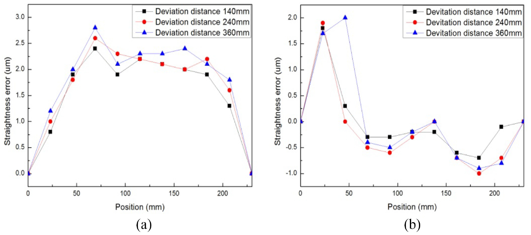
The straightness error of the worktable moving along the X-axis in the Y direction is different at different deviation positions, as shown in Figure 8(a). The maximum straightness error generated is −1.8 μm when the measuring point deviates from the cutter position point by 140 mm. It is −2.0 μm that the maximum straightness error generated when the measuring point deviates from the cutter position point by 240 mm. It rises to −2.4 μm that the maximum straightness error generated when the measuring point deviates from the cutter position point by 360 mm. The maximum straightness error in the Z direction increases from −1.3 to −1.9 μm, as shown in Figure 8(b).

The worktable moving along the X-axis: (a) The straightness error in the Y direction and (b) The straightness error in the Z direction.
In the same way, it is measured that the straightness errors of the worktable moving along the Y direction and the spindle box moving along the Z direction. The measurement results are shown in Figures 9 and 10. When the deviation change between the measuring point and the cutter position point is 140–360 mm, it increases from 2.2 to 2.8 μm that the maximum straightness error of the worktable moving along the Y-axis in the X direction. When the spindle box moves along the Z-axis, the straightness error in the Y direction increases from −1.3 to −2.4 μm with the increase of the deviation distance. The vertical deviation error of X-axis relative to Y-axis increases from 17 to 35 μrad. The vertical deviation error of X-axis relative to Z-axis increases from 32 to 105 μrad. The vertical deviation error of Y-axis relative to Z-axis increases from 52 to 87 μrad.
The worktable moving along the Y-axis: (a) The straightness error in the X direction and (b) the straightness error in the Z direction.

The spindle box moving along the Z-axis: (a) The straightness error in the X direction and (b) the straightness error in the Y direction.
It can be seen from this that the measurement results will be different when the reflector of the laser interferometer is set at different positions. When the worktable moves along the X-axis, the maximum straightness error increases by 32% as the distance increases between the measuring point deviates from the cutter position point. Similarly, the maximum straightness error increases by 21% when the worktable moves along the Y-axis. The maximum straightness error increases by 46% when the spindle box moves along the Z-axis, and the average straightness error is increased by 33%. The closer the measurement point is to the cutter position point, the smaller the measurement error is, and vice versa.
According to the measurement results caused by the deviation of 140 mm as an example, the straightness error caused by the measurement is solved by using the straightness error formula (7) to (12), and then the straightness error of each axis is measured again after error compensation. The comparison before and after compensation is shown in Figure 11.

The straightness error comparison: (a) the worktable moves along the X-axis, (b) the worktable moves along the Y-axis, and (c) the spindle box moves along the Z-axis.
Table 1 shows the maximum straightness error comparison data generated in each moving direction. Compared to the straightness error before and after compensation, the geometric accuracy of the machine tool is improved by compensating the straightness error caused by measurement. The effect of the vertical deviation error of X-axis relative to Y-axis is not obvious after compensation, but the vertical deviation error of X-axis relative to Z-axis decreases from 105 to 30 μrad, and the vertical deviation error of Y-axis relative to Z-axis decreases from 87 to 18 μrad after compensation.
Maximum straightness error before and after compensation.

Conclusion
The straightness error is caused by non coincidence of reflection point and cutter position point when the reflector of laser interferometer is erected. Due to the limitation of machine tool structure, the actual measurement does not meet the Bryan principle, which result in straightness error. In this paper, it is analyzed that the measurement error caused by the non-conformity between the measuring point and the tool point when the instrument is erected. The error model is established by modifying the measurement error generated by the actual erection. The straightness error of each axis of the machine tool will decrease by 11% on average after compensating the straightness error generated in the measurement process. The experimental results show that it is feasible to modify the measurement error and improve the modeling accuracy.
When measuring the relative position between the worktable and the guide rail, whether the error data comes from the gap between them or the contact deformation is not further subdivided. On line measurement and compensation of sub items under complex processing conditions is a problem to be studied in the future.
Footnotes
Handling Editor: Chenhui Liang
Author contributions
HL performed the methodology research and formal analysis and wrote the manuscript. RY performed the measurement experiment and data analysis.
Declaration of conflicting interests
The author(s) declared no potential conflicts of interest with respect to the research, authorship, and/or publication of this article.
Funding
The author(s) disclosed receipt of the following financial support for the research, authorship, and/or publication of this article: This research was supported by China’s national major science and technology project (grant no. 2019ZX04001024).
Ethics approval
This paper is compliant with all ethical standards.
Consent to participate
All the participants provided informed consent.
Consent for publication
Informed consent for publication was obtained from all participants.
Code availability
The code generated or used during the current study is available from the corresponding author upon reasonable request.
Data availability
The datasets used or analyzed during the current study are available from the corresponding author upon reasonable request.