
Abstract
The nonlinear factors in the digital hydraulic cylinder will reduce the accuracy of the control system. In order to improve the control accuracy of the control system, in this paper, a model reference adaptive disturbance rejection control method based on neural network is proposed. Firstly, the dead zone model is used to replace the nonlinear link in the feedback mechanism. A detailed mathematical model of digital hydraulic cylinder is established and the nonlinear hydraulic spring force is also considered, and a complete nonlinear state space model of digital hydraulic cylinder is derived based on LuGre friction model. Then the reference model is designed. By introducing ESO (extended state observer), the uncertainties and external disturbances of the controlled object are all equivalent to a total disturbance. The RBF (Radial Basis Function) network is used to approximate the unknown function FZ, the neural model reference adaptive disturbance rejection composite controller is designed by using Lyapunov direct method and Barbalat lemma. Finally, the simulation verification is carried out by using MATLAB. The simulation results show that the control strategy can effectively improve the response characteristics of the system, reduce the steady-state error of the system, and improve the robustness of the system.
Keywords
Introduction
Digital hydraulic cylinder has great potential in current engineering application because of its simple structure, strong anti-pollution ability to oil and high positioning accuracy. 1 There are multiple clearance links in the feedback device of the digital hydraulic cylinder. These clearance links will not only reduce the rapidity and stability accuracy of the system, but also make the system generate self-vibration, which will affect the normal operation of the system more seriously and cause system damage. 2 At the same time, there is an asymmetric hydraulic cylinder structure in the digital hydraulic cylinder, which will also cause serious asymmetry of the system and seriously affect the tracking accuracy and stability of the system.3,4 Therefore, the establishment of a relatively accurate mathematical model of the digital hydraulic cylinder is of great significance to the study of the nonlinear dynamic characteristics of the system.
At present, scholars have done a lot of research on the nonlinear characteristics of clearance. In Wen and Zhou, 5 nonlinear links such as clearance and dead zone are considered as bounded disturbances. Adaptive backstepping method is used to design compensation controller, which is easy to cause “digital explosion” of control system. In Zijie et al., 6 in order to overcome the backstepping “digital explosion” problem and the filter error problem, a feedforward controller is designed by combining the command filtering technology and the backstepping method. At the same time, the single network online approximation is used to solve the approximate optimal controller, which makes all the signals in the closed-loop system bounded and ensures the stability of the system. Chi and Ma 7 studied the gap nonlinear limit cycle oscillation phenomenon in the full closed-loop servo system, designed the state feedback compensation suppression strategy, and designed the feedback compensation coefficient by using the pole assignment method to suppress the limit cycle oscillation phenomenon. The simulation and experimental results show that the control strategy can improve the control accuracy of the system. Li et al. 8 proposed a new composite robust control strategy consisting of output feedback and gap dynamic inverse compensation for Wiener-Hammerstein system with asymmetric gap, which realized the compensation of model error and ensured that the tracking error of the system converged to any small neighborhood around the origin. Zheng and Zhang 9 designed a neural network adaptive control strategy for the uncertainty of actuator clearance and bounded disturbance, and designed an adaptive control scheme using the backstepping method. The adaptive control law is updated by an adaptive execution – evaluation structure network. This control scheme can ensure the stability of the closed-loop error system in the sense of uniform ultimate boundedness. The simulation results show the effectiveness of the control method; in Yang and Tan, 10 aiming at the problems of uncertainty and disturbance in valve-controlled asymmetric hydraulic cylinder system, feedback linearization control is used to improve the control accuracy of nonlinear system, variable structure control is used to compensate external interference and system uncertainty, and boundary layer method is used to reduce the sliding mode variable structure control may lead to high frequency chattering of the system. A composite control strategy of robust feedback linearization is proposed. The experimental results show that the robust feedback linearization strategy can effectively suppress the influence of external interference and load disturbance on the accuracy of hydraulic position tracking, and improve the accuracy and robustness of hydraulic control system. However, this control strategy is only applicable to low-order systems; in Sun et al., 11 model predictive current control (MPCC) is used. In order to enhance the robustness of the control system, sliding mode controller is used to replace the traditional PI speed loop, and a finite position phase-locked loop based on dichotomy is added to achieve sensorless speed control and provide accurate rotor position angle. Simulation and experimental results show the effectiveness of the proposed MPCC scheme and its steady-state performance. In Li et al., 12 in order to solve the problem of complex downhole environment and serious electromagnetic interference, it is not suitable to install position sensors and other precision devices. A sensorless control method of permanent magnet synchronous motor (PMSM) for submersible pump is proposed. The three-level inverter is used to provide energy for the submersible pump of the permanent magnet synchronous motor through a long power cable. Compared with the two-level inverter, it can effectively suppress the over-voltage of the motor terminal, effectively reduce the heat generated by the motor, and reduce the energy consumption during oil production. Therefore, using sensorless control can achieve high-precision control system. In Zhongshan et al. 13 proposed an adaptive friction compensation method based on LuGre model and observer/filter structure, and verified the tracking performance of this method through simulation. Ming et al. 14 designed a linear robust observer for the valve-controlled asymmetric cylinder electro-hydraulic servo system, which can only ensure the robustness of the system under small load. Yan et al. 15 indicate that the observer-based method does not eliminate the existence of model bias. It should be noted that eliminating model deviations is always the ultimate goal and reason for robust controller design. In Tian et al., 16 for the problem of disturbance rejection and output feedback control of nonlinear friction, an adaptive neural network sliding mode control is proposed by using the state expander to obtain the state signal of the system. This control algorithm has simple structure and less design parameters, but it has high requirements for the initial value of the state observer. Guo et al. 17 proposes an adaptive robust control strategy based on LuGre friction model, which includes model compensation, stable feedback and robust control. Lyapunov stability method is used to prove the signal boundedness of the closed-loop control system, and the dynamic and steady-state tracking errors can be within the desired range by adjusting the controller parameters. Both theoretical analysis and simulation studies verify the effectiveness of the method. Sun et al. 18 proposed a novel FCS-MPCC (finite-control-set model predictive current control) without a modulator to drive permanent magnet synchronous hub motors (PMSHMS), which combines virtual vectors expansion scheme and duty cycle control was proposed. The deadbeat principle is used to obtain the reference voltage for determining the sector. Then, the best voltage vector in the selected sector is determined by the predetermined cost function. The new algorithm can reduce the computational burden. In addition, this method avoids the use of additional modulators and reduces the complexity of the control system. At the same time, it can effectively reduce torque ripple and improve current harmonic without slowing down dynamic response. Sun et al. 19 proposed a model predictive current control (MPCC) compensation method based on virtual voltage vectors for single-phase open-circuit faults of an asymmetric six-phase permanent magnet synchronous hub motor (PMHSM). Then these 64 voltage vectors are appropriately compensated and synthesized into 24 new virtual voltage vectors. Then, the same decoupling transition in the healthy state can still be used for fault-tolerant operation without the need to reconfigure the controller structure. Experimental results prove the effectiveness of the method before and after fault tolerance and provide satisfactory steady-state and dynamic performance. Zhu et al. 20 explored the influence of nonlinear hydraulic spring force on the dynamic characteristics of electro-hydraulic servo system. It is pointed out that the nonlinear hydraulic spring force can be described by Duffing equation. Through in-depth analysis of the measured data, the jump phenomenon caused by the soft and hard spring characteristics of the hydraulic spring is revealed. It is found that the nonlinear effect of hydraulic spring force will cause nonlinear vibration, and its nonlinear effect should be taken into account in system modeling and dynamic characteristics research.
The above literature only studies the influence of clearance nonlinearity, friction nonlinearity, and nonlinear hydraulic springs on the system performance, and then uses different control strategies to improve the system performance, and studies low-order systems. At present, there is no literature on the unified study of digital hydraulic cylinder clearance, friction, and nonlinear hydraulic spring.
This paper first studies the working principle of digital hydraulic cylinder, establishes the servo motor model, uses the dead model to establish the dynamic model of the feedback mechanism, the asymmetric hydraulic cylinder model controlled by the four-side valve, the LuGre friction model, and the nonlinear hydraulic spring model, and finally establishes the nonlinear state space model. Then a reference model is designed to enhance the adaptability of the digital hydraulic cylinder position control system. ESO (extended state observer) is introduced to the uncertainty of the controlled object and the external disturbance is equivalent to a total disturbance, and the disturbance estimation is used as a feedforward compensation. ESO is more convenient, predictive, flexible, and robust. Therefore, ESO is selected as the observer in this paper. Due to the inaccurate state estimation and other factors, the observation error is induced in the process of system observation. In order to solve this problem, RBF network is used to approximate the unknown function FZ, and the neural model reference adaptive disturbance rejection composite controller is designed by Lyapunov direct method and Barbalat lemma. Finally, the effectiveness of the proposed control method is verified by simulation experiments. Finally, the simulation verification is carried out by using MATLAB. The simulation results show that the control strategy can effectively improve the response characteristics of the system, reduce the steady-state error of the system, and improve the robustness of the system.
Working principle of digital hydraulic cylinder
This paper studies the digital hydraulic cylinder in the form of internal indirect feedback, and its principle structure is shown in Figure 1. The internal indirect feedback mechanism is composed of ball screw and valve core feedback mechanism. The ball screw is supported by the bearing on the cylinder head, which can only rotate circumferentially and cannot move axially. Eight in Figure 1 shows that the piston thread pair is formed between the screw and the piston. Five in Figure 1 shows that the feedback nut is connected with the thread of the valve core to form the valve core thread pair. The coupling connects the output shaft of the servo motor with the spool. The spool can move axially and rotate circumferentially relative to the motor shaft, forming the spool sliding pair.

Working principle diagram of digital hydraulic cylinder. 1. Servo motor; 2. Coupler; 3. Valve body; 4. Spool; 5. Spool thread pair; 6. Fixed sleeve; 7. Thrust bearing; 8. Piston thread pair; 9. Ball screw; 10. Piston; 11. Cylinder body.
When the command signal of the system is zero, the servo motor stops, the valve core is at zero position. Under the control of the zero-opening four-side sliding valve, the pressure of the two chambers of the hydraulic cylinder remains balanced, and the piston rod stops. When the command signal is positive, the potential difference between the displacement sensor and the instruction signal potentiometer (reflecting the deviation between the position of the control object and the position of the instruction signal) is input into the servo motor through the controller. The servo motor drives the valve core to rotate clockwise. Under the action of the screw nut pair at the end of the valve core, the valve core moves along the axial direction, so that the valve opening is opened. The pressure in the rod cavity of the hydraulic cylinder increases, the pressure in the rodless cavity decreases, and the piston and piston rod shrink back. The screw rotates under the side effect of the piston thread, and the feedback nut rotates clockwise. Under the action of the spool thread pair, the spool moves backward, and the valve port begins to decrease. When the piston retracts a certain displacement, the rotation angle of the feedback nut is the same as that of the spool (i.e. the motor rotation angle). The valve port is closed, and the piston and piston rod stop moving, and the deviation is zero at this time. When the command signal is negative, it is opposite to the above motion. Thus the position of the control object is always changed according to the law given by the command potentiometer.
Nonlinear state space model
Firstly, the mathematical model of servo motor, the dynamic model of feedback mechanism, and the mathematical model of asymmetric hydraulic cylinder controlled by four-side valve are established. Then, the nonlinear state space model of digital hydraulic cylinder is established, which is the basis for the design of system controller.
Mathematical model of servo motor
AC permanent magnet synchronous motor is equivalent to DC motor under vector control,21,22 and its physical model is shown in Figure 2.
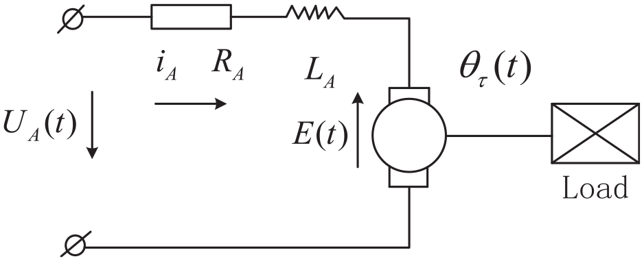
Physical model of permanent magnet synchronous motor.
According to the working principle of the motor,23,24 the motor rotation generates torque
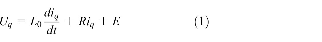
In the formula:
According to the dynamic principle, the torque balance equation on the motor shaft is:

In the formula:
Dynamic model of feedback mechanism
The dynamic model of the digital hydraulic cylinder system is shown in Figure 3. The clearance is mainly in the spool sliding pair, spool thread pair, and piston thread pair. As can be seen from Figure 3, that the three gaps in the forward and feedback loops will cause the response delay of the system and affect the stability of the closed-loop system. When the gap is unreasonable, the system may oscillate and even cause the system to fail to operate normally.

Dynamic model of digital hydraulic cylinder system.
Figure 3 establishes the nonlinear dynamic model of digital hydraulic cylinder feedback mechanism, and then further analyzes the influence of clearance on closed-loop control. The contact surfaces of each connection pair can be equivalent to a spring-damping model, and the stress analysis of spool thread pair and screw thread pair is also marked in Figure 3. The arrow in the figure indicates a positive direction.
Since the follower of the system has small inertia and friction, the follower has small damping characteristics,
25
so it quickly crosses the gap and contacts with the follower under the control signal of the active component. Therefore, dead-zone clearance model is most suitable for describing the clearance nonlinearity in digital hydraulic cylinder system. Therefore, the gap nonlinearity contained in this paper is studied by the dead-zone gap nonlinear model. The input and output curves of the dead model are shown in Figure 4. The length of dead zone

The nonlinear model of dead zone gap.
Modeling of spool sliding pair
The motion relationship of the sliding pair of the valve element is that the motor shaft is the input end and has only one rotation degree of freedom. It drives the valve element at the output end to rotate through the sliding pair. The valve element can move along the axial direction of the sliding pair while rotating. The valve element has two degrees of freedom: circumferential rotation and axial movement. The input of the sliding pair is the rotation angle of the motor shaft and the output is the rotation angle of the valve element. The normal relative displacement of the adjacent contact surface of the sliding pair of the valve element is:

In the formula:
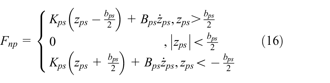
Ignoring the circumferential friction between the motor shaft and the spool when the motor shaft rotates in the gap, therefore assuming that the spool will be subjected to torque only when the relative displacement is greater than half of the maximum width of the gap. The normal force of the adjacent contact surface of the sliding pair of the valve element:

In the formula: the stiffness and damping of the contact surface are
Since the axial movement of the valve element causes the two contact surfaces to move tangentially relative to each other after the adjacent contact surfaces of the valve element sliding pair are combined, the friction problem is relatively complicated. Here, the Coulomb static friction model is adopted (the following friction models are adopted), and the friction force of the adjacent contact surfaces of the valve element sliding pair is:

In the formula:
Modeling of spool thread pair
The motion relationship of spool thread pair is that the spool has two degrees of freedom of rotation and axial movement, while the screw has only one degree of freedom of rotation. Whether the spool rotation or the screw rotation, the spool will produce axial movement. The input of the thread pair is the difference between the spool and the screw rotation, and the output is the axial displacement of the spool. There is a gap between the adjacent tooth surfaces of the spool thread pair. It is assumed that the initial position of the inner thread of the spool is in the middle of the gap. When the distance between the outer thread of the spool and the adjacent tooth surfaces of the inner thread of the screw decreases to zero with the increase of the angle difference between the spool and the screw, the two tooth surfaces begin to contact, produce normal binding force

In the formula:
Normal force between adjacent tooth surfaces of spool external thread and screw internal thread is:

In the formula: the maximum width of the gap is
The relative tangential displacement between the adjacent tooth surfaces of the spool external thread and the screw internal thread:

Normal friction force between adjacent tooth surfaces of outer spool thread and inner screw thread

In the formula:
The force acting on the spool, in addition to the above force from the spool sliding pair and spool thread pair, also includes the hydrodynamic force acting on the spool. According to Wang et al., 26 it is called hydrodynamic force. The hydrodynamic force includes steady-state hydrodynamic force and transient hydrodynamic force, in which the steady-state hydrodynamic force is proportional to the spool opening amount, and the transient hydrodynamic force is proportional to the change rate of spool opening amount. The steady-state hydrodynamic force is:

Transient hydrodynamic force is
Therefore, the hydrodynamic force acting on the valve core is:

In the formula,
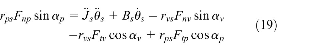
Therefore, the torque balance equation of spool rotation is

In the formula:
The force balance equation of spool axial translational motion is:

Formula:
Modeling of piston thread pair
The piston and screw are the input and output ends of the piston screw pair, respectively. The piston has one axial movement degree of freedom, and the screw has one rotational degree of freedom. When the piston moves axially driven by hydraulic force, the screw rotates through the screw pair. It is assumed that the initial position of the internal thread of the piston is in the middle of the clearance. When the distance between the external thread of the screw and the adjacent tooth surfaces of the internal thread of the piston decreases to zero with the axial movement of the piston, the two tooth surfaces begin to contact, the normal binding force

where
In the formula, the maximum width of the gap is
The tangential relative displacement between the adjacent tooth surfaces of screw external thread and piston internal thread:

Friction force between adjacent tooth surfaces of screw external thread and piston internal thread

In the formula:
Therefore, the torque balance equation of screw rotation is
Mathematical model of asymmetric hydraulic cylinder controlled by four side valve
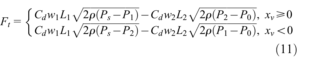
The working principle of symmetrical four-side sliding valve controlling asymmetric hydraulic cylinder is shown in Figure 5.27,28 It can be seen from Chen et al. 24 that the linearization form of the flow and pressure characteristics of the valve in the positive and negative directions can be uniformly expressed as:

In the formula:
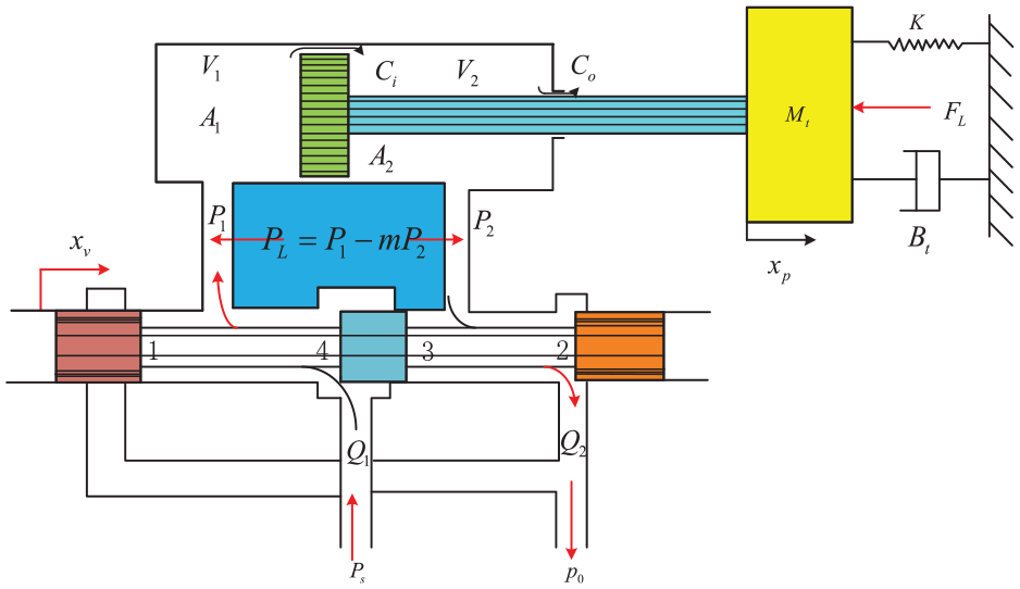
Schematic diagram of asymmetric cylinder controlled by zero opening four side slide valve.

The LuGre friction model.
The flow continuity equation of asymmetric cylinder is:

Where

The balance equation between piston and load is:

Formula:

When

In the formula:
Active position feedback link
The displacement sensor is used in the feedback link, and the displacement signal of the digital cylinder is converted into electrical signal and feedback to the input end. Since its response frequency is far greater than the response frequency of the system, it can be approximately regarded as a proportional link (without inertia link), and its gain is expressed as

Formula:
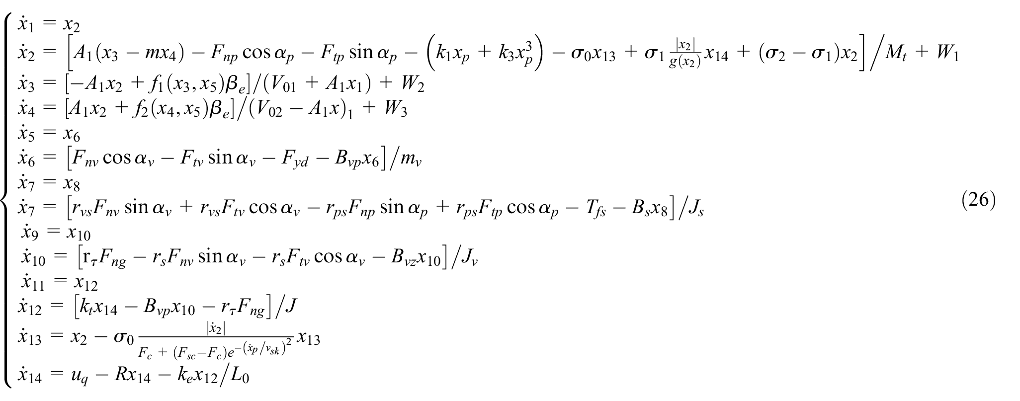
State space model of digital hydraulic cylinder
The system control input is
In the formula:

Regarding hydraulic cylinder load force and leakage as system disturbance, namely:
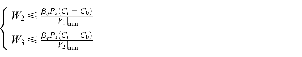
Therefore,
Neural network model reference adaptive disturbance rejection controller design
In this paper, a digital hydraulic cylinder MRAC (Model Reference Adaptive Controller) closed-loop system is designed as shown in Figure 7. The error is formed by the observation state and the state output of the reference model, and the adaptive control law is designed through the state variables of the object to form an adaptive system. Due to the inaccurate state estimation of the observer, there is an observation error. The RBF network is used to approximate the unknown function FZ, which increases the robustness of the system and the self-tuning ability of the controller parameters. 30

The structure of robust adaptive disturbance rejection control system.
The digital hydraulic cylinder is a single input and single output system, and the state variables are completely observable. The state space model is:

In the formula,
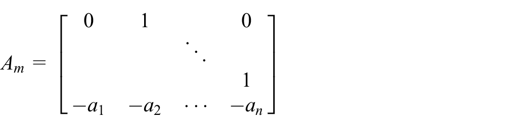
Given the system reference model state space equation is:
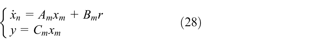
Where,
is stable and
Matrix


ESO is constructed for the controlled object in this paper, so that the system state can be observed:

In the formula:


Set the control to:

In the formula

RBF network is used to approximate the unknown function

Which
Therefore, the controller is designed to:


The controller

Since ESO can observe the state of the system, there are

The state error equation (36) obtained by simultaneous Formulas (34) and (35) is:

The core of the system design scheme is to track the reference model through the state of the state observer, and to find the adaptive law of

When

Then the equation transforms to:

By eliminating

In the formula:
Constructing Lyapunov function of the system:

Where,

In the formula:
According to the stability analysis of active disturbance rejection control system, it can be concluded that the observation error of state extended observer is bounded, then it can be deduced:

Since

Without considering the observation error, in order to ensure

Therefore

To simplify the system equation, let:
According to the definition:
So the Lyapunov function of the system is expressed as:
According to the above theoretical analysis, the neural network model adaptive disturbance rejection control strategy designed in this paper can ensure that the closed-loop system is asymptotically stable, and the displacement of the digital hydraulic cylinder can gradually track the output of the model reference.
Simulation analysis
In order to verify the effectiveness of the control method designed in this paper, a simulation model of digital hydraulic cylinder is built based on Matlab/Simulink platform. The simulation model is shown in Figure 8.

The simulation model.
The basic simulation parameters are shown in Table 1.
The structure parameters of digital hydraulic cylinder.

The desired position tracking command of the simulation system is a step signal, whose size is 0.06 m and to generate a step in 1 s. The parameters of the active disturbance rejection controller of the neural network model are:
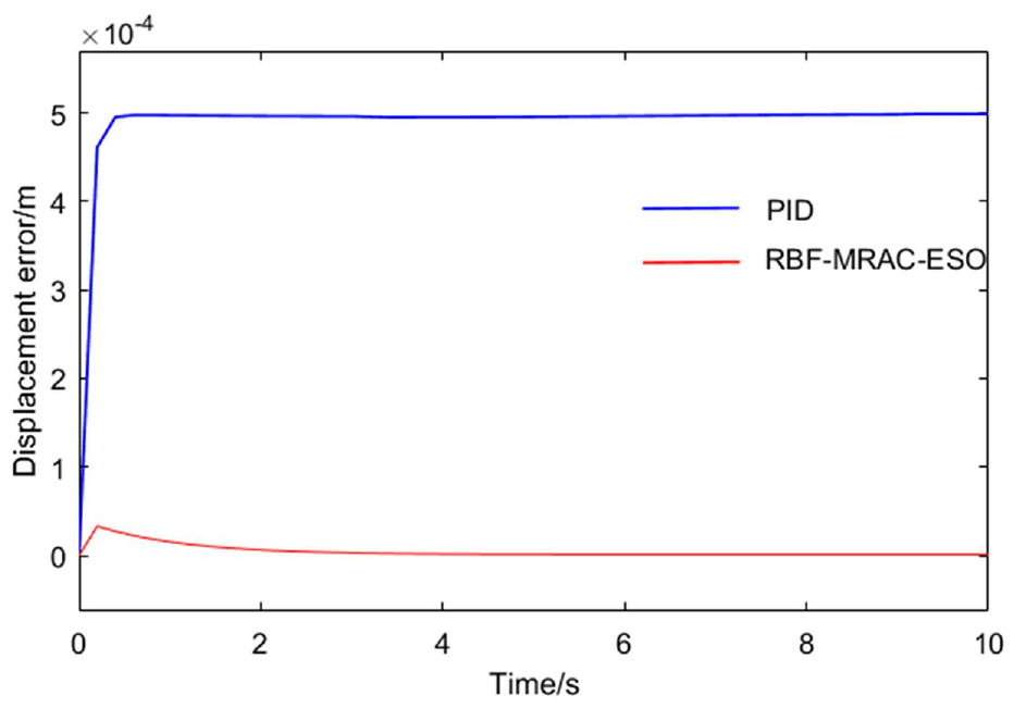
Figure 9 is the piston displacement tracking curve of the system, and Figure 10 is the tracking error curve. It can be seen from Figure 9 that the system under PID control cannot track the command signal well, its steady-state time of its step response is about 5.79 s, and from Figure 10, its steady-state error is 0.001058 m, and its steady state accuracy is
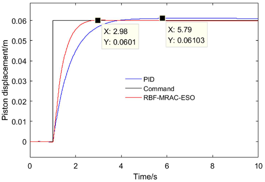
The curves of piston displacement.

The error curves of piston displacement.
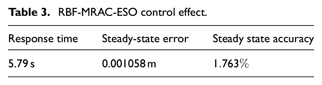
Tables 2 and 3 show the control effect of the system under RBF-MRAC-ESO and PID control respectively.
RBF-MRAC-ESO control effect.

RBF-MRAC-ESO control effect.
When the desired position tracking command is

external

The curves of piston displacement.

The error curves of piston displacement.
When the desired position tracking command is a custom signal, the parameters of the neural network model ADRC controller are consistent with those under the step instruction signal. PID control parameters are:

The curves of piston displacement.

The error curves of piston displacement.
When the desired position tracking command is a

The curves of piston displacement.
The error curves of piston displacement.
From the above simulation results, it can be seen that the neural network model ADRC controller designed in this paper has high control accuracy and performance. At the same time, when the parameters of the controller are determined, it does not need to modify the control parameters greatly because of the different command signals. The above two points are not solved by the traditional PID controller.
Conclusions
In this paper, the digital hydraulic cylinder is the studied object. In view of the problems of multiple clearance nonlinear links and nonlinear friction in the digital hydraulic cylinder, this paper proposes a neural network model adaptive disturbance rejection control strategy based on model reference adaptive, ESO and neural network. The results show that compared with the traditional PID control, the neural network model active disturbance rejection control can improve the stability, response speed and reduce the static error of the system. When the command signals are different, the traditional PID parameters need to be greatly modified, while the parameters of the ADRC controller of the neural network model hardly need be modified, which saves the workload. The control strategy effectively suppresses the adverse influence of nonlinear disturbances and nonlinear links on the system, can effectively improve the response characteristics of the system, reduce the steady-state error of the system, and has better adaptive ability and improves the robustness of the system.
Footnotes
Handling Editor: Chenhui Liang
Declaration of conflicting interests
The author(s) declared no potential conflicts of interest with respect to the research, authorship, and/or publication of this article.
Funding
The author(s) disclosed receipt of the following financial support for the research, authorship, and/or publication of this article: This work was supported by the National Natural Science Foundation of China under Grant 52204169.