
Abstract
Reducing the environmental impact necessitates a boost in renewable energy conversion systems. Wind energy is regarded as one of the most essential energy sources. For this purpose, the high wind variations in the energy conversion chain require robust and reliable control. This research aims to implement a regulation based on artificial intelligence toward a blade orientation mechanism to improve the stability of energy conversion. On the other hand, an energy maximization technique called Maximum Power Point Tracking (MPPT) is integrated into the control system. A developed program in MATLAB estimates the turbine performance with two different strategies, namely the MPPT technique and the Pitch control mechanism. For the best control and more stability of energy conversion, three artificial intelligence controllers, which are Neuronal Network (PI-ANN), Fuzzy Logic (PI-FLC), and Neuro-Fuzzy (PI-NFLC), were employed. They are compared with the conventional controller (PI-C). This comparison is made to distinguish the most robust regulator against wind speed variations. The different performance indices showed that the controller PI-NFLC has an excellent response, with an Integral Time Absolute Error (ITAE) of 375.28, whereas the Integral Absolute Error (IAE) and Integral Time Square Error (ITSE) equal 13.87 and 406.59, respectively.
Introduction
Energy is a major factor in socioeconomic development, durable development, and enhancing the human quality of life. In the future decades, the world’s population and economic activity will increase energy demand.1–4
In recent years, wind energy has grown rapidly and steadily. Over the next 30 years, wind energy will contribute to 18% of the worldwide electricity generated.5–7 Two consecutive records for the amount of new capacity created in a single year were broken in 2014 and 2015, with 52 and 63 GW installed, respectively. This brought the total capacity of the globe to over 433 GW.8–10 As environmental challenges have grown, renewable energy has grown in popularity. One of the most significant obstacles that wind energy must overcome in the present day is that of maximizing energy output from wind farms, which is dependent on the ideal power of each wind turbine located inside the park.11,12
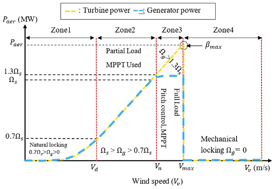
However, wind turbines (WTs) provide power that is exactly proportional to the cube of the wind speed.13,14 This results in a lot of variety, especially as the wind speed fluctuates constantly and arbitrarily. The turbines will not be able to produce constant power indefinitely. These variable-speed wind turbines use different strategies like the MPPT (Maximum Power Point Tracking) technique and the pitch control mechanism. The MPPT maximizes the power in the second and third operation zones of the system. Pitch control is dedicated to protecting wind turbines against strong winds by the orientation of the blades. Aerodynamic torque management is needed for wind turbine monitoring. Variable-speed variable-pitch technology is recommended for medium and large-scale wind farms to enhance generated energy and convert aerodynamic power efficiently and inexpensively.15–17 In order to do this, a device that can optimize the power taken from the wind at times when the turbines’ output is in different zones. 18 The variable mode of operation also helps mitigate the effects of the intermittent nature of wind power, which may put unnecessary strain on mechanical parts. Figure 2 illustrates the three primary zones in which the wind system runs, each with its own goals determined by the available wind speed. In the first zone, when the wind speed is insufficient for starting, control is exercised. This means that no power is being harvested since there is no torque. The goal of the regulation in the second zone is to maximize electricity harvesting. Here, while maintaining a fixed pitch angle, the rotating speed is varied to achieve a maximum power coefficient. As long as the wind speed does not exceed the rated value that corresponds to the rated generator speed, the system will continue to function in this partial load zone. When the wind speed in the third zone exceeds the rated quantity, the pitch angle control is used to keep the generator speed at the rated value by maintaining the rated power. The amount of energy that can be extracted decreases as the blade angle increases.
The scientific literature contains descriptions of projects that made use of the pitch angle control approach. Others use the turbine’s power maximization technique with different controllers, such as P. Venkaiah and Sarkar, who developed a fuzzy anticipation PID controller for pitch control of horizontal axis wind turbines using an electro-hydraulic pitch actuation system. 17 Civelek, used the genetic algorithm in this implementation to optimize a fuzzy logic controller (Takagi-Sugeno) with intelligent auto-tuning for the control of the stall angle of a wind turbine powered induction generator to make the output power even better. 19 Chen et al., implements a fuzzy hybrid control of the caged synchronous generator of a low-power wind turbine by controlling the stall angle using RNN. 20 Zhang et al. suggested an interesting tool for robust design optimization of airfoils with random aerodynamic factors. Their presented technique is straightforward and accurate, based on aerodynamic simulation. 21 Asgharnia et al., recommends using sophisticated controllers like FPID and FOFPID to improve pitch control performance. 9 Tauseef Aizedet al. examined how wind speed data can be collected, how a wind-driven water pumping system can be designed, and how the design can be analyzed under a variety of wind conditions in Pakistan. 22 Anil Naiket al. used Type 2 fuzzy logic proportional-integral controller to manage the turbine torque (WTs). 3 Yunfeng Li looked for a way to calculate the internal load distribution of a pair of single-row tapered roller bearings that double as support for the main shaft of a wind turbine using a 5-degrees-of-freedom mechanical model. The technique involved analyzing the main factors that affect how the internal load is distributed, such as axial preload, ring tilt, and roller crown. 23 An FDI system for a 4.8 MW wind turbine was developed by Ayoub EL Bakri and Boumhidi which was described using numerous Takagi-Sugeno (T-S) models. 24 When a PMSG is constructed in MATLAB, some study employs ANN-based pitch control for MPPT in wind turbines.
Table 1 summarizes the key contributions to the development of universal dynamic WTs. The key contributors to each work published are identified using this categorization. These studies are of great interest for manufacturers of wind turbines.
Summary of typical wind turbine model contributions.

The performed studies are not sufficient for the wind conversion chain in the technical literature. The best control and better protection of the wind turbine infrastructure is a significant challenge. Using control based on artificial intelligence with different strategies is highly recommended to solve these challenges. On the other hand, The regulation mechanism based on the conventional regulator is sensitive to wind variations, which causes loss of control and minimizes the reliability of the conversion system.30–32 In this study, Sun et al. improved the weaknesses of the conventional regulator in different research fields. The standard proportional integral (PI) speed loop was abandoned in favor of a sliding mode controller in the first research to boost steady-state performance. 33 In a second study, researchers compared the efficiency of the suggested technique to that of the conventional, low-speed sensorless approach using a battery of experiments using PMSG. The suggested low-speed sensorless system has been shown successful in experiments. 34 This article provides a sensorless approach for controlling permanent-magnet synchronous motors. The suggested technique has been experimentally tested and compared to the standard PLL under various settings. This novel approach maintained excellent steady-state performance and reduced speed, angular, and transient oscillations. 35
In the present work, a performance study based on artificial intelligence (PI-ANN, PI-FLC, PI-NFLC) monitoring is used. Results of the adaptive neuro-fuzzy controller (PI-NFLC) are compared with the results of the conventional controller, along with those of the neuronal networks and fuzzy logic controllers to improve the stability of the pitch angle mechanism and limit the output power at the rated value in the full load conditions. The main reason for this work was the lack of research on neuro-fuzzy control based on a mix of these two techniques, where tuning the three main parameters is the most important thing. There are scaling factors, membership functions, and rules tables that make out these parameters.
The hybridization of the neuro-fuzzy controller with the regular PI controller approach is then used to construct an adaptive law. Consequently, the scaling factors will be automatically modified based on the correction factor produced from the gain scheduling PI approach. This increases the flexibility of the controller to maintain high performance and to deal optimally with the highly nonlinear behavior of the turbine on one hand and the load disturbances caused by wind speed variations on the other hand. The proposed adaptive neuro-fuzzy controller’s transient performances are compared to those of the classical PI controller (PI-C), neuronal network PI controller (PI-ANN), and fuzzy logic controller (PI-NFLC) using four performance indices: Integral Absolute Error (IAE), Integral Time Absolute Error (ITAE), Integral Square Error (ISE), and Integral Time Square Error (ITSE). The electrical power smoothing capability of the aforementioned controllers is also evaluated, as is the steady state performance by using the standard deviation and Total Harmonic Distortion (THD) as performance indicators.
The article is broken down into five sections. The methodology is described in the first section. The wind turbine (WTs) model is briefly described in the next section. A simpler mathematical model is derived in the third section. The fourth section summarizes the different types of controllers used with pre-existing proportional integral controllers with the control techniques. Finally, a section presents the comparison performance results of the types of controllers (PI-C, PI-ANN, PI-FLC, PI-NFLC) applied to a high-power WT.
Methodology
In the face of severe disturbances, the performance of fixed-gain controllers (PI) does not accurately forecast the system’s response, short circuits and wind speed variations, for example. For a certain operating point, the PI controller’s fixed gain provides excellent steady-state performance. Even though the operating point of the converter changes all the time because of how the plant works, it is not unusual for it to have bad transient performance. Figure 1 represents the proposed artificial intelligence controller integrated in wind turbine conversion chain for predicting performance.
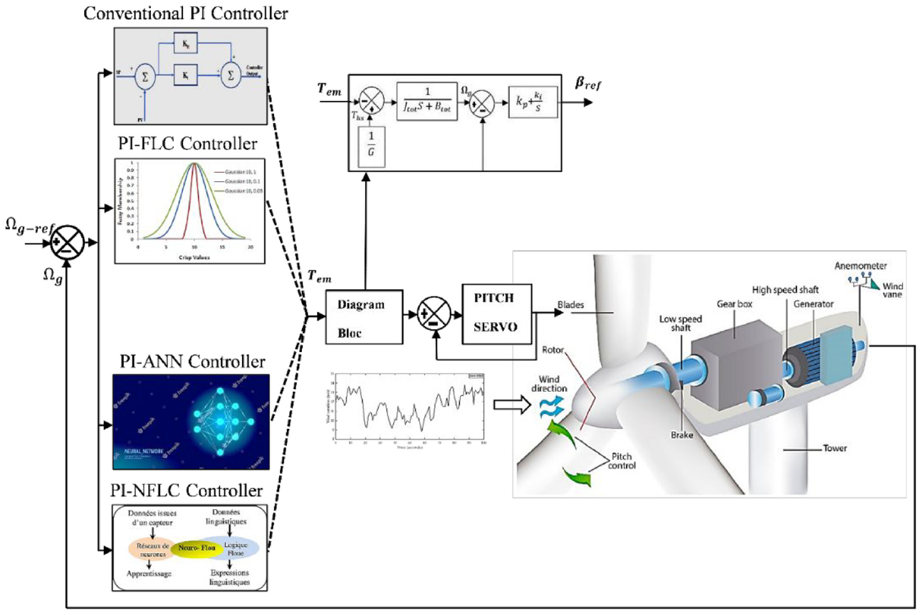
Bloc diagram of suggested pitch control using regulators.
The five-step workflow is described as follows:
The relative wind data is simulated based on a Nikita’s model at the predicted capacities of the high-power wind turbines, which are collected in a first step.
The turbine’s modeling contains two masses, and the second phase involves using a simulation tool to depict the energy performance.
Integration of control technique for extracting the maximum power and pitch control mechanism for the third operation zone based on a linear PI controller is planned in the third step.
The synthesis of artificial neuronal network, fuzzy logic and neuro-fuzzy logic regulators is based on software simulation. For good performance, control in transient systems with severe wind disturbances is projected in the fourth step.
The fifth step is to examine the wind turbine’s performance parameters, such as electromagnetic torque, generator speed, turbine speed and torque, power coefficient, relative wind speed, and pitch angle.
System description
Two control systems are combined in a high-power three-bladed WT. This system has a pitch control, a mechanism to control how the blades turn, and mechanical power. The MPP approach is used in order to get the most possible power from the wind. The doubly fed induction generator, often known as the DFIG, offers more flexibility in terms of connecting to the electrical grid.30,31 The four zones in which a variable speed wind turbine operates are as follows:
Zone 1: The wind speed is lower than starting inertia turbine condition that mean the importance of the turbine’s inertia, resulting in no power being provided.
Zone 2: The wind turbine operates in partial load mode, when the wind speed variation exceeded (Vd) until nominal speed (Vn). The pitch control mechanism is operated under fixed angle β = 2° in this zone. The power range between the synchronous speed (Ωs) and (0.7Ωs) below the synchronous speed. In this zone, the wind speed creates kinetic energy that drives the turbines. The turbine can sustain power levels that are typically greater than the power levels necessary to run the generator. This zone incorporates algorithms to maximize the power transferred using MPPT.
Zone 3: Figure 2 shows how the wind turbine works when the MPPT method with pitch control is used. The speed of the generator (Ωg) controlled when the wind speed (WS) is between the nominal value (Vn) and the maximum value (Vmax). The speed generator exceeds (1.3Ωs) above the nominal speed, this decreases the blade angle and creates a variation in the power coefficient (Cp). Therefore, it requires regulation of the turbine speed to provide a supportable power level.
Zone 4: The wind turbine is operating under mechanical locking caused by the high-speed generator. On the other hand, the blade angle exceeds the saturation states β = β max .
Wind turbine aerodynamic power generated.
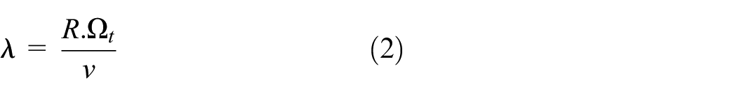
As long as a particular speed (λ) greater than the cut speed is achieved, wind energy may be harvested to the greatest extent feasible even when the wind speed falls below the rated wind speed. The MPPT control is another name for this frequently used control method. According to this analysis, in order to keep the output of the wind turbine at the nominal value while reducing mechanical torsion and extending the wind turbine’s life cycle, we must keep the wind turbine at the nominal value by controlling the pitch angle mechanism of the step power coefficient to a suitable value to maintain output power stability. 36
On the basis of the preceding assessment, Figure 2 shows that the working zone of the wind turbine (WT), in zone 2, is a step of MPPT, generator velocity, and power growth as wind velocity increases. Zone 3 is a period of continuous operation where the change in pitch must be controlled to keep the generator’s output power and speed at their nominal values. 37
Modeling system
Figure 3 depicts a conventional variable-speed wind turbine, which includes an aerodynamic system, a gearbox, and a generator. Everything that contributes to mechanical torque being transmitted to the axis of rotation is put together as a powertrain or mechanical transmission system. Mechanics modeling can range from simple to complex, with some models employing as many as six masses depending on the complexity of the system being modeled.37,38
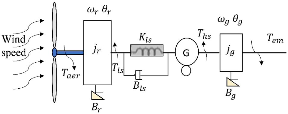
Wind turbine dynamics.
The model’s inputs will be aerodynamic and electromagnetic torque, while the output will be rotation speed. The model’s simplifying assumptions are as follows:
The blades’ flexible modes are thought to be high enough to be ignored, while the flexible modes are found in the slow shaft’s flexible element. The fast shaft, on the other hand, is regarded as indefinitely stiff.
The inertia of the gearbox and the slow shaft is integrated with that of the rotor (Jr), which represents the whole.
The inertia of the hub can be ignored because it accounts for only 1% of the total inertia of the turbine. The inertia of the fast shaft connected to the generator is represented by (Jg).
The torsion of the turbine axis, in terms of stiffness constancy, can be calculated analytically, provided that its geometric shape is known.
The torsional forces of the blades, hub, multiplier, and slow shaft are all included in the total elasticity coefficient (Kls) of the slow shaft.
Viscous friction on the bearings of the drive unit is taken into account by the coefficients (Kr) and (Kg).
The inertia of the turbine is substantially equal to that of the blades.
The aero turbine, gearbox, and generator are all illustrated in Figure 3 of a variable-speed wind turbine. For the rotor’s aerodynamic power capture, the non-linear expression is 38 :

The power coefficient (Cp), which is the linear blade tip speed, is proportional to the wind speed (v). The blade pitch angle (β) and the tip-speed ratio (λ) both have an impact on the power coefficient. 39
Due to the tip-speed ratio being affected by the wind speed or rotor speed, the power coefficient shifts. This affects the amount of electricity produced. According to the following equation, the power coefficient is proportional to the aerodynamic torque coefficient, profiting from a partnership.

The following equation is used to determine the aerodynamic torque expression:

The power coefficient (Cp) for a 2 MW wind turbine can be calculated using the equation below.40,41

C1 = 0.5, C2 = 116, C3 = 0.4, C4 = 0, C5 = 5, C6= 21, and x = 0
The dynamic response of the rotor driven at a speed (Ωr) by the aerodynamic torque (Taer) is shown

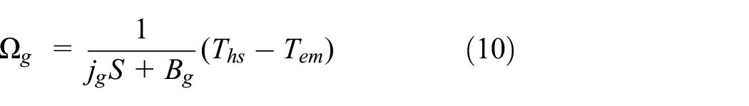
The high-speed shaft torque (Ths) drives the generator, while the generator electromagnetic torque brakes it (Tem).

The rotor is slowed down by the low-speed shaft torque (Tls). Because of the discrepancy between (Ωt) and (Ωls) which occurs from torsion and friction effects.

By applying the Laplace transformation, we obtain:

Using an ideal gearbox and transmission ratio, the following equations may be derived (G).

It is possible to represent the turbine as a single mass by using equations (8) and (11) with a completely stiff low-speed shaft:

with

The total inertia, friction coefficient, and torque of the generator returned to the slow shaft are represented by the parameters (Jtot), (Btot), and (Ttot). The generator’s inertia is frequently disregarded in favor of the rotor. The last equations allow the block diagram of the turbine model Figure 4 to be created.
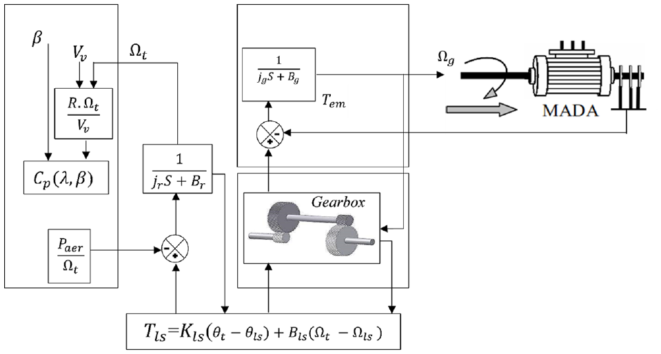
The aerodynamic model’s block diagram.
Electrical performance of wind turbine generator controllers
Two different techniques are used in this study. The turbine has developed its approach to pitch control mechanism and its MPPT technique. Figure 5 illustrates the use of many controllers to evaluate their contribution to the wind energy conversion system (WECS).42,43
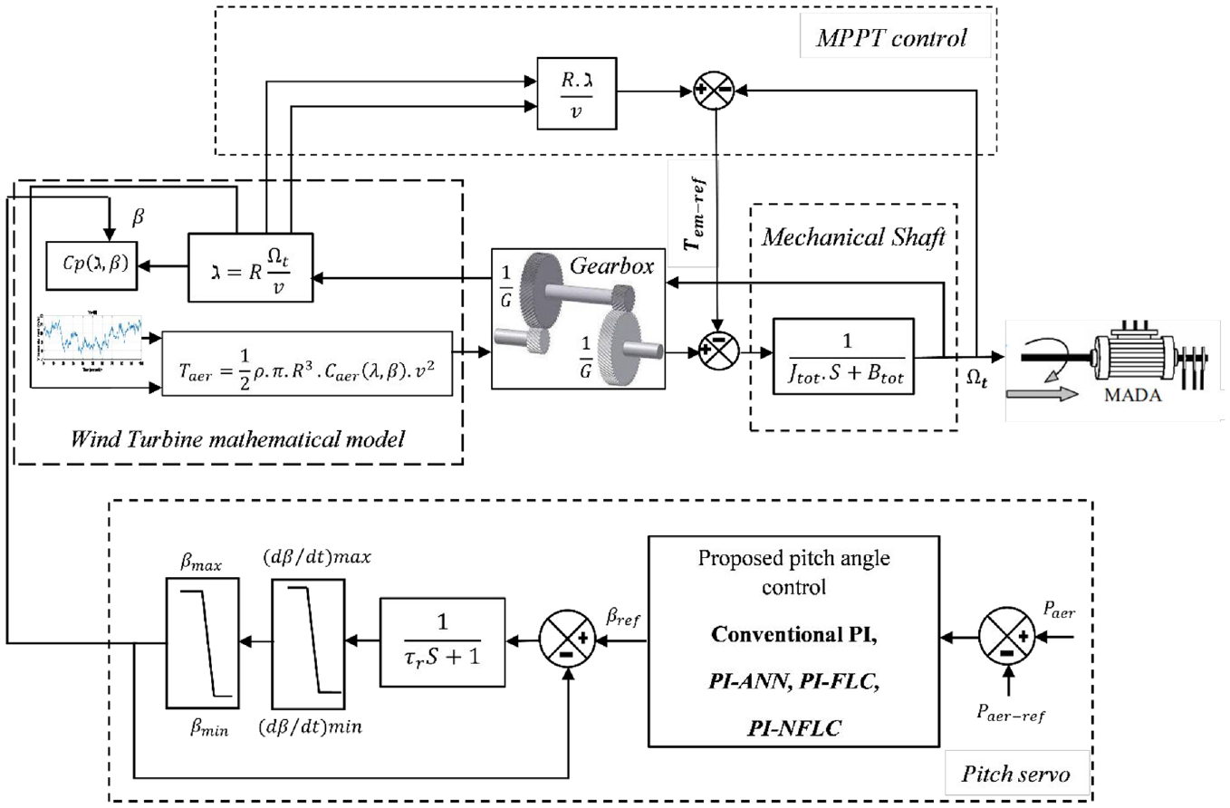
Diagram of a variable pitch control based DFIG.
Controller strategies
MPPT control
In below-rated circumstances, the goal is to capture as much wind power as possible. Figure 2 shows that for each wind speed, the turbine gets more speed until the speed limit supported by the turbine is reached, which means that the turbine gets maximum power at a certain rotor speed, and power follows a cubic regression in terms of rotor speed.44,45
In order to obtain better results, the system will need to make use of the MPPT approach while operating at variable wind speeds. In this particular investigation, a control strategy known as Tip Speed Ratio control, which is based on the PI controller, is used. When the TSR is set to its best value and the wind speed is measured at that point, the rotor’s best speed, which can be written as 46 :

The regulator uses quick dynamic speed adjustment in order to create an electromagnetic torque with a steady state reference value of the rotor’s steady speed 31 :

The functional diagram for the direct torque approach may be seen in Figure 6. The DFIG has two cascading control loops, as can be shown. Iqr is controlled by the vectorial command, which was discussed before. It is thus possible to relate the speed of the control loop rotor to the torque produced by this component. It is determined by comparing the recorded wind speed with the TSR value.

Diagrammatic representation of the MPPT method.
There is more dynamic activity within than outside of the inner loop, thus PI gains are calculated using the pole cancelation approach and a crossover frequency in open mode that is an order of magnitude lower than the internal loop’s crossover frequency.
Pitch control
A controller and an actuator compose the variable pitch system. Servo control of the blade’s rotation is provided by the actuator, which is a nonlinear system. The height controller’s output signal can be thought of as a dynamic system with an amplitude and a saturation point. 47
The aim is to allow the rotor to get the most wind at all times. The blades can have a different pitch angle adapted to the wind that faces them. The explanation diagram for pitch angle regulation in wind energy conversion systems can be seen in Figure 7, which can be found here. 48

Operating diagram of a wind turbine generator.
In Zone 02, the blade angle is fixed, the rotor speed is in a steady state, and the specific speed is at its optimal value. To prevent damaging the structure in Zone 03, it is important to control the blade angle. This variation starts from a maximum speed supported by the generator with a value higher than 30% of the synchronization speed. The variation of the blade angle controls the aerodynamic torque. It is constant, and the wind turbine produces its power.
This section is going to concentrate on the control system, and Figure 8 is going to depict the actuator of the pitch control.
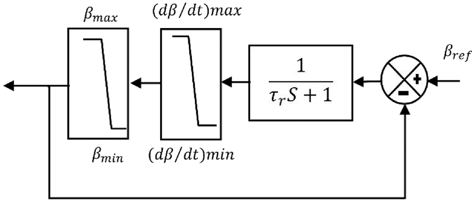
Diagram of variable pitch actuator.
The following is a description of its dynamic behavior 44 :

where β, βref are respectively the actual and given pitch angles, τr is the actuator time constant. Normally, beta ε(0°; 90°), The rate of change of pitch angle is within −10°/s; +10°/s.
Figure 9 depicts the pitch control strategy’s block diagram.

Schematic representation of the pitch-controlling approach.
The electromagnetic torque is maintained at its rated value in order to ensure that the correct amount of electrical power is being regulated. As a result of the blades being controlled by a hydraulic electric actuator, the pitch angle is confined and limited to falling within the range of 2° to 90°, which is illustrated by the saturation block in the same figure. 40
Controller design
Proportional-integral controller
Because of its straightforward design, the PI controller is the type of controller that finds the most use in industrial settings. It causes the angle of the blades to change based on how fast the rotor is moving, which is an error in pitch control.31,47
In the Laplace domain, the conventional PI control is defined as 33 :

Equation (20) may also be stated in the s-domain to provide the result shown below:

The closed-loop transfer function T(s) is found by substituting equation (20) with equation (21):

The stability condition is the first factor to consider while choosing PI gains. 49 For a stable closed-loop system, the denominator roots should be negative or the polynomial coefficients should be positive: (-A-BKp > 0) and (-BKi > 0).
Finding the right controller gains is done by comparing the denominator to the standard form, which is written as:

Where
Thus, Ki and Kp are given by:
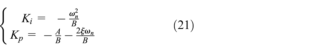
There is a link between B and the angle of the blades and the partial derivative of the turbine torque. the angle of the torque curve changes considerably from one equilibrium point to the next. Because of this, choosing this equilibrium point as the operating point is a challenging task that must be performed in order to get good results. 49
Fuzzy logic controller (FLC)
Non-negative linearity is mitigated via fuzzy logic, which increases performance. Unknown parameters, input parameter variations, and external perturbations are among issues that traditional controllers must face. Gains are planned using FLC. In terms of dynamic input parameters and external disturbances, conventional controllers outperform appropriately developed FLCs. 32 This is due to the fact that it does not rely on a mathematical model to utilize. Variations in aerodynamic torque susceptibility are compensated for by the blade pitch control gain regulation.
The fuzzy controller manages the two parameters proportional and integrator gains (Kp, Ki) as indicated in Figure 10. 47
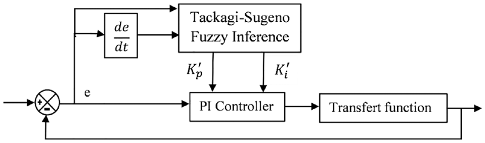
Schematic representation of the T-S fuzzy PID topology.
After fuzzy reasoning and function clarification, they input the adjustments of the two parameters K′ p and K′ i into the PI controller, setting them in real-time using the following equation 50 :

In general, the FLC consists of two steps
Fuzzification
The fuzzy field of the input variables error (e) and error variation (de) is defined as [−1;1], according to our standards. Negative big, negative small, around zero, positive small, and positive big are the seven language value variables that are used for input and output, respectively. These language value variables are abbreviated as “NB, NS, AZ, PS, PB.” The membership function that is shown in Figure 11 is a hybrid of the triangle function and the trapeze function.
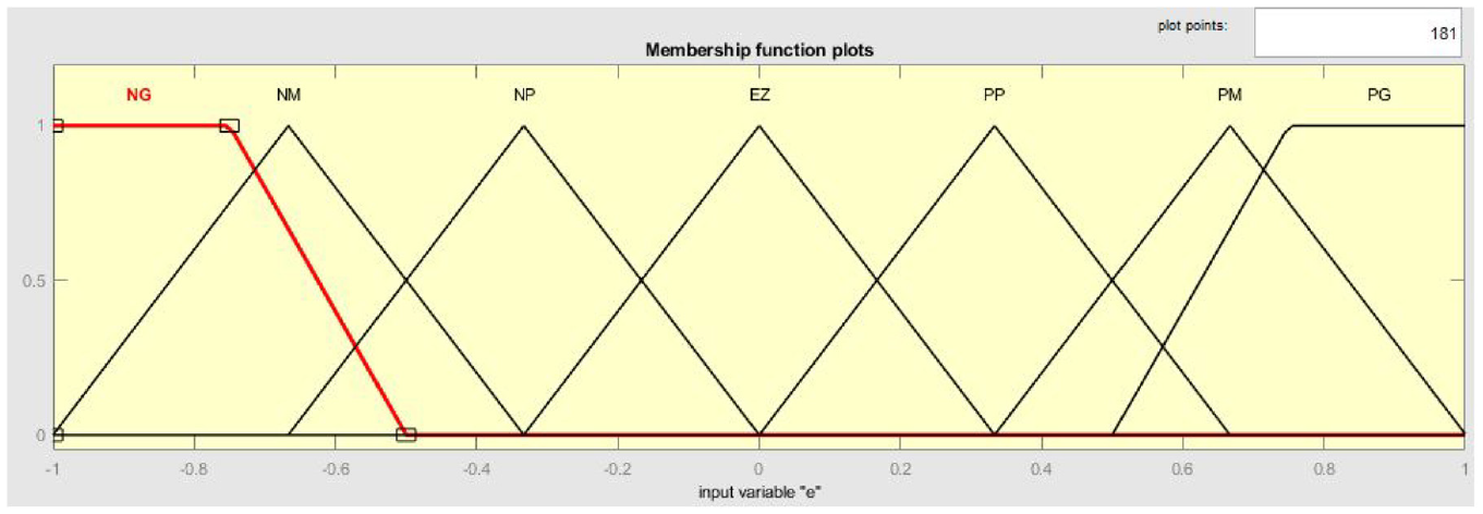
Membership function.
The 3D image simulation of two inputs (e, de) and output variation control (du) is given in Figure 12.
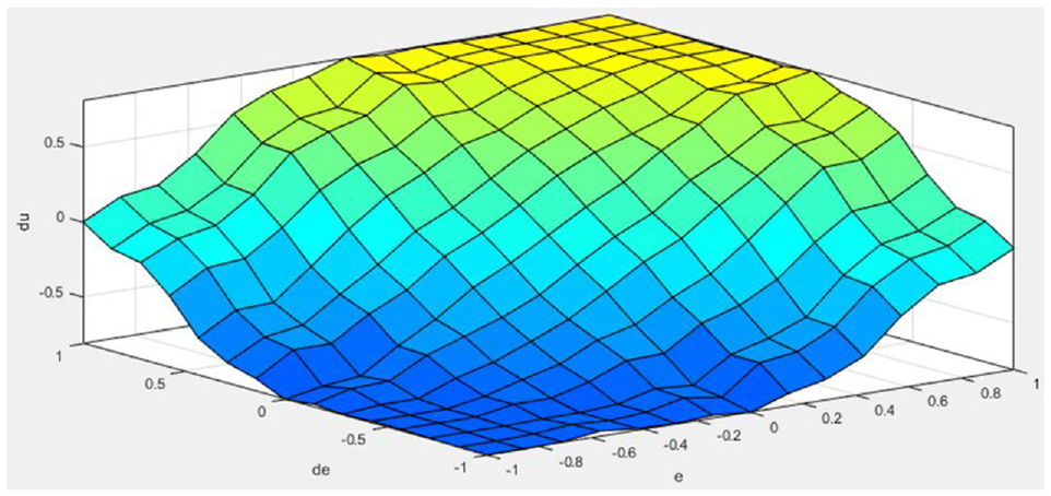
3D image of e, de, and du simulation outputs.
The fuzzy control rules of PI controller’s two parameters Kp and Ki are shown in Table 2.
Fuzzy rules
Fuzzy logic control rules.

with: e: Mistake (ε), de: Error derivative, du: Control derivative
The establishment of a database and the formulation of fuzzy controller action rules are both required at this stage of the process. As opposed to formal predicate compute statements, it may be explained using words or straightforward phrases spoken in a language that is commonly used. The rules are organized in an IF-THEN pattern. 38
Mamdani Inference Model: IF: e = NB and Δe = AZ then Δβ = NS Takagi-Sugeno-Kang: IF: e = NB and Δe = AZ then Δβ = f (NB, AZ)
A fuzzy set is transformed into a precise action with a real value. To satisfy mathematical expressions, the center of gravity method is used. We used Mamdani’s “MAX-MIN” method for numerical processing of inferences related to the RLF5 fuzzy controller, such as:
The operator AND: establishing a minimum
The operator OR: maximum training
Involvement THEN: training of the minimum
Aggregation: formation of the maximum
The output power error (e) and error variation (de) are used as input variables in this study, and the system is fuzzified to transform the accurate input quantity into a fuzzy quantity, which is expressed by the appropriate fuzzy set. The power fluctuation range of wind turbines should be kept to less than 10%. The error range is defined as −0.2 MW; 0.2 MW, and the associated error rate is set as −0.4 MW/s; 0.4 MW/s, because the rated power of the direct-drive wind generator analyzed in this work is 2 MW. The fuzzy area of error (e) and error variation (de) could be regarded as {−1; 1}, and the scaling factor of error and error time variation can be calculated as follows 50 :

The corresponding model of a two-input, one-output fuzzy PI controller is created as illustrated in Figure 13 based on the previous model.

T-S fuzzy PI model of variable pitch system control.
Artificial Neural Network Controller (ANN)
A Multi-layer perceptron-type (MLP) non-recurrent network model is chosen for identification and control. 41
The Figure 14 shows the principle of direct identification of a conventional controller. 43

Schematic of a system for pitch control with a direct identification PI controller.
Different techniques can be used with one or more hidden layers, in which each neuron in one layer is connected to those in the next layer. The neurons in the various hidden levels have sigmoid, tangential, or logarithmic activation functions. At the same time, those of the output layer are linear. 51
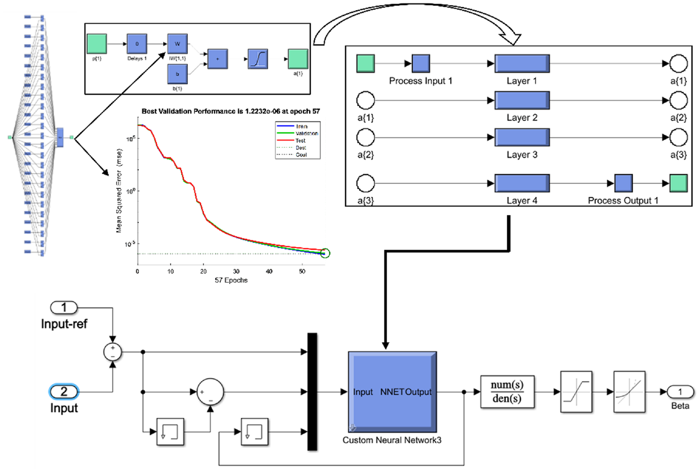
Due to the internal feedback loop, the RNN is robust to various environmental conditions and wind torque perturbations, allowing it to perform nonlinear dynamic mapping. Furthermore, the RNN outperforms other frequently used NNs in terms of speed and efficiency, making it ideal for real-time control and identification applications. 43 As illustrated in Figure 15, The RNN the type multi-Layer-perceptron (MLP) has two inputs in the input layer, 25 neurons in the first hidden layer, 10 neurons in the second hidden layer with “logsig” function in both layers. One output neuron in the output layer with “pureline” function, is employed to approximate the dynamics of the generator.

RNN topology.
The activation function is a LogSig:

Neuron output identification:

Update of synaptic weights:

Bias update:

By increasing the number of interconnecting weights and neurons in the hidden layer, the RNN approximation’s accuracy may be greatly improved. By choosing proper connection weights and a reasonably high number of neurons in the hidden layer, the approximation error may be greatly decreased to arbitrarily small over a compact set. 20
The appropriate model of two input and one-output Neuron PI controller is created according to the aforementioned configuration, as illustrated in Figure 16.
Variable pitch mechanism is controlled using a PI-ANN model.
Neuro-fuzzy controller
As shown in Figure 11, the “if-then” rules below define a fuzzy controller (FLC), which can be easily implemented as a neural network. The speed error and speed error derivative input nodes on the controller are used, with one presenting the control. The input node feeds the intermediate layer, also known as the hidden rules layer, through weighted connections.5,10
The definitions of these weights are linguistic variables or fuzzy sets. Using these shared weights, the input error is translated into linguistic variables and delivered to the rule layers. Each rule layer responds to the data in a parallel manner. The input layer’s input (error and error derivative) conditioned by the fuzzy weights is used by the ruling layer to identify the inputs’ conjunction (fuzzification). 19
The rule layer’s output is transmitted through weighted connections to the output layer (control layer). The weights are output fuzzy set definitions, and a defuzzification technique is applied at the end. It is referred to as the “modified center of gravity” strategy. The synthesized NFC regulator is shown in Figure 17.

PI-NFLC control model of variable pitch system.
The 3D image simulation of two inputs (e, de) and output variation control (du) is given in Figure 18. 42

3D image of e, de, and du simulation outputs.
Results and discussion
The proposed artificial intelligence controller is put to use on a wind system that has been modeled in Matlab/Simulink. This is done to show how well it can control mechanical speed and keep wind disturbances from happening. To model the WT, the characteristics of a three-blade WT model are used. Table 3 includes a list of these parameters. 48
Simulation parameters.

In general, each manufacturer’s brochure provides extremely minimal information. The characteristic curves and certain rating parameters are generally the constrained data collected from manufacturer documentations. The goal is to explain some important rules that can be used to get the parameters needed for modeling from curves.37,48
For 100 s of simulation time, the four aforementioned controller responses were evaluated in terms of robustness and precision, utilizing a variable WS and turbulent WS profile. The wind speed that was selected by using Nichita’s model, as shown in Figure 19, has a value of 11 m/s on average, with minimum and maximum values of 9 and 13.5 m/s, respectively. This was done to make sure that the wind speed chosen stayed higher than the rated wind speed for the whole simulation. 29

Wind variation profile.
As the wind speed increases from 12 to 13.5 m/s, the generator speed reacts to the initial scaling variables as shown in Figure 22. The neuro fuzzy (PI-NFLC) regulator curve provides better dynamic characteristics, as seen in this figure. The rise time was increased from 4.5 to 1 s around the conventional regulator, and the overshoot was minimized.
On the other hand, the neuronal network and fuzzy logic regulators (PI-ANN), (PI-FLC) successfully provided a satisfactory response.
Integral Time Absolute Error (ITAE), Integral Absolute Error (IAE), Integral Time Square Error (ITSE), and Integral Square Error (ISE) are the four performance indices used in the study. The wind variation change from 11 m/s to 13.5 m/s characterizes the equilibrium point. Figure 20 illustrates the generator speed responses, while Table 4 lists the performance index values for each controller

Generator speed response under different regulators.
Under wind speed fluctuation, a comparison of generator speed responses based on four performance indices.

PI = proportional-Integral, PI-ANN = Artificial Neuronal Network regulator, PI-FLC = Fuzzy Logic Control, PI-NFLC = Neuron Fuzzy Logic Control.
It has been shown that the suggested method, the PI-NFLC, generates the desired performance, whereas the traditional controller generates the weakest results (PI-C). It is essential to keep in mind that the ideal controller is referred to as the one that reduces the values of those indices.
The FLC might be regarded as the second-best option if IAE, ITAE, and ISE are taken into consideration. On the other hand, the ITSE index recommends the neural network controller (PI-ANN) as a good control solution. This indicates that the PI-ANN controller is more effective than the PI-FLC controller in the section of the transient process that is near to the steady state. This problem is made very clear by the fact that the FLC method results in an undershoot while the ANN method does not.
For the purpose of providing more evidence about the efficacy of the proposed controller, the model of the wind system is sustained in the simulation by a changing wind intake coupled with a turbulence level of 2%. Figure 19 depicts the wind profile as a whole. In this particular evaluation, the performance indicators that are being used are the standard deviation (STD) and the total harmonic distortion (THD).
The adaptive neuro fuzzy logic (PI-NFLC) can tolerate significant wind disturbances and produce good rotor speed regulation around its nominal value, as shown in Figures 21 and 22. The conventional controller, on the other hand, produces substantial generator speed variations that can exceed 250 rad/s, or 17% of the rated value. The rotor overcurrent may cause damage to the power electronic converters. A satisfactory result can also be obtained with a fuzzy controller.

Generator speed responses.

Turbine speed responses.
Figure 23 shows the necessary pitch angles for speed control. It is evident that when the wind speed is strong, the pitch angle increases to reduce the amount of wind power captured. The suggested controller provides for greater pitch action at a faster rate than the previous controllers. This explains the rated speed tracking’s high dynamic performance. The pitch activity of the neuron network controller (PI-ANN) and fuzzy logic regulator (PI-FLC) is still acceptable, and the pitch angle actuator is requested at a lower level than the neuron fuzzy controller (PI-NFLC).

Pitch control profile under wind speed variation.
The power coefficient and relative speed curves are shown in Figures 24 and 25 respectively. As expected, the fluctuations in Cp were inversely linked to those of the pitch angle. This was because raising the blade angle decreased the power factor, which was done to restrict the amount of energy transferred.

Power coefficients variations.

Relative Speed variations.
The STD and THD are utilized as performance indices to compare the controllers under investigation in order to evaluate mechanical vibrations and power quality.
The aerodynamic torque oscillations are depicted in Figure 26, and the performance indices are summarized in Table 5. Neuron fuzzy control (PI-NFLC) provides the best results, since it has less oscillations and dispersion of variability around the average than other controllers. As a result, the suggested controller can reduce the mechanical stresses imposed on the turbine and gearbox.

Aerodynamics torque responses.
Under variable wind speeds, aerodynamic torque responses for different controller systems are analyzed.

THD = Total harmonic distortion, STD (σ) = Standard deviation.
As shown in Figure 27 and Table 6, the turbine mechanical power regulation performance is quite satisfactory when utilizing adaptive neuron fuzzy control. Under full load, the controller can keep the power generated at a level close to the nominal value, and the quality of the power has been greatly improved, with the lowest THD and STD. When compared to the traditional PI controller, the suggested technique achieves a significant gain of 19.62%, and 8.42% when compared to the second-best solution based on fuzzy logic controller. The THD index may be significantly reduced with the proposed controller.

Total turbine power transferred into grid.
Under variable wind speed conditions, performance analysis of turbine power responses for various controller designs.

THD = Total harmonic distortion, STD (σ) = Standard deviation.
Conclusion
This paper deals with the design of a pitch angle controller based on an adaptive artificial intelligence control, aiming at enhancing the power quality and reducing the mechanical loads when the wind system operates at the above rated wind speeds. The necessary results are summarized as follows:
- Firstly, four of the aforementioned controller responses (PI-C, PI-ANN, PI-FLC, PI-NFLC) were evaluated in terms of robustness and precision, utilizing a variable wind speed and turbulent wind speed profile. This last was selected using Nichita’s model, and has a value of 11 m/s on average, with minimum and maximum values of 9 and 13.5 m/s, respectively.
- The Integral Absolute Error (IAE), Integral Time Absolute Error (ITAE), Integral Square Error (ISE) and Integral Time Square Error (ITSE) are the four performance indices used in the study to judge the principal parameters that are analyzed of the WTs under wind speed fluctuations, as well as generator rotor speed and aerodynamic torque. On the other hand, the STD and THD are utilized as performance indices to compare the controllers under investigation in order to evaluate mechanical vibrations and power quality for the turbine power transferred to the grid.
- The wind variation changes from 11 to 13.5 m/s and characterizes the equilibrium point. In Table 4, it has been shown that the suggested method for the generator rotor speed and the neuro fuzzy (PI-NFLC) regulator curve provides better dynamic characteristics. The rise time was increased from 4.5 to 1 s around the conventional regulator (PI-C), and the overshoot was minimized. On the other hand, the neuronal network and fuzzy logic regulators (PI-ANN), (PI-FLC) successfully yielded a satisfactory response, whereas the traditional controller generated the weakest results (PI).
- The pitch activity of the neuron network controller (PI-ANN) and fuzzy logic regulator (PI-FLC) is still acceptable, and the pitch angle actuator is requested at a lower level than the neuron fuzzy controller (PI-NFLC).
- The aerodynamic torque oscillations are analyzed by the performance indices, which are summarized in Table 5. Neuron fuzzy control (PI-NFLC) provides the best results since it has fewer oscillations and dispersion of variability around the average than other controllers. As a result, the suggested controller can reduce the mechanical stresses imposed on the turbine and gearbox.
- As shown in Table 6, the turbine mechanical power regulation performance is quite satisfactory when utilizing adaptive neuron fuzzy control. Under full load, the controller can keep the power generated at a level close to the nominal value, and the quality of the power has been greatly improved, with the lowest THD and STD. When compared to the traditional PI controller, the suggested technique achieves a significant gain of 19.62%, and 8.42% when compared to the second-best solution based on the fuzzy logic controller. The THD index may be significantly reduced with the proposed controller.
- The results indicate that the proposed controller (PI-NFLC) can both achieve an accurate regulation of the generator speed and electrical power and give the best mitigation of the mechanical load effects compared with the other controllers. The tests reveal that fuzzy logic and neuronal network controllers give almost the same results and can be adopted as the second choice.
It is critical to use the neuron fuzzy to save the electrical device and extract the maximum power with quality transfer, which is demonstrated with STD (σ) and FFT analysis.
Footnotes
Appendix
Handling Editor: Chenhui Liang
Declaration of conflicting interests
The author(s) declared no potential conflicts of interest with respect to the research, authorship, and/or publication of this article.
Funding
The author(s) received no financial support for the research, authorship, and/or publication of this article.