
Abstract
In this literature, a new automated control strategy has been developed to manage the power supply from the wind power generation system to the load. The main objective of this research work is to develop a fuzzy logic–based pitch angle control and to develop a static transfer switch to make power balance between the wind power generation system and the loads. The power management control system is a progression of logic expressions, designed based on generating power and load power requirement. The outcome of this work targets at an improved power production, active and reactive power compensation and ensures system load constraints. To validate the proposed control strategy, a detailed simulation study is carried out on a 9-MW wind farm simulation simulated in MATLAB/Simulink environment.
Keywords
Introduction
Electrical power plays a vital role in day-to-day life of human society in all aspects. The renewable energy resources (RERs) play a major role in electrical power production, and it is estimated that the world electricity production through RER will be 45% by 2020. 1 Among various RERs, wind power generation system (WPGS) has become the most popular power resource in the past decade for its clean and low maintenance factors. 2 The use of WPGS for energy production undergoes a serious problem in providing the ancillary services. 3 The ancillary services include starting capabilities, voltage and frequency regulation, load power management, real and reactive power control. Considering a wind farm in a compact urban area network with several minor WPGS of 1 MW scale or more which are linked directly to the power network. It has been observed that the high fluctuating wind speed affects the power generation capacity of the WPGS. Furthermore, on one hand, as WPGS is grid-connected, it tends to affect the loads connected to the grid network. 4 On the other hand, the WPGS is not deployed to sense the change in loads in the grid network. 5 However, it is mandatory to develop an ancillary power management system to handle the load requirement based on the energy generation of the WPGS.
In recent years, meticulous research work has been carried out to improve the power production of WPGS during high fluctuating wind speed conditions. In the study of Ma et al., 6 synchronization of numerous wind turbines (WTs) has the tendency to counterbalance the power production and load demand. While performing synchronization, the generated power is sufficient to meet the demands. But the power generation is constant and they supply almost same amount of power even with low sensitive loads. 7 In another approach, Muyeen et al. 8 and Sitharthan and Geethanjali 9 have discussed that the load demand can be met by adding energy storage devices with the network. By adding so, the cost of the system increases and also requires additional control strategy to manage the energy storage devices. 10 An inverter-based controller has been implemented to monitor and control the load demand. 11 The inverter uses a control strategy to turn ON/OFF the load according to the requirement and power availability. Furthermore, an additional supervisor is required to control and monitor the power management controller and hence increasing the maintenance cost of the system. 12 Moreover, when the power production is very high, they do not balance effectively. Furthermore, pitch angle control system has been proposed to protect the turbine against mechanical failure from high wind gust and to maximize/minimize the power production according to the wind incident on the blades.13–17 A pitch angle controller adjusts the turbine blades inward or outward to extract wind power according to the flow of wind speed. The action of adjusting the turbine blades sequentially increases or decreases the power production. In the study of Minh et al., 18 a power management system has been developed and the power management communicates with innovatory pitch system to respond to changing load demands. 19 The power management is best employed with variable pitch control or stall control. Pitch control and stall control are employed in regulating the WPGS rotor and can increase the power production depending on the load requirement by adjusting the rotor speed. 20 A pitch angle control strategy is used to regulate the power through the pitch actuator, the only control system available in the WT, as there is no power electronic interface between the generator and the load to allow controlling the WT outputs. In recent times, the control strategy for the pitch actuator is achieved by various control techniques, such as conventional proportional–integral (PI) control method, fuzzy logic control method, hybrid control method, generalized predictive control method and neural network control method.21–29 These control methods make sure that the generated power output of the WPGS pursues the command value determined and offers steady output power. 21 In order to satisfy the energy constraints, a suitable control strategy must be provided to the WPGS. Consequently, the developed controller has to satisfy two objectives: (1) pitch angle control and (2) power management control to improve the overall performance of WPGS and grid network. As fuzzy logic controller (FLC) can handle problems with imprecise and incomplete data, it can model non-linear functions of arbitrary complexity. This model is preferred since it is cheaper to develop, covers a wider range of operating conditions and are more readily customizable in natural language terms. 18 Hence, as FLC has a higher advantage in dealing with the non-linear function, it is chosen as the control strategy to control the pitch actuator. This work mainly focuses on the power management of the wind farm composed of three variable speed WTs. The objective of the work is to fulfil the energy constraints of the load by managing the power production. In this work, a fuzzy logic control strategy–based pitch angle controller has been developed to control the pitch actuator. Furthermore, a Boolean logic–based static transfer switch has been developed to make power balance between the wind power generation system and the loads. The power management control system is a progression of logic expressions, designed based on generating power and load power requirement. The power management controller automatically turns the load ON/OFF according to the power generation and the requirement. Preference will be given to priority loads to go live and other loads to be in OFF state. Whenever there is requirement for low power production and high power production, all the loads can be turned ON/OFF based on the requirement. The outcome of this work achieves improved power production, active and reactive power compensation and ensures system load constraints. To validate the proposed control strategy, a detailed simulation study is carried out on a 9-MW wind farm simulation simulated in MATLAB/Simulink environment.
This paper is organized as follows. Investigated system modelling and description are described in section ‘Investigated system modelling and description’. The proposed power management system for automatic switching is detailed in section ‘Proposed automatic power management controller’. The modified pitch angle controller is detailed in section ‘Proposed FLC-based pitch angle control system’, and the simulation results are analysed in section ‘Simulation results and analysis’.
Investigated system modelling and description
The wind farm considered for the study is shown in Figure 1. In the developed system, the WPGS is coupled to the grid network to satisfy the dynamic loads. The wind farm considered in this work consists of three WTs, which are interconnected to form a grid network. Each WT consists of a variable speed operated doubly fed induction generator (DFIG) and are connected to the grid network by means of back-to-back voltage source converter. The real power and reactive power synchronization are taken care by the back-to-back control strategy. The control strategy for the operation of back-to-back converter is developed with reference to Duong et al. 23 The generated power of WPGS is fed to the utility grid through a 470-V/20-KV transformer. Consequently, a residential non-linear load of 10 KW is connected at 20 KV/415 V bus systems at Common Coupling Point (CCP). In this study, the DFIG is considered as the main source of energy supplier. The absence of DFIG could lead to grid instability. The dynamic non-linear load is chosen as the load shifting creates a huge impact on the behaviour of the power system. 29 The generated power by the DFIG generator has been fed to the grid through the inductive filter Lf−Cf. The function of the inductive filter is to supply quasi-sinusoidal output voltage to the grid network. The developed pitch angle controller is employed to control the blade of the WPGS. The developed power management controller is attached between the grid network and the dynamic loads. The parameters considered for developing the investigated system is given in Appendix 1.
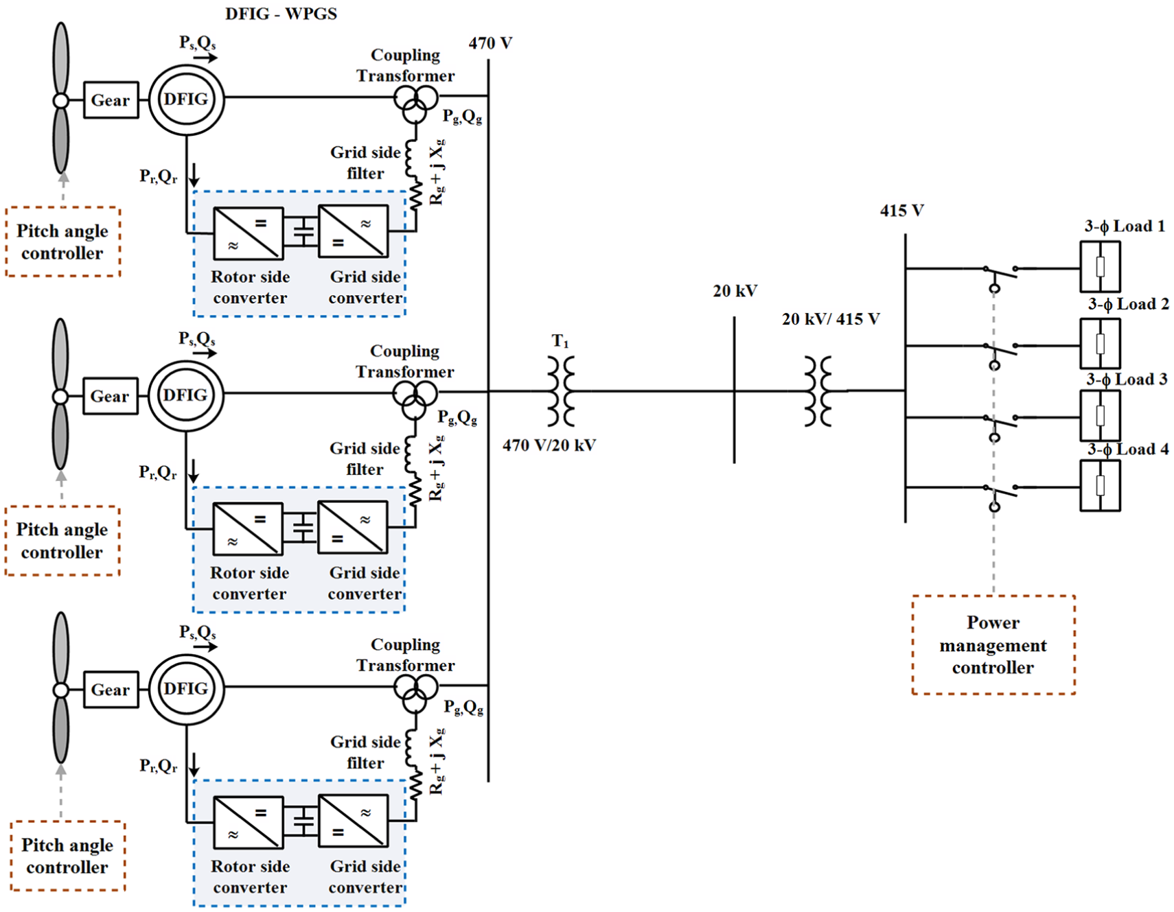
Schematic diagram of the grid-connected DFIG-WPGS.
Modelling of the WT
The wind energy is converted into mechanical energy by means of WT.1–5 The mechanical power generated by the WT is given as 9

where
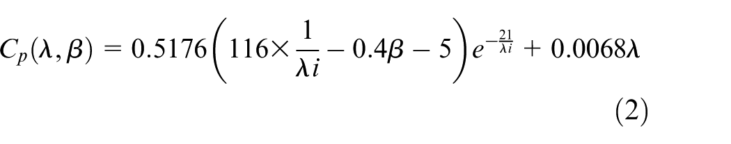
Equation (2) draws out the power efficiency of the WT, where Cp is a non-linear function of both tip-speed ratio (λ) and the blade pitch angle (β), where λ is the ratio of the turbine speed (

where
Modelling of the shaft system
A two lumped mass system is used as the shaft system of the WPGS. The coupled shaft is modelled as a spring and a damper. The equation for the shaft system is given as 17


where
Modelling and control of DFIG
The electric equations of the DFIG are written in the d−q oriented system according to the rotor reference frame 9


where rs and rr are the stator and rotor resistance, respectively;


where Ls, Lr and Lm are the stator leakage inductance, rotor leakage inductance and mutual inductance, respectively. 9 The per-unit electrical torque equation of the DFIG is given by

The active and reactive stator powers after neglecting the power loss is given as


A DFIG-WPGS has been coupled to the grid through back-to-back voltage source converter. The voltage source converter has been classified into rotor side converter (RSC) and grid side converter (GSC). 21 The RSC aims to maximize the output stator power by optimal control of rotor speed, thereby torque of the system is controlled and optimal power is extracted from the WPGS. Besides, the vector voltage command in d–q reference frame is obtained as the output signal from two PI-type controllers. These d–q axis voltage vectors are transformed into stationary reference frame and are used by the space vector pulse width modulation (SVPWM) to generate switching signals for the RSC. However, the aim of the GSC is to attain active and reactive power by controlling d-axis and q-axis current component, respectively. 22 Subsequently, Vdc voltage is injected along the d-axis component to control the active power of the WPGS. The reference voltage vector obtained from PI-type current control loop is transformed into stationary form and they are used by SVPWM to generate switching pulses for the GSC.
Proposed automatic power management controller
The schematic diagram of the proposed automated power management control strategy is shown in Figure 2. The power management system consists of four dynamic non-linear loads connected to the grid network by means of Boolean transfer static switch. The static switch utilizes 0/1 as the input, where 0 means OFF and 1 represents ON. The static transfer switch in the automatic power management system is used to manage the power to the loads. 18 This is operated based on the power measured from the WPGS and the load power measured from the dynamic non-linear load. The developed automatic power management system will decide itself by switching ON/OFF the load based on the load power requirement and the generated power of the WPGS. The automatic power management system employs a logical switch to manage the loads, and this logical switch is designed on the following condition:
Number of loads turned ON and their power requirement will be communicated to the WPGS.
If the bank is with poor power quality and major disturbances, then the load connected to the network will be isolated.
Automatic power management switch will be turned ON/OFF based on the load priority (load 1, load 2, …, load 4). However, load priority depends on the power required by the load.
In general, the power obtained from WPGS will be regulated to follow the power reference by controlling the blade pitch by means of pitch angle controller.
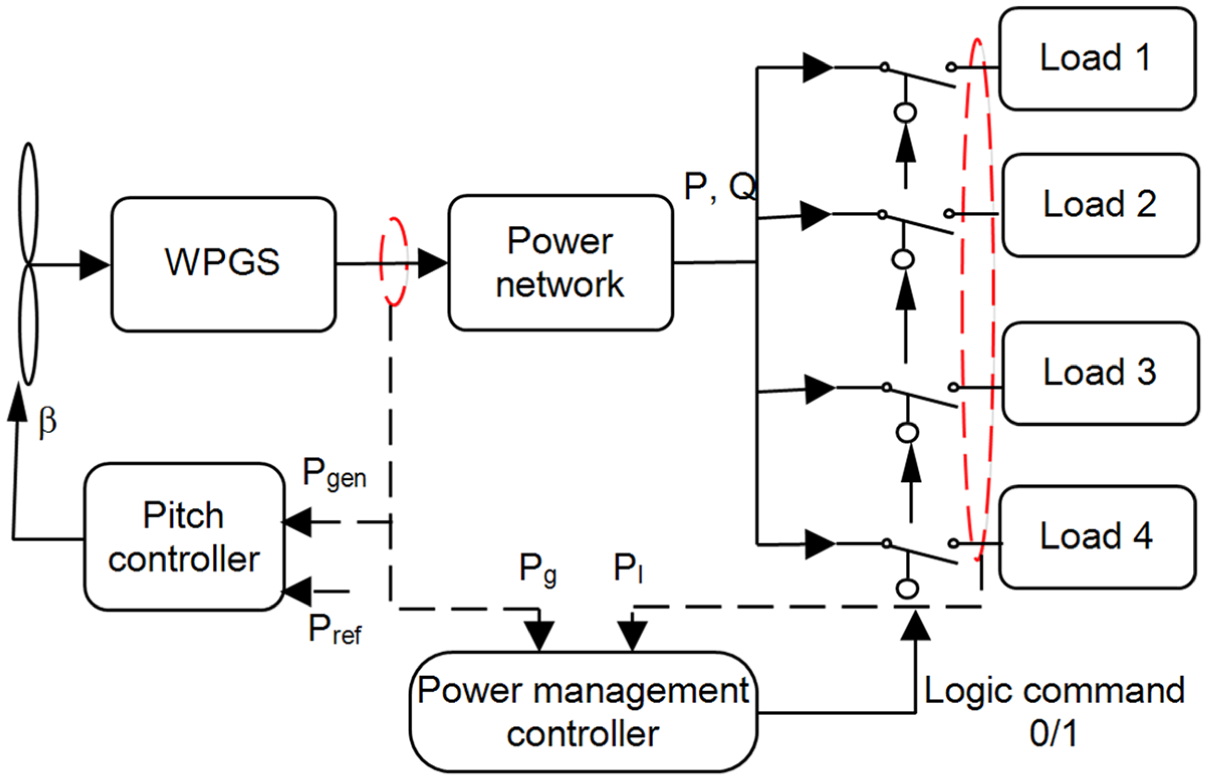
Control scheme of power management controller.
The logical switch has been developed on the basis of actual power generated from WPGS and power required by the load. The expression of the logical static logic switch is given as 19


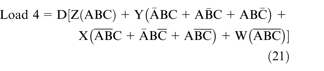
Here, all the quantities are expressed as logical variables in the condition ON = 1 and OFF = 0. There are four loads connected to the WPGS. The priority of the load is represented as n, that is, Loadn (n = 1:4). Based on the priority, the loads can be turned ON/OFF. There are four logical switches in the bank expressed as A, B, C, D and
Error tolerance of the power in the investigated system
The pitch angle controller adjusts itself to extract maximum power from the wind during huge fluctuation. Because of this instant variation of pitch, the measured power fluctuates around the power reference. Power reference obtained from the WPGS is used to build the automatic logical switch. 19 Therefore, the switching is based on the error difference between the measured power and reference power. The automatic switching state is based on the power error stated in the following condition:
If e = ‘positive’ then switch ‘ON’
If e = ‘negative’ then switch ‘OFF’


where e is the error; and Pg and Pref are the generated electrical power and reference power, respectively. From the condition, the automatic switch will turn ON when the generated power is larger than the reference power. However, the switch will turn OFF when the generated power is smaller than the reference power.
Proposed FLC-based pitch angle control system
Pitch angle controller is one of the effective methods to regulate the power of WPGS. 10 A fuzzy logic–based pitch angle controller is proposed to regulate the electrical power of WGS as shown in Figure 3. The pitch angle continuously changes according to the power measured from the WPGS. When high winds flow, rotor speed ωr gets increased, thereby producing high torque and improves the electrical output power. If the power exceeds the rated power or exceeds the load power requirement, the pitch controller feds the blade outward. Therefore, the wind striking the blade gets reduced and lowers the power production.
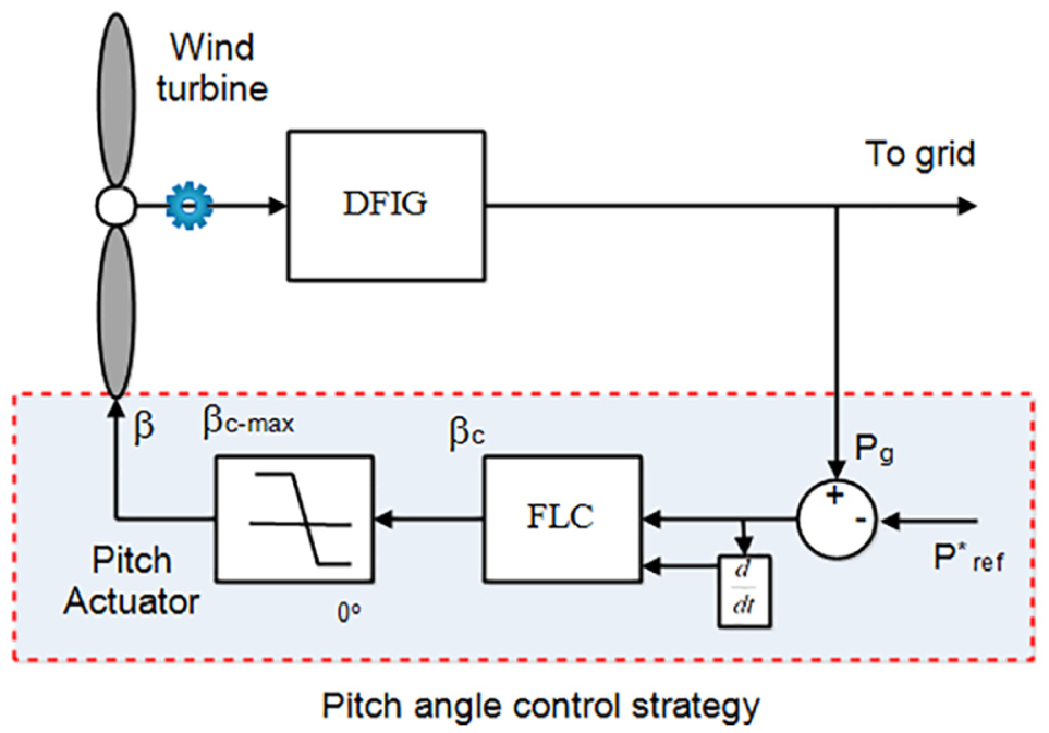
Block diagram of fuzzy logic–based pitch angle controller.
Consequently, when there is low wind flow. The electrical output from the turbine gradually decreases, but the power requirement of the load may be high. In order to satisfy the load requirement, the pitch controller commands the blade to fed inward of wind flow. So that maximum power from the wind can be extracted to satisfy the load requirement. Furthermore, the blades are feathered during emergency shutdowns to stop the power generation. Due to the continuous variation of wind, the pitch angle continuously changes, which could harm the pitch actuator, as it is often active. The pitch actuator restraints the performance of the WPGS based on the wind speeds.12–15 In this work, a suitable pitch control strategy is proposed to sustain the pitch angle at an optimal level all through the steady-state operation in order to decrease the action of the pitch actuator. To attain the command signal βc from the FLC, the variant e obtained from the difference between actual power and reference power and their change in time difference (Δe) obtained are fed as inputs to the fuzzy pitch controller. 22 The controller supplies control signal βc to the actuator which changes the pitch angle β.
Modelling of fuzzy logic control strategy
The fuzzy controller is a logical reasoning controller. The developed fuzzy logic–based pitch angle controller is shown in Figure 4. In order to obtain the command signal βc from the fuzzy controller, the variants e (i.e. Pg) and Δe (i.e. ΔPg) obtained from the power Pg and its corresponding reference power
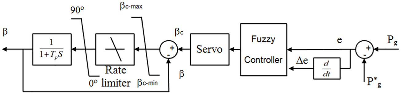
Pitch angle control strategy using FLC.
Fuzzification process
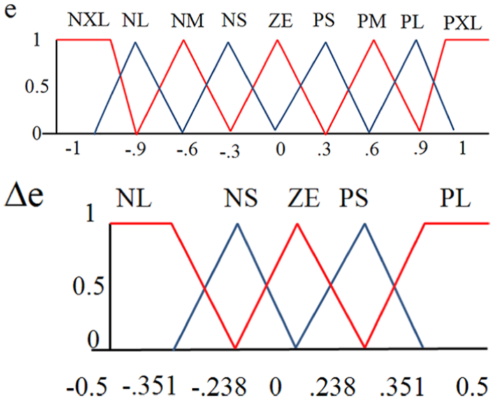
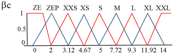
The fuzzy-based pitch controller is designed by triangular membership function with 50% overlapping. Figure 5 shows the input membership functions for both the cases of e and Δe. The triangular membership is selected for its faster process and smart implementation. The overlapping of the triangular membership function is more responsive when the variable approaches near zero. The linguistic variables of the fuzzy controller are represented by NXL (negative extra large), NL (negative large), NM (negative medium), NS (negative small), ZE (zero), PS (positive small), PM (positive medium), PL (positive large), PXL (positive extra large), ZEP (zero plus), XXS (double extra small), XS (extra small), S (small), M (medium), L (large), XL (extra large) and XXL (double extra large). The position of the input membership functions is obtained using Equation (24)

where z represents the value of the input variables, w is the width and m represents the coordinate point at which the grade of the membership function is 1.
Input membership function.
Fuzzy logic rule formation
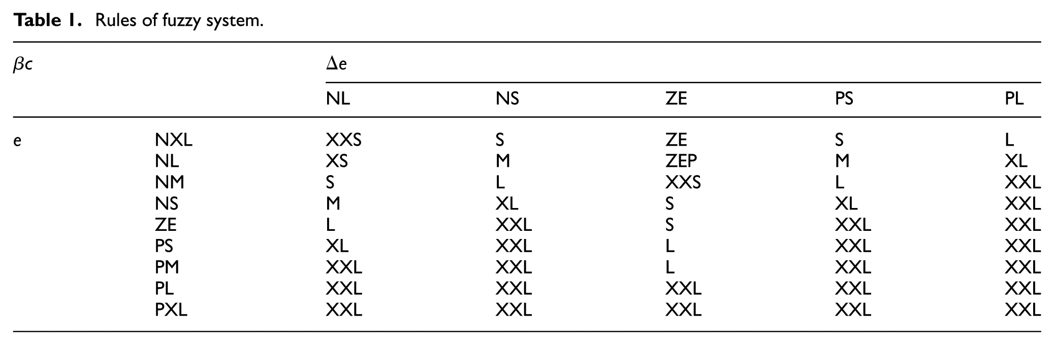
Designing standard logic rule is the key for obtaining a satisfactory control signal from the fuzzy pitch controller. The rules for the controller are framed by applying simple IF-THEN rules. The fuzzy control system has 45 rules, formulated and shown in Table 1.
Rules of fuzzy system.
Defuzzification process
The defuzzification process is a logic that reverses the fuzzification process. It converts all the fuzzy terms created by the rule base of the controller to the crisp terms and then sends them to the actuator of the WPGS. The defuzzification of the developed controller is shown in Figure 6. The output obtained is βc, which is fed to the pitch actuator. The response signal obtained from the fuzzy controller is very stable and the actuator system responses and varies the blade pitch angle depending on the βc obtained from the FLC. Furthermore, the weighing factor of the rule for the minimum operation is represented as 23

where μΔPg (ΔPg) and μδΔPg (δ(ΔPg)) are the triangular membership functions of the ΔPg and δ(ΔPg), respectively. The average weighted Wi of every rule output, which expresses the variation of the pitch angle reference βc, is calculated as 23

where Ni is the total number of rules and Di is the coordinate corresponding to the respective output or consequent membership function. The stability of the fuzzy pitch angle control system is guaranteed if the derivative of Lyapunov’s function is negative semi-definite in the active region of each fuzzy rule. 21 However, the stability issue is not investigated in detail since it is beyond the scope of this research.
Output membership function.
Power management using the proposed strategy
The control of the WPGS is done rather by mechanical controller devices or automatic power manageable control devices. Though, by analysing the alteration principle of the wind power, it is found that combined pitch and power management controller can regulate the produced wind power by regulating the angular rotational speed of the WT to optimum value.14–20 The equilibrium between the power production and power consumption of the load is achieved when the total power generated by WPGS is equal to the total load demand in addition to the power losses. The prediction of the wind speed all around year in particular site area could be easier to estimate the obtainable wind power from the wind farm and that could satisfy the load power constraints. By forecasting the demand and predicting the available power will be the proper way of planning the load constraints. The studied WPGS system consists of two control strategies, a mechanical pitch angle control for each WT and a power management control to manage total power demand and the available wind power. 27 Furthermore, combining both controllers has been discriminated as three functioning modes as shown in Figure 7.
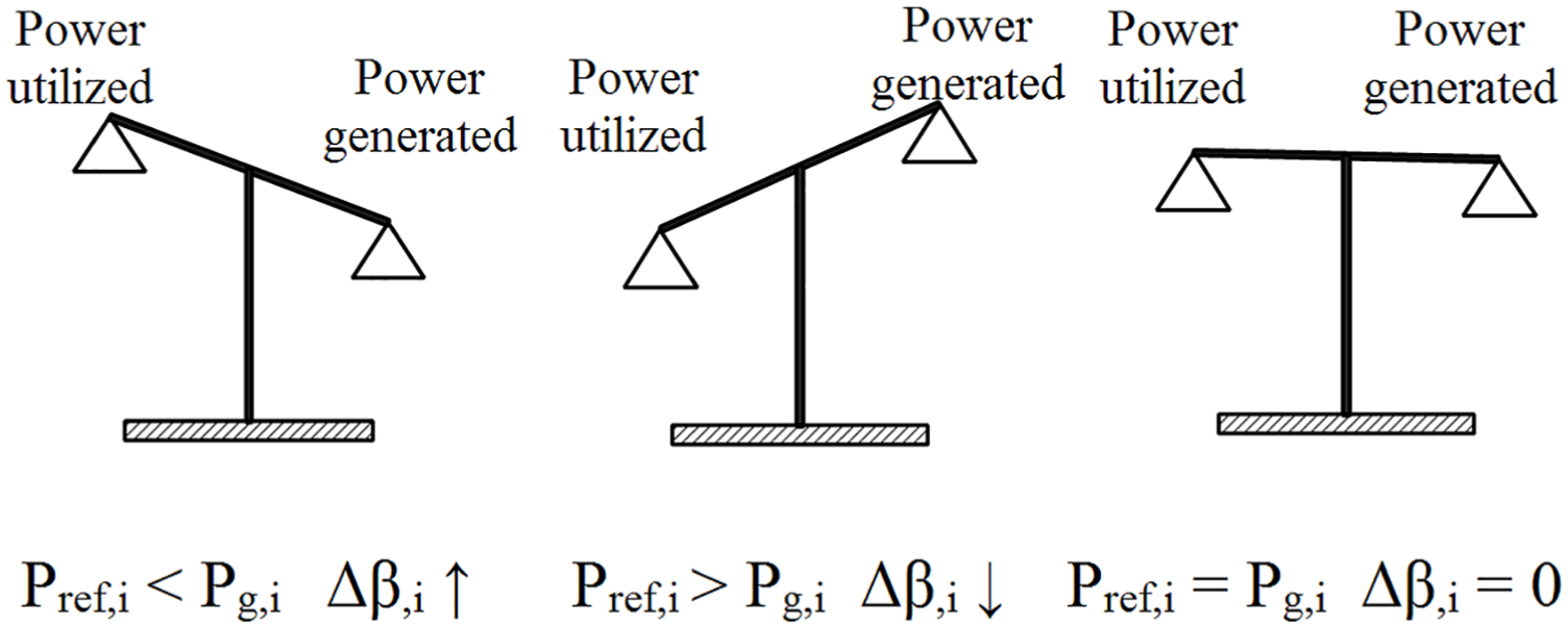
Pitch angle evolution according to generation and utilization.
If Pref,i < Pg,i then Δβ,i↑
In this case, the generated powers Pg,1,Pg,2 and Pg,3 are different. Here, the power delivered by the WPGS,i is higher than the power reference. In this condition, it is necessary to increase the pitch angle β, i in order to balance the production and consumption.
If Pref,i > Pg,i then Δβ,i↓
In this case, the generated power delivered by the WPGS,(1–3) is lower than the power reference. In this condition, it is necessary to decrease the pitch angle β, i in order to balance the production and consumption. During this condition, in some cases, the pitch angle β increases and decreases depending on the wind flow. The fluctuation in the wind flow can be seen in the power output. In such situation, the priority load is connected and demand is satisfied depending on the available power obtained.
If Pref,i = Pg,i then Δβ,i = 0
In this case, the power delivered by the WPGS,i is balanced with the power reference. In this condition, the pitch angle β = 0. The power generated is equal to the power required by the load. Again by variation in wind speed, the power generated may reduce. The load power requirement may increase and in this situation, the non-priority loads are disconnected to solve the power balance.
Simulation results and analysis
The proposed automatic power management coupled pitch control system is investigated for a 9-MW wind farm consisting of three variable speed WPGS. A complete grid-connected wind farm has been simulated using MATLAB/Simulink environment. In this model, the WGS consists of DFIG-WT connected to the power network. Furthermore, the particulars of the WT and DFIG are given in Appendix 1. The fluctuating wind speeds given to WTs are generated by means of computer simulation. Figure 8 shows three different wind speeds wind 1, wind 2 and wind 3 fed to WPGS-WT1, WT2 and WT3. The wind speeds flow at the mean value of 9–11 m/s.
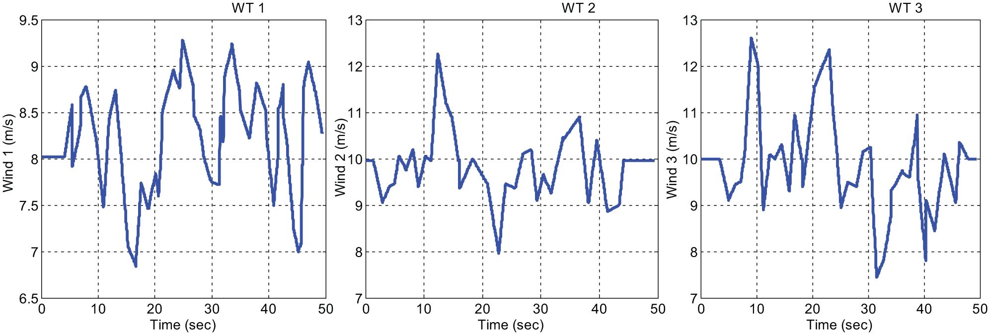
Simulated wind speed profile.
Consequently, to determine the performance of the proposed combined pitch controller and automatic power management switch, the analysis is carried out by three discriminate functioning modes. In this study, Loads 1 and 4 are considered as priority loads which are otherwise said as emergency loads that they should be always kept powered.
Case 1: when Pref,i < Pg,i
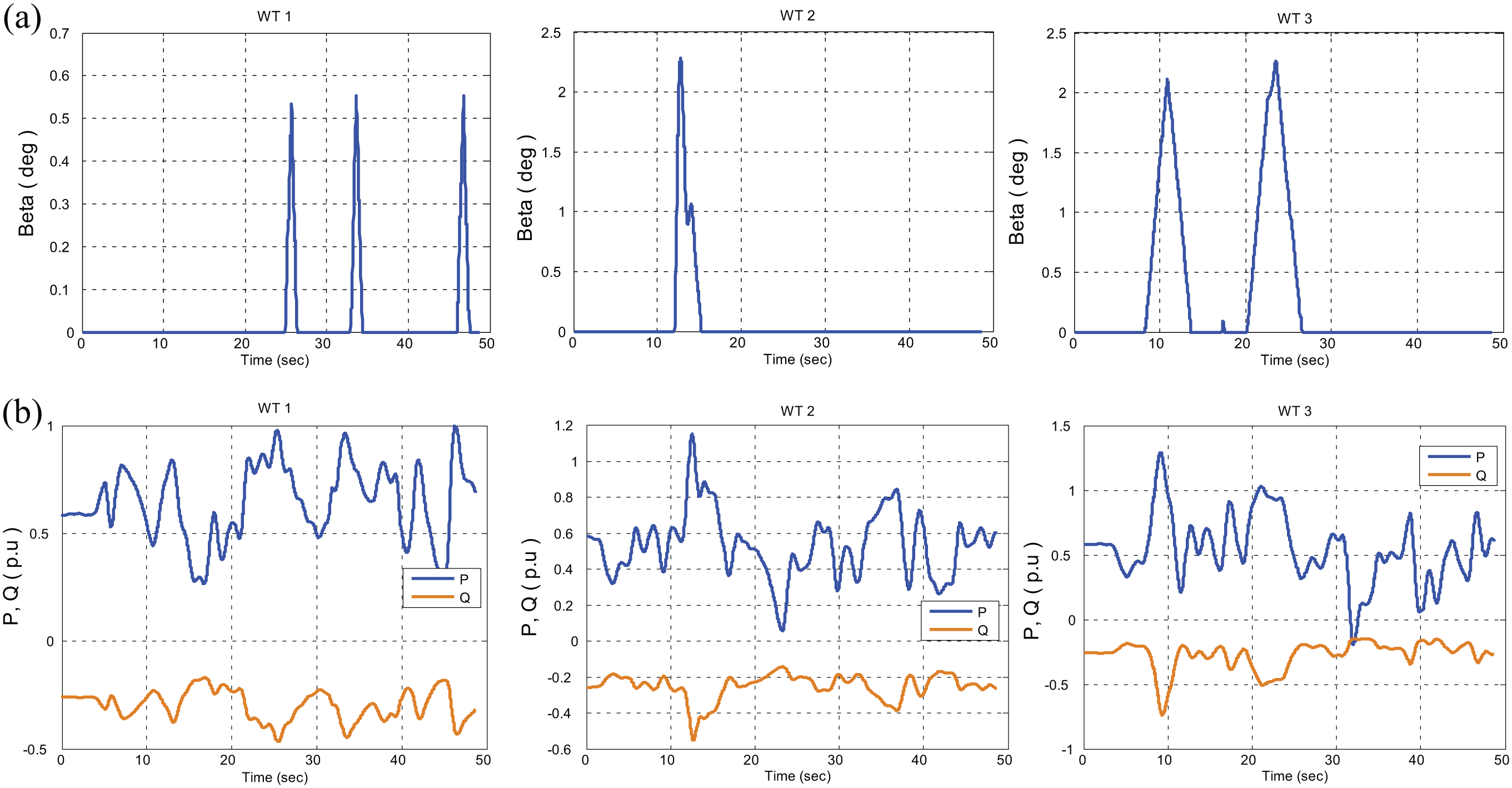
In this mode, power generated by the WPGS is higher than the load power requirement. It is because of high wind flow than the nominal value. Due to the flow of high wind gust, rotor speed rotates above the rated speed and produces high electrical power. But the load requirement is lesser than the power generated. During this circumstances, the pitch controller is employed to move the turbine blades outwards the wind to lower the power production. Figure 9(a) shows the pitch angle obtained from the pitch controller of three WTs. From that, it is observed that pitch angle increases from 2° to 7°. Therefore, the blade lowers and focuses towards the wind. Therefore, it reduces the power production.
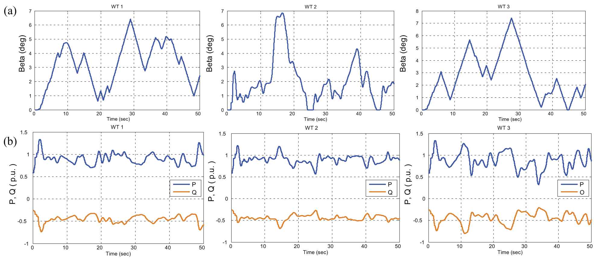
System behavior during Pref,i < Pg,i (a) Pitch angle b of WT1, WT2 and WT3; (b) real and reactive power of WGS obtained from WT1, WT2 and WT 3.
Figure 9(b) shows the active and reactive power generated by WT1, WT2 and WT3. It is observed that each turbine produces 3 MW of power. The error tolerance value obtained is positive. So, the automatic power management controller enables the entire load in 8 s. The total electrical power generated by WPGS is shown in Figure 10(a); it shows that the power produced is 8.9 MW which is comparatively higher than the load requirement. The logical controller switch ONs the entire load. The power utilized by the loads is shown in Figure 10(b). It is observed that all loads are fed with necessary electrical power.
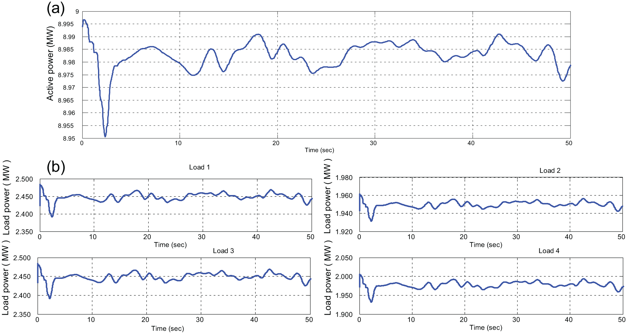
Load management during Pref,i < Pg,i (a) Total electrical power generated by WGS; (b) electrical power utilized by load 1, load 2, load 3 and load 4.
Case 2: when Pref,i > Pg,i
In this mode, power generated by the WGS is lower than the power required by the loads. It occurs due to the flow of low wind speeds. In such case, the rotor speed rotates below the rated speed and produces lower electrical power. The generated electrical power by the WGS cannot satisfy the load requirement. So that, pitch controller comes to active mode to maximize the power generation from the available wind. They use a memory unit controller to control the pitch actuator. That moves the turbine blades towards the wind flow which varies between 0° and 2° in order to maximize the power production of WT1, WT2 and WT3 as shown in Figure 11(a). The active and reactive power generated by WT1, WT2 and WT3 is shown in Figure 11(b). It is observed that the power production is lesser, which is about 1.5 MW per WT of the wind farm.
System behavior during Pref,i > Pg,i (a) Pitch angle b of WT1, WT2 and WT3; (b) real and reactive power of WGS obtained from WT1, WT2 and WT 3.
The total electrical power produced by the wind farm is shown in Figure 12(a). It is observed that the system produces only 6–6.8 MW of electrical power. But the load requirement is higher than the power generated. The power tolerance measured is negative, so power management disables non-priority loads 1 and 3 within 8 s. Furthermore, the power management controller enables the priority loads 2 and 4 to the wind farm. Figure 12(b) shows the power utilized by the loads; it is observed that loads 2 and 4 consume the available power and loads 1 and 3 are isolated from the network.
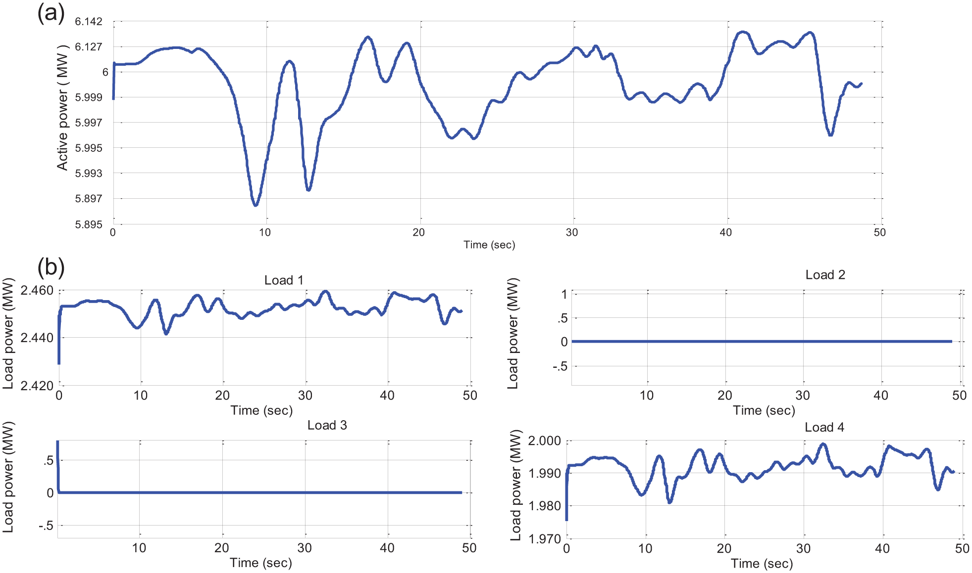
Load management during Pref,i > Pg,i (a) Total electrical power generated by WGS; (b) electrical power utilized by load 1, load 2, load 3 and load 4.
Case 3: when Pref,i = Pg,i
In this mode, power generated by the WPGS is in balance with the load power requirement. This is because of mean wind flow. The rotor speed rotates at the mean rated speed and produces electrical power. But the power generation of the WPGS depends on the load requirement. Figure 13(a) shows the pitch angle obtained from three WTs. From this, it is observed that pitch angle increases from 2° to 7° depending on the flow of wind. Figure 13(b) shows the active and reactive power generated by WT1, WT2 and WT3. It is observed that each turbine produces a nominal power of 3 MW.
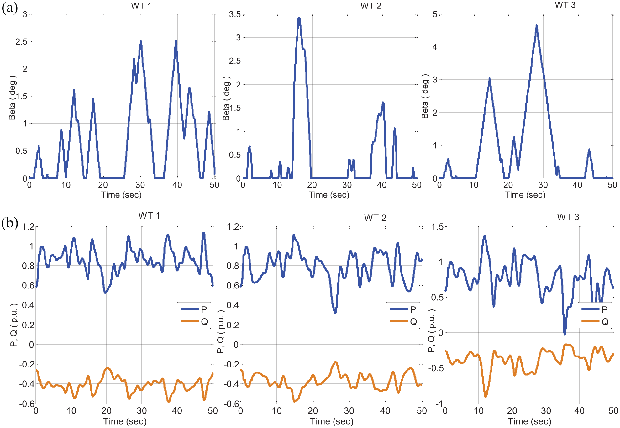
System behavior during Pref,i = Pg,i (a) Pitch angle b of WT1, WT2 and WT3; (b) real and reactive power of WGS obtained from WT1, WT2 and WT 3.
The total electrical power produced by WPGS is shown in Figure 14(a). It is observed that the power produced can satisfy the load requirement. The power tolerance measured is positive. Hence, the power management enables both the priority loads and non-priority loads. The power utilized by the loads is shown in Figure 14(b). The load consumes the same amount of power generated by the WPGS.

Load management during Pref,i = Pg,i (a) Total electrical power generated by WGS; (b) electrical power utilized by load 1, load 2, load 3 and load 4.
The proposed controller is studied for three functioning modes of WPGS. From those functioning modes, power generated and power utilized by the loads based on power requirement are analysed and presented in Table 2.
Comparative analysis of the developed pitch and static switch control strategy.
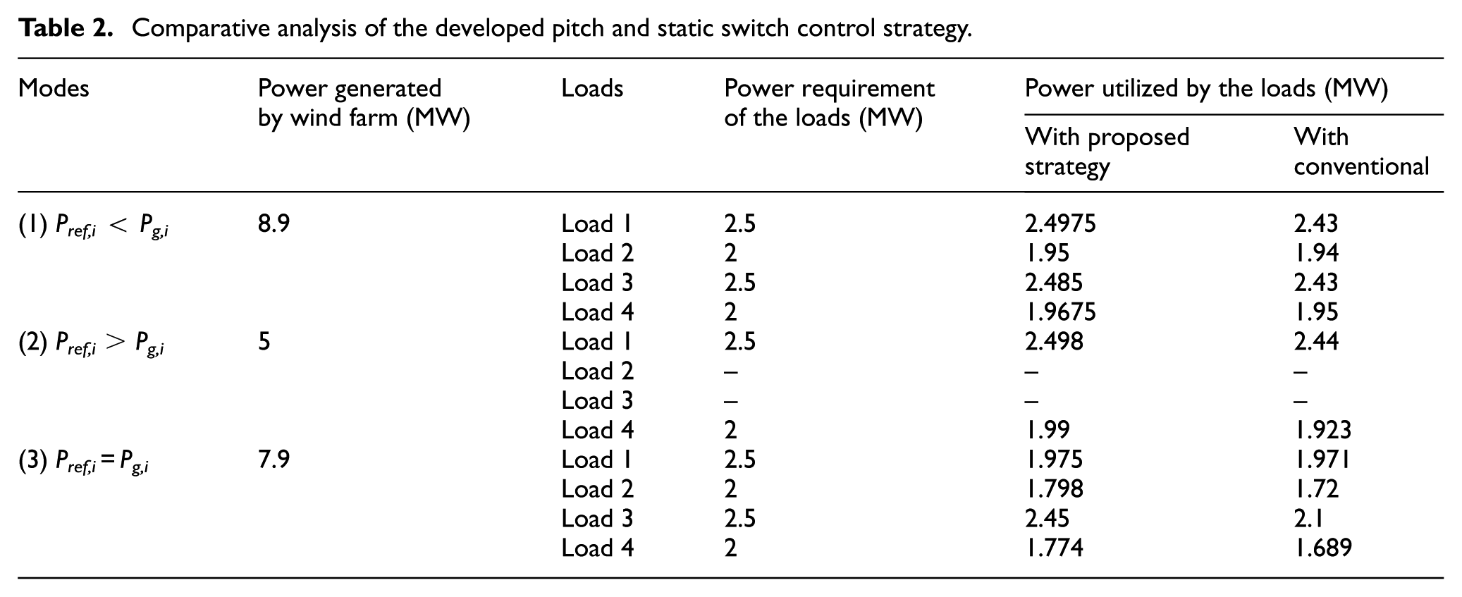
Table 2 shows the value obtained from the wind farm using the proposed control strategy and the conventional controller. The analyses are formulated for three functioning modes and the total power generated by the WPGS is given. During the first mode, the wind farm generates a power of 8.9 MW and power utilized by the load is 8.83 MW. In this case, all loads are connected to the wind farm. The power utilized by loads varies with time because they are dynamic in nature. Hence, the proposed controllers act accordingly and satisfy the load demand. In the second mode, the wind farm generates a power of 5 MW and power utilized by the load is 4.46 MW. Due to low power production, only priority loads are connected to the wind farm. Remaining loads are isolated by means of proposed power management controller. In the third mode, the wind farm generates a power of 7.9 MW and power utilized by the load is 7.53 MW. The power produced is utilized by the load. From the analysis, the pitch controller operates perfectly according to the variation of wind and the proposed strategy shows better result than the conventional strategy. Furthermore, the management control switches the loads based on their priority and power production.
Conclusion
The proposed method deals with the problem of balancing the electric power generated by the WPGS and electric power demand of the dynamic loads. The objective of this study is to ensure the required power to the loads. Therefore, a logical operated switch and a fuzzy logic–based pitch controller has been proposed. The logical operated automated switch is used to control loads based on their power requirement automatically. The logic expressions for switch have been developed based on the power generated from the WPGS and the power required by the loads, based on their priorities. Furthermore, the pitch controller performs effectively by extracting available power from the wind to balance the load power through a power management controller. This integrated operation ensures the objective of providing the required power to the load. The simulation results show that the proposed control strategies presume effectively by satisfying the total load demand from the generated power.
Footnotes
Appendix 1
Parameters of the wind generation system considered for the study is given in following tables,
Declaration of conflicting interests
The author(s) declared no potential conflicts of interest with respect to the research, authorship and/or publication of this article.
Funding
This research received funding from the Science and Engineering Research Board, Department of Science & Technology, Government of India (ECR/2017/000259).