
Abstract
Based on the theory of rack-gear common-tangential conjugate generating, the constructing of ease-off surface has been done by means of the topology modification of polynomial surface. By analyzing topological structure characteristics of ease-off surface, the meshing characteristics such as the contact area, the contact line, and transmission error are determined. By using the geometric analysis of ease-off surface and the potential energy method, the calculation methods of gear tooth stiffness and loaded transmission error are given, and a series of results for the tooth meshing stiffness, loaded transmission error, and load distribution map under varied loads are obtained. In order to solve the stress problem of tooth surface edge contact, the calculation method of quasi-Hertz contact is proposed by subdividing finite contact elements. Taking the second-order parabolic topological modification as an example, the time-varying history characteristics of tooth surface meshing are analyzed. The simulation results of the maximum contact stress and contact area are in good agreement with those calculated by MASTA software. Based on the integration of the geometric analysis of ease-off surface, the tooth stiffness calculation of potential energy method and the quasi-Hertz contact, it provides a convenient method for loaded tooth contact analysis.
Keywords
Introduction
Gear tooth contact simulation has become an indispensable technology for modern gearing design and its performance pre-control. In the 90s of the last century, TCA/LTCA (Tooth contact analysis/Loaded tooth contact analysis) technology was gradually applied in the design of complex tooth surfaces. 1 Later, TCA technology is used in the local synthesis method for the contact parameters at the reference point to realize the pre-control of tooth surface contact pattern and transmission error.1–3 Some researchers4,5 developed an ease-off surface analysis method that is more suitable for numerical calculation. Fan 6 presented ease-off and its application in TCA for face-milled and face-hobbed spiral bevel and hypoid gears. Based on ease-off and sensitive matrix, many researchers7–11 proposed an optimization design method for spiral bevel gears to ensure the meshing performance. Wei et al.12,13 developed the ease-off analysis method based on the isometric transformation, and further proposed a calculation method for the machine-tool settings of spiral bevel gears by the surface synthesis. Using TCA and ease-off surface topology, Jiang et al. 14 studied the design and implementation of the modification of high-order transmission error helical gears.
The calculation methods of gear tooth stiffness mainly include Ishikawa formula of material mechanics, PEM (potential energy method) of elastic mechanics and FEM (finite element method), etc. Due to the rigidity of FEM, it is difficulty to achieve a parametric modeling. Base on PEM, Chaari et al. 15 conducted stiffness analysis on spur gears by combining five kinds of deformation potential energy: bending, shearing, radial compression, Hertz contact, and wheel body. Wang and Zhang 16 established a meshing stiffness model considering tooth lead modification of spur gears by PEM. Compared with FEM, the solved relative error of PEM does not exceed 5%,15,16 and the calculation efficiency is much higher than that of FEM. Chen and Shao17,18 proposed a new nonlinear excitation coupling analytical model considering meshing stiffness and transmission error, and analyzed the influence of gear tooth error and tooth profile modification amount on meshing stiffness. Xie and Shu 19 proposed a meshing stiffness model considering the coupling flexibility of the adjacent teeth and tooth profile error. By the cumulative integral PEM, Wan et al. 20 derived the time-varying stiffness of helical gears, and analyzed the effects of modulus, number of teeth, and tooth width on stiffness. Chang et al. 21 proposed a linear programming method based on finite element method and elastic contact theory to calculate meshing stiffness. Wei et al. 22 proposed a general analytical calculation method for the helical gear meshing stiffness, and established a nonlinear excitation calculation model coupling the gear tooth error and meshing stiffness, and the influence of different modification parameters on the meshing stiffness of helical gears was studied. Liu et al. 23 gave a modified algorithm for calculating the meshing stiffness of helical gears when the root circle does not coincide with the base circle.
Although the ease-off surface has been widely used in the three-dimensional topology design of the tooth surface, the topology mapping and meshing analysis of the ease-off surface are insufficient, especially the integration with LTCA is not enough. Based on the ease-off surface topology, the calculation of gear stiffness is a problem that must be solved in the development of LTCA method. In view of this, based on the principle of common-tangential conjugate mapping of rack-gear, the ease off surface is constructed by a second-order polynomial modification surface. Based on the meshing information contained in ease off, the time-varying meshing stiffness algorithm is studied, and the loaded transmission error and load distribution characteristics are obtained. At the same time, for solving the tooth surface stress when edge contact occurs, a line contact method of quasi-hertz unit is proposed, so that the LTCA calculation of the modified gear is completed efficiently and conveniently.
Rack generation and topology modification
Tooth surface equations generated by the rack
The cylindrical gear is generated by the envelope of the rack, and the surface of the rack is expressed as a two-order polynomial:

where, u and v are the lengthwise direction and the tooth profile direction respectively, as shown in Figure 1. The coefficients a1, a2 are used to control the shape of the surface in the u-direction and the v-direction respectively, and a3 is used to control the torsion of the surface.

Coordinate systems for common-tangential rack to generated gears.
The common-tangential relation between rack and generated gear is shown in Figure 1, S0(O0-x0y0z0) is the rack coordinate system, Sd(O-xdydzd) is the fixed coordinate system, S(O-xyz) is the generated gear coordinate system. The original point O0 of S0 is the pitch point of the rack and cylindrical gear at the initial position. During movement the rack always keeps a common-tangential relationship to two surfaces of pinion and gear, where α-angle of the plane π to y0-axis is the pressure angle of rack, β-angle of the plane π to x0-axis is the spiral angle. Taking formula (1) as the rack surface, the equation of helical rack surface is as follows:

Where, the rotation transformation matrix

When the coefficients of polynomial (1) take different values, different effect of topology modification will be formed on the tooth surface of cylindrical gear.
By using coordinate transformation, the position vector and normal vector equations of the cylindrical gear can be obtained as

Where, the coordinate transformation matrix

When the formula (1) is a plane, equation (3)
By deducing the meshing equation between rack and gear, the meshing rotation angle of gear can be determined as
Where, r1 is the pitch circle radius of the generated gear, and ny and nz are the components of the normal vector
Setting method of ease-off topology
The modification value of tooth flank is regarded as the separation errors of the corresponding points on the modified tooth surface Σ(i) and the standard involute tooth surface Σs in the normal direction, it is expressed as

where i = 1, 2 represents the pinion and the wheel respectively. As shown in Figure 2, the modified tooth surface Σ i and the standard involute tooth surface Σs are mapped as ease-off(i).

Mapping relationships of two ease-off surface.
Since the left and right sides of the rack plane Σ0 are respectively tangent to the pinion Σ1 and the wheel Σ2, the three surfaces are in a common-tangential relationship (Figure 1), thus the one- to-one mapping relationship of Σ1 − Σ0 − Σ2 can be determined. Taking the rack plane Σ0 as the mapped coordinate plane (u, v), the isometric mapping of ease-off(1) and ease-off(2) can be constructed. By directly doing the algebraic sum of the error values of the corresponding points on two surfaces of ease-off(1) and ease-off(2), the off-value of any mapping point on two meshing tooth surfaces can be determined as

By plotting the off-value zd of grid points, the ease-off surfaces of wheel and pinion can be obtained as in Figure 3.
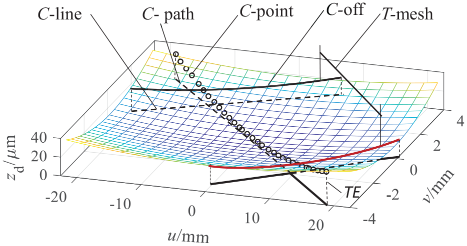
Ease-off for gear surface.
The above method is based on the mapping principle of common-tangential conjugation, and its advantage is that the ease-off surface can be constructed conveniently without solving meshing equation.
For the contact line (C-line in Figure 3) of tooth surface, the synthetic curvature can be represented directly by the off-value of ease-off surface (C-off in Figure 3), which provides the convenience of data calculation for TCA/LTCA (loaded TCA) and avoids solving complex nonlinear equations.
Meshing characteristics of tooth surface
The topology control parameters
Taking a gear pair as an example, the parameters of blank are listed in Table 1.
Parameters of gears.

The contact pattern of tooth surface is designed to be 80% of the tooth profile and tooth width, the shape control parameters are as follows
Tooth profile direction:
Tooth lengthwise direction:
The thickness of coating: d = 0.006 mm
Taking a02 = 2.08 × 10⁻⁵, a20 = 0.0015
After calculation, the obtained ease-off surface is shown in Figure 3.
Geometric analysis of ease-off surface
Based on the characteristics of the ease-off surface topology, some contact characteristics such as contact line, contact off-line, and contact path are obtained.
For equation (4), any rotation angle φ corresponds to a series of (u, v), and a series of off-value zd in Figure 3. Traversing the rotation angle φ, the family of contact off-lines (C-off in Figure 4) is obtained, express as


Waterfall plot of contact off-lines.
Here i, j represent the serial number of C-off lines and the serial number of points on the C-off line respectively.
When a series of C-off lines are tangent to the projection plane, they can be drawn as a waterfall drawing of C-off lines shown in Figure 4. A series of contact points constitute the contact path (C-path in Figure 3), which represents the process of tooth surface from meshing-in to meshing-out. The vertical height value zs of the waterfall plot represents the clearance of the instantaneous contact line at any position.
The vertical height value of C-point on the ease-off surface (Figure 3) represents the transmission error (TE) of this meshing point, which is extracted as the off-value zd of all C-points from 1 to 34 to be plotted the TE curve as shown in Figure 5. The three curves of TE separated by a tooth meshing period (

Graph of TE/LTE.
From the above analysis, we can see the relationship between the off-value zd(i,j) at any position on ease-off surface, the clearance dj of C-off line and the TE

Mesh stiffness calculation and LTCA
PEM calculation of tooth stiffness
According to the helical gear slicing model, one of the sections is taken as the tooth profile unit of the spur gear. Along the tooth profile direction, with v as variable, the tooth profile is divided into n units of width Δy. Change the position of force F (point M in Figure 6) and calculate the stiffness value of this position. In the Figure 6, Sz and ly are the distances from point M to the symmetry line of tooth profile and the tooth root circle respectively, and the pressure angle.

Slicing model of tooth stiffness.
The gear meshing stiffness includes five parts according to the PEM
15
: bending stiffness k1, shear stiffness k2, axial compression stiffness k3, blank body stiffness k4, and Hertz contact stiffness kc. Connecting the stiffness of each part in parallel, the slicing element meshing stiffness of the gear pair is obtained, denoted as

Where, p and g represent the pinion and the wheel respectively. The stiffness components are calculated respectively for the pinion and the wheel. The formulas of numerical integration are as:

where, the calculation formula of body stiffness k4 is detailed in reference,
19
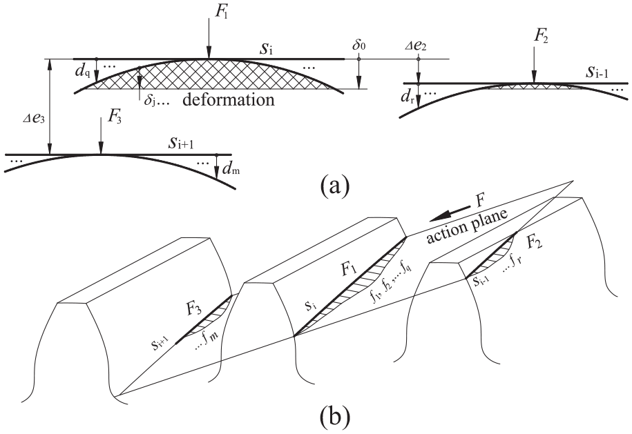
Model of multi-tooth load: (a) model of error and deformation and (b) model of force distribution.
Traverse the variable vi∈[vmin, vmax] (i = 1, 2, …n), the time-varying stiffness matrix of the tooth profile can be obtained:

Compared with the spur gear, the C-line of the helical gear is inclined, so the corresponding stiffness of each point at the C-line is different. Discrete any C-line into several elements as shown by si in Figure 7, any element maps a segment of tooth profile, and the corresponding stiffness
The number of slice elements of teeth affects the calculation accuracy. When the number of longitudinal slices reaches 50 and the number of height cells reaches 20, the element size is 0.9 × 0.5 mm, and the calculation results are basically stable. Considering the calculation accuracy and solution efficiency comprehensively, 90 × 25 elements with the size of 0.5 × 0.4 mm are selected. In the subsequent calculation, the element of contact line takes a higher precision, with a width of 0.2 mm.
Model of LTCA
Assuming the length of the contact line elements is Δl, and the corresponding stiffness of pinion and gear is denoted as

Where j represent any elements of contact lines.
Due to the modification of the tooth surface, there is clearance dj at all positions of the contact line except for the top point. Under the action of load, the deformation develops from small to large, gradually eliminating the contact clearance until m elements contact to share the total force F (Figure 7). Assuming that the normal deformation at the top point on the contact line of present tooth is δ0, then the displacement at other positions can be expressed as (δ0 − δj).
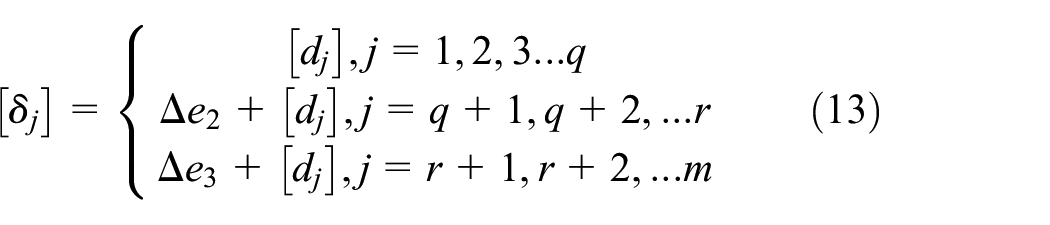
For potential multi-tooth contact areas (Figure 7), there will be multi line of contact simultaneously. For an example of the three-teeth contact, there may be three line of contact, si−1, si, and si+1 shown in Figure 7. For multi-tooth contact, the contact sequence of the elements on the contact lines si−1 and si+1 of the prior and next teeth pair should be considered. Count the relative value Δe of TE into the clearance of contact lines si−1 and si+1 (Figure 7), thus the contact error of the elements on these contact lines can be determined as δ = Δe+ d. For three lines of contact, assuming that the number of contact elements of si is from 1 to q, that of si−1 and si+1 are respectively from (q + 1) to r and from (r + 1) to m, then at least (the number of elements with) m ≥ r ≥ q ≥ 1 is required, so the array of contact error is expressed as:
For the meshing of three pairs of teeth, the total force is shared by three lines of contact as

The equation of compatibility between force and deformation is

Where K1, K2, K3, Δ1, Δ2, Δ3 are the stiffness array and deformation array of three lines of contact, respectively.
Equation (15) is merged as

Where force and stiffness and error array of contact lines are


Assume that the total number of elements in contact is m, the equation of compatibility between force and deformation is as

Obviously, when

At first, the number m of actually contacted elements is determined by equation (18), and then their corresponding meshing stiffness K can be determined as

The load sharing ratio of the present tooth, prior tooth and the next tooth are respectively as

Traversing a contact period Tm according to the above process, a series of K(ϕ), δ0(ϕ), F(ϕ) with different rotation angles ϕ are obtained.
For any instantaneous angular position ϕ on the C-path, the LTE is

The above method of formulas (1) to (20) gives a full numerical LTCA calculation flow from ease-off surface to TCA parameter analysis without solving nonlinear equations.
Example of TCA
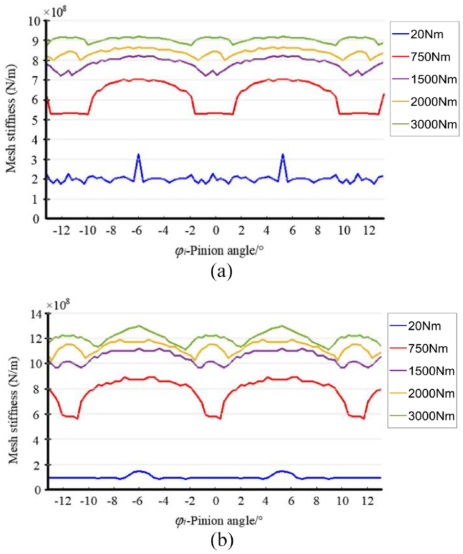
Take the load torque of wheel: T2 = 20, 750, 1500, 2000, 3000 Nm. The obtained meshing stiffness and loaded transmission error LTE at any contact position are shown in Figures 5 and 8. Under these five loads, the fluctuation of LTE and the corresponding stiffness excitation are the smallest when T2 = 750 Nm. This is coincident with the engineering application experience: the gear transmission is most stable under low-medium loads. As the load increases, the period shared by 2 or 3 teeth increase, and the actual contact ratio of the tooth surface increases. Nearly full load at 3000 Nm, the contact ratio is 2.38.

Mesh stiffness.
The load sharing ratio λ of the tooth is shown in Figure 9, and the part with load sharing ratio of 1.0 is the single tooth contact area. Under the load of 20 Nm, there are a few double-teeth meshing zones: [−5.715°, −4.972°], [4.571°, 5.314°], and a large part of the tooth surface is not involved in meshing (the part before −5.715° and after 5.314°). As the load increases, the number of contact teeth pairs gradually increases. When T2 = 3000 Nm, the maximum load sharing ratio of gear teeth is 0.91.

Load sharing ratio between teeth.
Figure 10 shows the load distribution of contact lines at 16 positions under 2 and 3 kNm loads. Figure 10(a), under 2 kNm, the load is mainly distributed in the middle part of the tooth surface, and the maximum distributed force fj is 80.8 N. Figure 10(b), under 3 kNm, the tooth surface is fully loaded, the maximum force fj is 107.3 N in the middle, and the tooth surface is in edge contact.
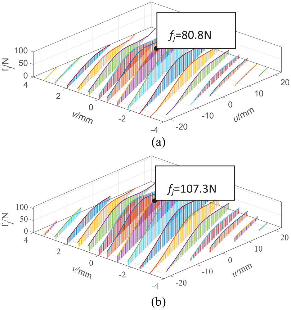
Load distribution of tooth surface: (a) load 2 kNm and (b) load 3 kNm.
Calculation of quasi-Hertz point contact stress
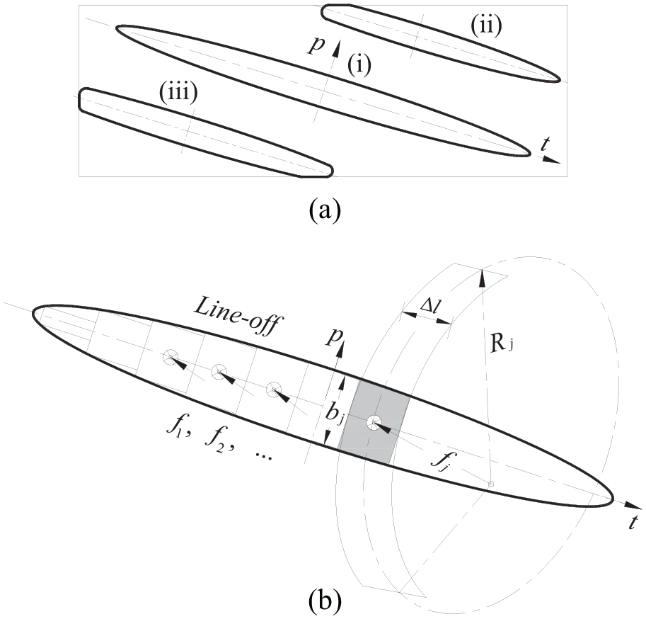
The contact strain area of the tooth surface at any instantaneous is generally a long and narrow ellipse (Figure 11(a) (i)). When the tooth surface is in edge contact, stress concentration occurs at the edge, and the instantaneous contact area is distorted. The distortion of ellipse with edge contact at one end shown as in Figure 11(a) (ii), the distortion of ellipse with edge contact at two ends shown as in Figure 11(a) (iii). Under a lower load, the force is distributed in the middle of the tooth surface, and the contact area is elliptical. The calculation of contact stress can be carried out with the Hertz elastic strain model of point contact. Under heavy load, the edge contact occurs, and the contact area is distorted (Figure 11(a) (ii) or (iii)). This is a contact problem of finite boundaries that cannot be directly calculated by the Hertz model of point contact. In view of this, a quasi-Hertz contact method that uses discrete finite element to fit the contact area is proposed, as shown in Figure 11(b), where the contact area is divided into finite line contact elements.
Hypothesis schematic of instantaneous contact deformation area: (a) Hypothesis form of contact deformation on tooth surface and (b) finite elements of quasi-Hertz contact area.
Since the load distribution along the length of the contact line is already known as shown in Figure 10. Regardless of the shape of the contact area, it can be assumed to be a finite number of cylinders with length of Δl (seen in Figure 11(b)). According to the topology of the ease-off surface, each pair of elements is regarded as the Hertz contact of the cylinder with the plane. Since Δl is small, the action force of element is considered to be uniformly distributed:

The cylinder is in Hertz contact with the plane, and the largest contact stress (MPa) at the middle point is:

Half-width of contact area (mm):

Stress distribution along the width direction of the contact area:

where, Rbj is the radius of the cylinder element, which is the normal synthetic curvature radius in the direction perpendicular to the contact line.
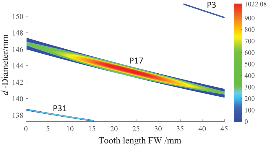
Thus, the stress distribution matrix σφ [σ1, σ2, σϕ … σµ] of any contact line is obtained. By interpolating and encrypting the stress matrix, the contact stress nephogram in Figure 12 can be plotted, which shows the three contact lines p3, p17, p31, corresponding to the three stress and strain states of the instantaneous contact lines (ii), (i) and (iii) in Figure 11(a). Three kinds of contact states where just reflected prove that quasi-Hertz contact method can solve various contact problems of tooth surface.
Instantaneous contact stress of 2 kNm.
By solving each contact line, the stress distribution matrix of each point on the tooth surface can be obtained, the contact stress nephograms of tooth surface are drawn in Figures 13 and 14. Where the stress distribution on the tooth surface is obviously gradient, which is the same as the aforementioned ease-off surface (Figure 3).

Contact stress contour of 2 kNm.

Contact stress contour of 3 kNm.
Comparison of simulation results
Use MASTA software to simulate and compare with the above calculation results. MASTA software has two calculation methods: the finite element method (denoted as MASTA-FE) is to analyze the full 3D finite element model of the gear and calculate it in combination with the Hertz contact formula; the slicing method (denoted as MASTA-SE) is based on ISO 6336 standard, 24 using a simple sheet model of gear (Smith 25 ) for calculation. The calculated LTE is seen in Figure 15, mesh stiffness seen in Figure 16, instantaneous contact stress seen in Figures 17 to 19.

LTE simulation by MASTA: (a) LTE in MASTA-FE calculation and (b) LTE in MASTA-SM calculation.
Mesh stiffness simulation by MASTA: (a) Mesh stiffness in MASTA-FE calculation and (b) mesh stiffness in MASTA-SM calculation.

Instantaneous contact stress of 2 kNm (MASTA): (a) MASTA-FE calculation result and (b) MASTA-SM calculation result.

Contact stress contour of 2 kNm (MASTA): (a) MASTA-FE calculation result and (b) MASTA-SM calculation result.

Contact stress contour of 3 kNm (MASTA): (a) MASTA-FE calculation result and (b) MASTA-SM calculation result.
Meshing stiffness and LTE simulation
Comparing the LTE of Figures 5 and 15, and the meshing stiffness of Figures 8 and 16, it can be seen that: the LTE in Figure 5 is consistent with MASTA-FE in Figure 15(b) in change trend, and is closer to the calculation result of MASTA-SM in value in Figure 15(a). On the contrary, from the change trend, the stiffness lines of Figure 8 are consistent with MASTA-SM in Figure 16(a), and from the numerical point of view, it is closer to MASTA-FE in Figure 16(b).
Simulation of contact stress nephogram
Comparing the three simulation results of contact stress nephogram in Figure 12 and MASTA ( Figure 17(a) and (b)), it can be seen that their shapes of the instantaneous stress-strain nephograms are basically the same, the maximum stress values are closer, and the calculation result of MASTA-SE in Figure 17(a) is relatively small.
From the contact stress nephograms of the full tooth surface, under 2 kNm the maximum stresses calculated by the quasi-hertz contact method (Figure 13), MASTA-FE and MASTA-SM (Figure 18) are 1022.08, 1011.80, and 884.09 MPa, respectively, and the errors are 1.0% and 15.6%. From the above three nephograms, it can be seen that the tooth surface strain is concentrated in the middle, and the edge of the tooth surface is almost non-contact. Under 3 kNm the stress concentration occurs at the edge, which is consistent with the load distribution reflected in Figure 10. The maximum contact stresses calculated by the aforementioned three methods (Figures 14 and 19(a) and (b)) are 1198.35, 1136.21, and 995.97 MPa, respectively, and the errors are 5.5% and 20.3%.
Comparing the above simulation results, the results of the method in this paper are closer to those of finite element method in MASTA-FE. Due to the different gradient control methods of tooth surface modification, there is a slight difference in the shape of the stress nephogram, but the overall results are in good consistency. The presented method is better than MASTA-SM in calculating accurate and are more prior to FEM in calculating efficiency and convenience. The combination of ease-off surface analysis and PEM stiffness calculation can more accurately carry out the LTCA of gears, overcoming the problem that conventional methods cannot accurately consider the three-dimensional topological modification of gear tooth surface.
Conclusion
This paper presents a simulation method of ease-off surface based on the equal-tangent conjugate of rack-gear and polynomial topological modification. Based on this geometric analysis, the calculation methods of meshing stiffness, loaded tooth contact analysis and stress-strain of quasi-Hertz contact are proposed. The main conclusions are as follows:
Using the polynomial surface, the shape and properties of complex tooth surface topology modification can be easily controlled, and the problems in conventional modification control methods, such as excessive parameters and complex surface reconstruction can be avoided.
Based on the theory of rack-gear common-tangential conjugate generating, the numerical tooth surface and ease-off surface model can be constructed accurately, and the geometric analysis data can be directly used for the loaded tooth contact analysis (LTCA).
Based on the geometric analysis of ease-off surface, the time-varying meshing stiffness, loaded transmission error, and load distribution can be easily obtained by using the potential-based slicing method, and the parameterization of the LTCA is easily realized. The problems of solving nonlinear equations, finite element modeling, and huge computation are avoided.
Using discrete elements of the contact area, the calculation method of quasi-Hertz contact proposed can well solve the stress and strain of the tooth surface in edge contact. Compared with the finite element calculation results of MASTA software, the consistency is good.
Footnotes
Acknowledgements
The authors sincerely thanks to everyone in the gear group of Henan University of Science and Technology for his critical discussion and reading during manuscript preparation.
Handling Editor: Chenhui Liang
Author contributions
The author’ contributions are as follows: Bing-Yang Wei was in charge of the whole trial; Jia-Qi Li wrote the manuscript; Xue-Mei Cao, Chun-Yang Han were responsible for the simulation analysis with MASTA software.
Funding
Supported by National Natural Science Foundation of China (Grant No. 51875174), and Postgraduate Education Reform and Quality Improvement Project of Henan Province (Grant No. YJS2022JD12)
Availability of data and materials
The datasets supporting the conclusions of this article are included within the article.