
Abstract
To analyze the influence mechanism of pitch deviation on cylindrical helical gear meshing stiffness and vibration noise, the calculation methods about meshing stiffness and engaging vibration of helical gear which consider actual pitch deviations are proposed. The numbering rules of gear meshing teeth in LTCA (Load Tooth Contact Analysis) were rearranged according to the contact ratio and tooth pitch deviation, and the time-varying meshing stiffness and the axial degree of freedom were considered in the helical gear vibration model. A numerical simulation of example based on helical gears with the given pitch deviation is performed, which proves that load transmission error and RMS (root mean square) value of meshing vibration acceleration with tooth pitch deviation are bigger than that with standard pitch. The percent deviation of meshing stiffness increased with the increase in contact ratio, but decreased gradually with increase in load. The resonant frequency of vibration acceleration with pitch deviation becomes smaller comparing to the frequency with standard pitch. This study provides evidence that it is essential to consider the influence of pitch deviation when we design the parameters and predict vibration of cylindrical helical gear transmission system.
Keywords
Introduction
Cylindrical gears are widely used in automotive transmission system, especially in hybrid systems, and vibration and noise of gear transmission system largely determine the quality of integrated hybrid powertrain system. There are many factors that affect the vibration and noise of the cylindrical gear transmission systems, which can be broadly divided into three categories: tooth meshing frequency, rotational frequency of gear shaft, and frequency components of random excitations. Time-varying meshing stiffness, as an unavoidable internal incentive factor that affects vibration characteristics of cylindrical gear system, requires an adequate attention in the process of gear dynamic design; however, the periodic function of time-varying meshing stiffness is always treated as a single-frequency component of tooth meshing frequency. Kiekbusch et al. 1 built the minute two- and three-dimensional finite element models which can be used to solve the torsional meshing stiffness through the application of ANSYS Parametrical Design language (APDL). Pedersen and Jørgensen 2 have suggested that there are two factors affecting the meshing stiffness, first the boundary condition through the gear rim size included in the meshing stiffness calculation and second the number of the contact teeth. Rincon et al. 3 calculated the meshing stiffness of cylindrical involute gear in double contact period on account of the coupled deflection of adjacent contacting gear pairs. A correctional mathematical model for simulating gear root crack with linear expand path of a driving gear is developed by Zhou et al., 4 in which a modified static energy method is used to compute the time-varying meshing stiffnesses of the meshing gear pair.
Pitch deviation (also called tooth spacing errors) is defined as the difference between the actual pitch and the nominal pitch, and it reflects the uneven distribution of the gear teeth relative to the rotational axis. The existence of the deviation of tooth pitch affects the working stability of gear transmission system. Hayashi and Hayashi 5 presented the formulas of the pitch errors which are induced from the Fourier expansion formula that expresses the transmission error of a gear, and then, the meanings, problems, and utilities of the pitch errors are studied with these formulas. A theory is put forward by Handschuh et al. 6 that tooth root stresses are directly related to the spacing error, and the analytical formulations that came from this theoretical system allow the confirmation of the stress magnification coefficient due to a certain scope of pitch error deflection as well as the quantitative method for how much pitch error can be able to endured within the stress limit defined by the user. Each tooth pitch error of a spur gear pair was considered separately by Ghosh and Chakraborty, 7 and the simulation results indicate that if properly modified, the vibration caused by tooth surface geometrical errors like profile and spacing error can be reduced considerably.
In the existing literatures, the pitch deviation of each tooth pair is almost considered separately, that is to say, there is not enough attention paid to the mutual coupling effect of the pitch deviations of the adjacent mesh tooth pair at the same time. Due to the existence of the pitch deviation, the gear meshing stiffness is not a single frequency of tooth meshing cycle, but the combination of tooth meshing frequency, gear shaft frequency, and synthetic pitch error frequency.
The aim of this work is to propose a methodology to systematically analyze the influence mechanism of pitch deviation on cylindrical helical gear meshing stiffness and vibration noise. And it is organized as follows: The first segment aims at reviewing the published literatures on the influence of pitch deviation on gear transmission, especially for the influence of transmission stability. In order to solve the problem of considering the mutual coupling effect of the pitch deviations of the adjacent mesh tooth pair, the LTCA method for helical gears with tooth pitch deviation is designed in section “LTCA model for helical gear consideration of tooth pitch deviation.” The meshing stiffness of helical gear is derived from the LTCA model which considered pitch deviation in section “Influence of tooth pitch deviation on meshing stiffness,” and the meshing stiffness values under various torques and contact ratios are compared. Then, upon the vibration model which considers the time-varying meshing stiffness excitation, the simulation results and discussions about the vibration characteristics of the helical gear system with or without pitch deviations are exhibited in section “Influence of tooth pitch deviation on meshing vibration” which is followed by conclusion in section “Conclusion.”
LTCA model for helical gear consideration of tooth pitch deviation
Pitch deviation is defined in the tangential direction of end pitch circle face, and its numerical value is the algebraic difference between the actual pitch and the theoretical pitch. 8 The deviation value is positive when actual tooth pitch is greater than the theoretical pitch and negative on the contrary. Figure 1 is the schematic diagram of cylindrical gear tooth pitch deviation, where pt is the theoretical tooth pitch and fpt is tooth pitch deviation.
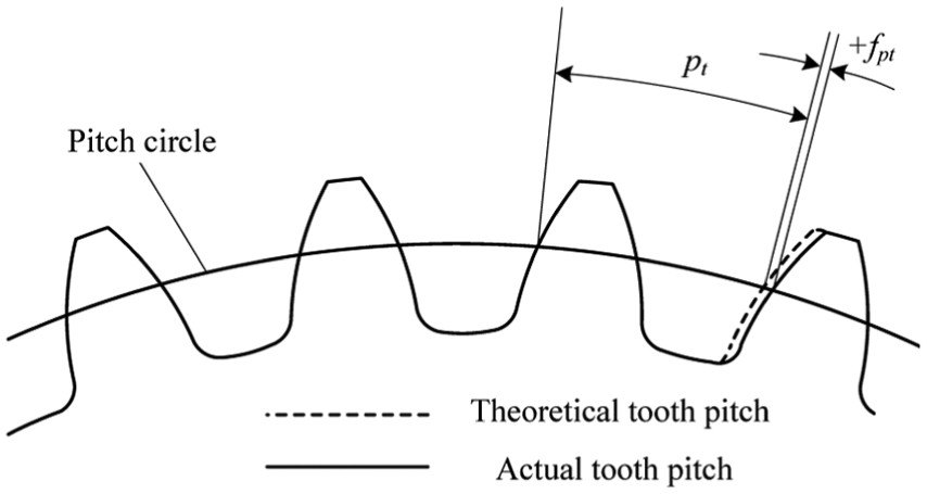
The schematic diagram of cylindrical gear tooth pitch deviation.
Because the pitch deviation of LTCA program is measured in the direction of the meshing normal line, it is necessary to convert the original pitch error value to the normal direction according to the following equation (1)

where fpbn is the pitch deviation in the direction of the meshing normal line, αt is the pressure angle of end face, and β is the spiral angle of helical gear.
Loaded tooth contact analysis technology of helical gear was first systematically proposed by Zhang and Fang 9 in 1999. On this basis, an improved helical gear model for loaded tooth contact analysis considering pitch deviation is shown in Figure 2, where every three pairs of meshing teeth, denoted by I, II, and III, are in contact at a specific instant among the meshing cycle. The tooth surface curve of meshing gear in Figure 2 is in the normal plane along the relative principal direction. And ik (k = I, II, and III) denotes the meshing contact point and jk denotes a point along the relative principal direction.

Helical gear model for loaded tooth contact analysis.
It is noteworthy that the initial tooth clearance with pitch deviation is different from the standard tooth surface. And before the deformation of meshing tooth occurs, the clearance between driving tooth surface and driven tooth surface along the relative principal direction can be calculated by a column vector

where matrix [
Under load P, the driving tooth surface undergoes displacement Z and the contact load becomes redistributed due to tooth deformation. The equilibrium state of force after deformation can be described by the following equations


where matrix [
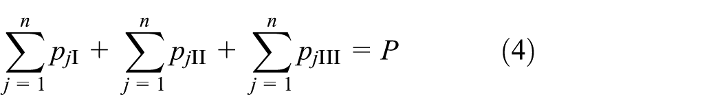
If the each of the teeth pitch deviations is the same, then the equations (3)–(5) can be solved by linear programming method,10–12 and the complete loaded contact process of helical gear can be obtained. However, in practice, the teeth pitch deviations are not always the same.
In order to calculate the complete LTCA process which considers actual tooth pitch deviation, let N be the minimum integer which is larger than the theory contact ratios of gears. Numbering rule of meshing teeth pairs in Table 1 reflects the complete engagement processes of tooth pair N, and equations (3)–(5) are solved for N times, and then, the complete LTCA results of tooth pair N from entering to exiting the meshing processes are obtained by merging the data of the first meshing period of each group.
Numbering rule of meshing teeth pairs.

Calculation and simulation of a living example are carried out by the basic parameters of helical gear pair in Table 2 and the pitch deviation values in Table 3.
The basic parameters of helical gear pair.

The pitch deviation values of the given teeth pairs.
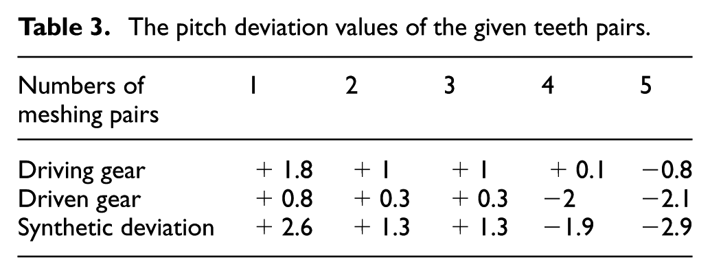
The theoretical contact ratio of helical gear pair in Table 2 is 2.2, and the maximum number of meshing teeth pairs is 3. In order to obtain the results of the third tooth pair from entering to exiting the meshing processes, teeth pairs with pitch errors of 3-4-5, 2-3-4, and 1-2-3 are analyzed by the LTCA program.
Figure 3 indicates that the load distribution coefficient value of the first contact point reduces to zero, which results in the decrease in real contact ratio than that in theory. Load transmission error with tooth pitch deviation is bigger than that with standard pitch in Figure 4, and the characteristic of strict meshing tooth cycle frequency is also changed for the existence of pitch deviation.
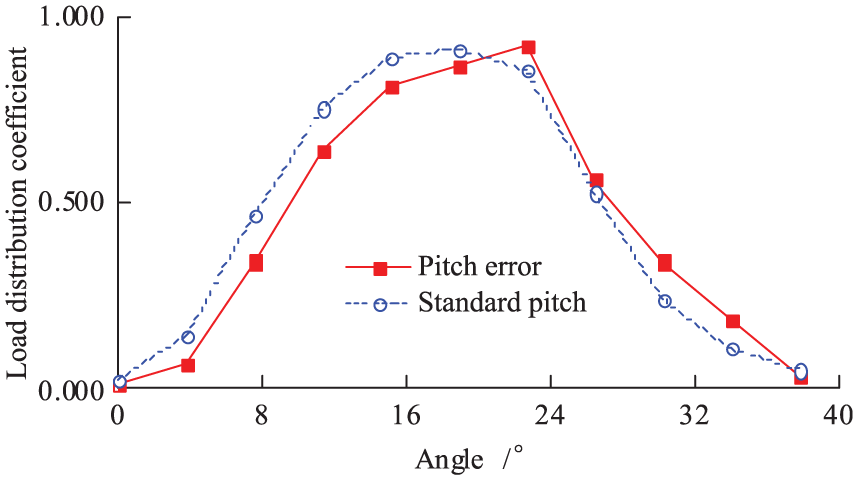
Comparison of load distribution coefficients.
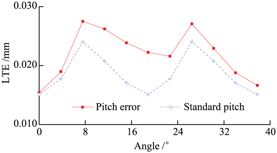
Comparison of load transmission errors.
Influence of tooth pitch deviation on meshing stiffness
In the presence of the tooth pitch deviation, the contact condition between the tooth surfaces is changed, and the comprehensive meshing stiffness of the gear pair with pitch deviation is different from that with the standard pitch.
The meshing stiffness of helical gear can be obtained by equation (6)

where Tm is the load torque, mn is the normal module, and z2 is the teeth number of driven gear.
Time-varying meshing stiffness of the complete synthesized pitch deviation period is calculated according to the measured pitch deviations of helical gear in Figure 5 and the basic parameters of helical gear pair in Table 2.
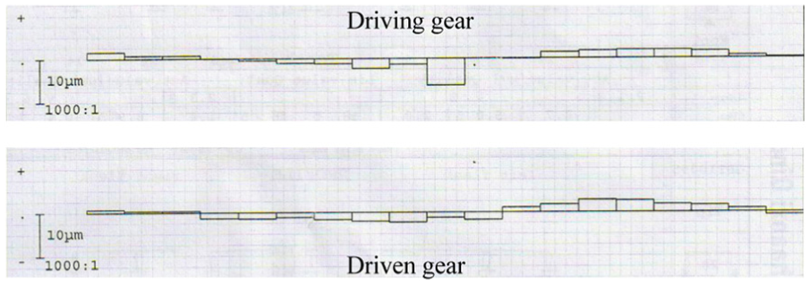
The measured pitch deviations of helical gear.
It is shown from simulation results in Figure 6 that meshing stiffness of helical gear with pitch deviation is lower than that with standard pitch, and the maximum percentage of deviation reaches 24%, and this is mainly because of the decrease in gear contact ratio.

Meshing stiffness comparison of helical gear (tooth width: 75 mm).
In order to compare the influence of the pitch deviation on the meshing stiffness under different contact ratios, let theoretical contact ratio increases from 2.2 to 2.4 with the growth of tooth width from 75 to 100 mm in Figure 7, and then, meshing stiffness is increased compared to Figure 6. And the maximum percentage of deviation reaches 28% in Figure 7, which is bigger than 24% in Figure 6.

Meshing stiffness comparison of helical gear (tooth width: 100 mm).
For a more comprehensive analysis of the influence of pitch error on meshing stiffness deviation under different contact ratios, the maximum deviation of meshing stiffness under different contact ratios is given in Figure 8. It can be seen that the deviation rates are increased with the increase in contact ratios, that is to say, high contact ratio requires high accuracy of pitch error.

Comparison of meshing stiffness deviation under different contact ratios.
The meshing stiffness of helical gear is usually considered as a linear characteristic; in other words, it is independent of the changes in load torque; however, the gear contact pattern clearly indicated that the tooth contact ellipse will expand with the increase in load. And also, some teeth are not on the actual contact under light load due to pitch deviation, and it is necessary to compare the average meshing stiffness of helical gears under different loading conditions.
It can be seen in Figure 9 that average meshing stiffness of helical gear with pitch deviation is 1.49E9 N/m under the load of 1325 N m, which is reduced by 9.3% comparing to 1.35E9 N/m of standard pitch. The mean value of the meshing stiffness of the helical gear with the tooth pitch deviation is always lower than that of the standard pitch helical gear, and the average percent deviation of meshing stiffness decreases gradually with the increase in load and finally decreases to a stable value.

Comparison of average meshing stiffness under different loads (tooth width: 75 mm).
Influence of tooth pitch deviation on meshing vibration
The meshing performance of helical gear get better with increasing the spiral angle of helical gear; but at the same time, the axial force will also be increased.12–15 Therefore, it is necessary to consider the axial degree of freedom when establishing the vibration model of helical gear. The helical gear vibration model with six degrees of freedom is established as Figure 10, and it is a two-parameter (stiffness and damping) model with torsional and lateral vibration, which means that it includes both the linear and rotational equations of the system’s motion. In this study, the driving and driven gears are all supported by the tapered roller bearings for resisting the axial forces of meshing tooth pairs.16,17
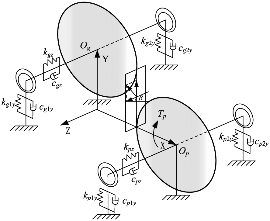
The helical gear vibration model with six degrees of freedom.
According to Newton’s law, 18 dynamic equations of system can be obtained as equations (7) and (8). The focus of this article is to analyze the influence of tooth pitch error on meshing vibration; therefore, the vibration directions of the shaft, such as bending and shimmy, are neglected


where yi, zi, and θi (i = p, g) are the vibration displacements and the vibration angles at the points of Op and Og; mp, mg, Ip, and Ig are the mass and inertia of driving and driven gear; Rp and Rg are the pitch radii of driving and driven gear; cpz, cgz, kpz, and kgz are axial equivalent damping and stiffness at the points of Op and Og; Tp is the input torque of driving gear; and Tg is the output torque of driven gear.
cpy, cgy, kpy, and kgy are radial equivalent damping and stiffness at the points of Op and Og

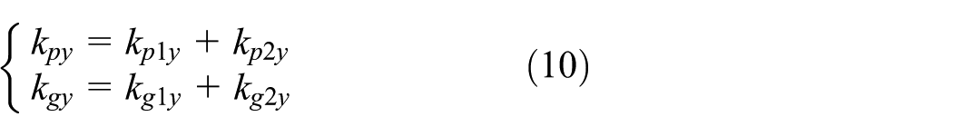
where cp1y, cp2y, cg1y, and cg2y are radial support damping of left and right bearings and kp1y, kp2y, kg1y, and kg2y are radial support stiffness of left and right bearings.
Fn are the dynamic normal meshing force of the meshing teeth
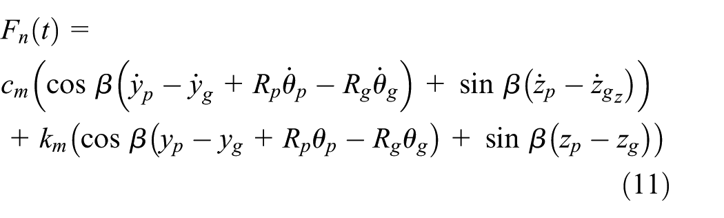
where km(t) is the time-varying meshing stiffness of helical gear and cm is the meshing damping of helical gear.19–21
The simulation data from Figures 11 and 12 show that the vibration noise of helical gear with pitch deviation is obviously bigger than that with standard pitch under the given conditions. The RMS value of meshing vibration acceleration in Figure 11 is 72.71 m/s 2 under the influence of pitch deviation, which is bigger than the value of 68.51 m/s 2 under the standard pitch. Figure 12 also indicates that the components of meshing vibration with pitch deviation not only contain tooth meshing cycle frequency and corresponding harmonic frequencies but also modulation side-bands of synthetic pitch error frequencies.22–23

Comparison of vibration acceleration in time domain.

Comparison of vibration acceleration in frequency domain.
It can be clearly seen from Figure 13 that the vibration acceleration peaks with pitch deviation move to the negative direction of horizontal axis comparing to the peaks with standard pitch, and this is caused by the decrease in meshing stiffness, and then, the resonance frequency is reduced.
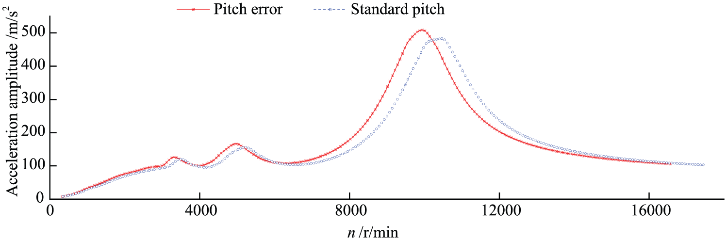
Comparison of vibration acceleration under different rotational speeds.
Conclusion
This article has provided a series of appropriate models to analyze the influence mechanism of pitch deviation on cylindrical helical gear meshing stiffness and vibration noise. The models consist of the improved LTCA model considering actual pitch deviations and a 6-degree-of-freedom discrete vibration model of helical gear pairs. The gear meshing number rules of LTCA were rearranged according to the contact ratio and tooth pitch deviation. The excitation of cylindrical helical gear vibration model including time-varying meshing stiffness and the axial degree of freedom was considered. An example set of analyses were performed to point various unique features of helical gear transmission system with pitch deviation, and from the computerized simulation and comparison of the pitch deviation and standard pitch, some conclusions can be drawn as follows:
Simulation results show that the tooth surface load distribution is changed because of the existence of the tooth pitch deviation, which reduces the actual gear contact ratio. Comparing with the gear with standard pitch, load transmission error with tooth pitch deviation is increased, and the characteristic of strict meshing tooth cycle frequency is changed by the pitch deviation of gear pairs.
The existence of gear tooth pitch deviations makes the changes in contact condition of the meshing tooth surfaces and the comprehensive meshing stiffness of the gear. Meshing stiffness of helical gear with pitch deviation is lower than that with standard pitch, and the maximum percentage of deviation reaches 24% under given working conditions. The percent deviation of meshing stiffness increased with the increase in contact ratio, but decreased gradually with increase in load.
The RMS value of meshing vibration acceleration with pitch deviation is 6.1% greater than that with standard pitch, and in frequency domain, the components of meshing vibration with pitch deviation not only contain tooth meshing cycle frequency and its harmonic frequencies, but also modulation side-bands of synthetic pitch error frequencies. The resonant frequency of vibration acceleration with pitch deviation becomes smaller comparing to the frequency with standard pitch, and this is mainly caused by the decrease in the meshing stiffness of the teeth pairs.
Footnotes
Academic Editor: Haiping Du
Declaration of conflicting interests
The author(s) declared no potential conflicts of interest with respect to the research, authorship, and/or publication of this article.
Funding
The author(s) disclosed receipt of the following financial support for the research, authorship, and/or publication of this article: This work was supported by China Postdoctoral Science Foundation (No. 2017M611710), Jiangsu 333 Project (No. BRA2016445) and National Science and Technology Major Project (2017YFB0103200).