
Abstract
The numerical analysis of the impact of a hollow droplet on a solid concave obstacle at various heights of the edge wall and impact velocity is presented in this study. The Volume Of Fluid (VOF) approach was used to simulate hollow droplet impact using OpenFoam software. The Newtonian, incompressible, and laminar properties of the glycerin hollow droplet are assumed. Hollow droplet collision hydrodynamic behavior and jet characteristics were explored. The height of the counter jet rose as the impact velocity and height of the edge wall increased. Maximum height and length have happened to case 8 in t = 2 ms and case 3 in t = 1 ms, so the amount of it is 9.75 and 19.75 mm, minimum height and length in the last time computed is 1.4 and 2.73 mm for cases 1 and 7, respectively.
Keywords
Introduction
The impact of a hollow droplet on a solid concave obstacle with a sharp edge at various impact velocities was investigated. It’s used in a variety of industries, including plasma coating, spray painting and coating, and nanofiber bubble electrospinning. The concave surface’s shape and curvature are critical in the aforementioned industrial applications. Many research has looked at how a droplet behaves after impact on various shapes and types of surfaces.
Experiments and analytical models have been used to study the dynamics of a single droplet impingement. 1 Researchers have done some studies on droplet contact and adhesion on a solid surface. 2 The influence of a droplet adhesion on a flat surface was studied experimentally by scientists to investigate the fluid jet that occurs at the surface. 3 Researchers conducted experimental and computational investigations of the influence of a droplet on a wetted surface. 4 Double droplets impacting on the surface with varied impact velocities were studied numerically. 5 Scientists experimented to see how a hollow droplet interacts with the surface and the morphology of its behaviors. 6 Scientists computed the solidification of hollow droplets on the surface at varied impact velocities and shell thicknesses. 7 The influence of glycerin and diesel hollow droplets with varied dynamic contact angles was numerically simulated by the researcher. 8 Multiple droplets impingement in an ink-jet printed process was simulated using a Lattice Boltzmann simulation. 9 Using the coupling Volume Of Fluid (VOF) method, several researchers simulated the coating of pipe with molten droplets. 10 Using a 3-D model, scientists numerically investigated the impact and solidification of a molten tin droplet on another formed frozen splat. 11 Heat transfer and energy conversion12–14 were studied in the channel and on the surfaces15,16 with a different structures.
In this paper, a hollow droplet of glycerin was mathematically simulated impacting with varied velocity onto various curvatures of the concave obstacle. Hollow droplets collide on a concave obstacle with varying edge wall heights. In addition, the impact velocity is adjusted depending on how the jet fluid is generated on the surface. In this article, the morphology and diagrams of the jet fluid parameters after impact are used to examine dynamic behavior and jet fluid attributes.
Problem definition
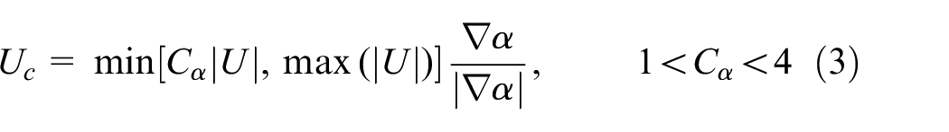
In this study, a hollow droplet is defined as a glycerin shell fluid including an air cavity. Following impact, a hollow glycerin droplet collides with a solid concave obstacle with a sharp edge, and the hydrodynamic behavior and phase transition are explored. It is assumed that the fluid is Newtonian, incompressible, and laminar. The outer diameter (D) of a hollow droplet is 5.25 mm, while the air diameter (d) is 4 mm. Table 1 shows the material characteristics information. 17 Figure 1 shows the computational domain and concave obstacle dimensions, with the length of the concave surface (L) assumed to be 10 mm and the height of the edge wall (h) varying for each case, as indicated in Table 2. As a result, Figure 1 shows the gravitational acceleration (g), the initial velocity of a hollow droplet (U), the boundary condition, and the hollow droplet’s initial position. In terms of contact angle analysis, the contact angle created on the hydrophobic surface should be such that the total surface energy of the solid-liquid interface exceeds that of the solid-gas and liquid-gas interfaces. At the time of the droplet’s interaction with the hydrophobic plate, the contact angle is equal to 140°. Each instance is characterized in Table 2 by the height of the edge wall (h) and the impact velocity (U).
Material properties data.


Schematic diagram of the computational domain.
The height of the edge wall at a different impact velocity for each case.
Simulation methodology
Volume of fluid
The impact of a hollow droplet on a concave mounted obstacle was simulated using the Volume Of Fluid (VOF) approach. This approach involves calculating a single set of momentum equations to track the interface between a fluid droplet and an air cavity. By determining the volume percent of fluid in the control volume, the VOF approach captures the interface. When the cell includes simply air, the value is zero; when the cell contains material, the value is one; and when the cell has a fluid interface,

To obtain the correct curvature at the contact, an accurate estimate of fluid volume fraction distribution is required. As a result, at the interface between the two phases, proper discretization of the displacement term on computational cells is critical. Poo and Ashgriz 18 investigate the approach in this research, in which a displacement term is introduced to the volume fraction distribution equation as follows 19 :

The additional third term in equation (2) induces interface compression, which convinces the conversion of each phase’s volume fraction and its boundary at the interface. In this case, is the proper velocity for proper interface compression, as determined by equation (3). 19
The volume fraction averaged continuum density in each control volume can be calculated according to the fraction of the droplet fluid (α). 2

The “d” stands for the droplet, while the “a” stands for the air phase. The other volume fraction averaged attributes work in the same way. 2

The VOF model conservation equation may be expressed as follows, provided the fluid is Newtonian, incompressible, and laminar 20 :

The momentum equation for the incompressible flow is as follows 20 :
The force at the border between the droplet and the surrounding gas is included in the term
Using that phrase, the surface tension on the interface of the two phases is calculated and is considered perpendicular to the surface.
Mesh convergence
The impact of a hollow droplet on a concave mounted obstacle is simulated in two dimensions. In the impact region, an adaptive intensifying mesh is applied. To verify mesh independence, the grid spacing is reduced until no significant change in the Newtonian droplet form occurs. Mesh elements size decreased from 0.5 to 0.1 mm, and Newtonian droplet shape compared together until reached the best mesh sizing. The total grid number is 7500,
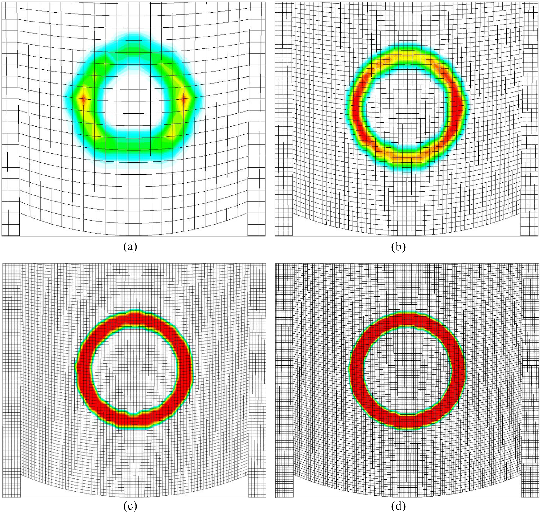
Comparison of mesh generation for the shape of a hollow droplet: (a) mesh element size 0.5 mm and total grid number 7500, (b) mesh element size 0.2 mm and total grid number 90,000, (c) mesh element size 0.13 mm and total grid number 320,000, and (d) mesh element size 0.1 mm and total grid number 660,000.
Validation
An experimental investigation was compared to the morphological outcome simulation of glycerin hollow droplet impact on a flat surface. The problem was simulated using the Volume Of Fluid (VOF) model and OpenFoam software. A glycerin hollow droplet with an initial diameter of D = 5.25 mm impacts a solid flat surface at

Comparison of experimental work 21 and simulation results for hollow droplet impact.
Results and discussions
Impact process
Figure 4 shows the hydrodynamic behavior of a hollow droplet on a solid concave obstacle. At an impact velocity of 5 m/s, a hollow droplet with an outer diameter of 5.25 mm and an inner diameter of 4 mm impacted on a concave surface with a length of 10 mm and a height of 1 mm. Figure 4 shows the morphology of the impact process at six different periods. The droplet collides with the surface and spreads across the concave surface, generating the jet fluid. Figure 4(b) shows how the jet fluid formed on the surface until it reached the concave surface’s end. At the same time, the air cavity contracted, the counter jet arose, and the upper shell thickness decreased. Jet fluid splashed in the air and traveled toward at 1 ms. Because of gravity, the front of the jet is moved lower. The jet-fluid is stretched and thinned at 2 ms, and counter jet contact with the hemispherical upper shell occurs. In Figure 4(e), the upper hemispherical shell ruptured due to contact with the counter jet. The jet fluid splashed and stretched due to the high kinetic energy, and the jet fluid broke after a few milliseconds.

Morphology of hollow droplet case 1 in impact process at different times after impact: (a) 0.1 ms, (b) 0.3 ms, (c) 1 ms, (d) 2 ms, (e) 3 ms, and (f) 4 ms.
Figure 5 is shown the pressure distribution in case 1, which shows two high gauge pressure zones. The top hemispherical shell and the lower hemispherical shell collide in these two areas. The bottom shell grew on the concave surface as the upper shell slid toward the surface. As the high-pressure zones neared the edge wall, the pressure was lowered.
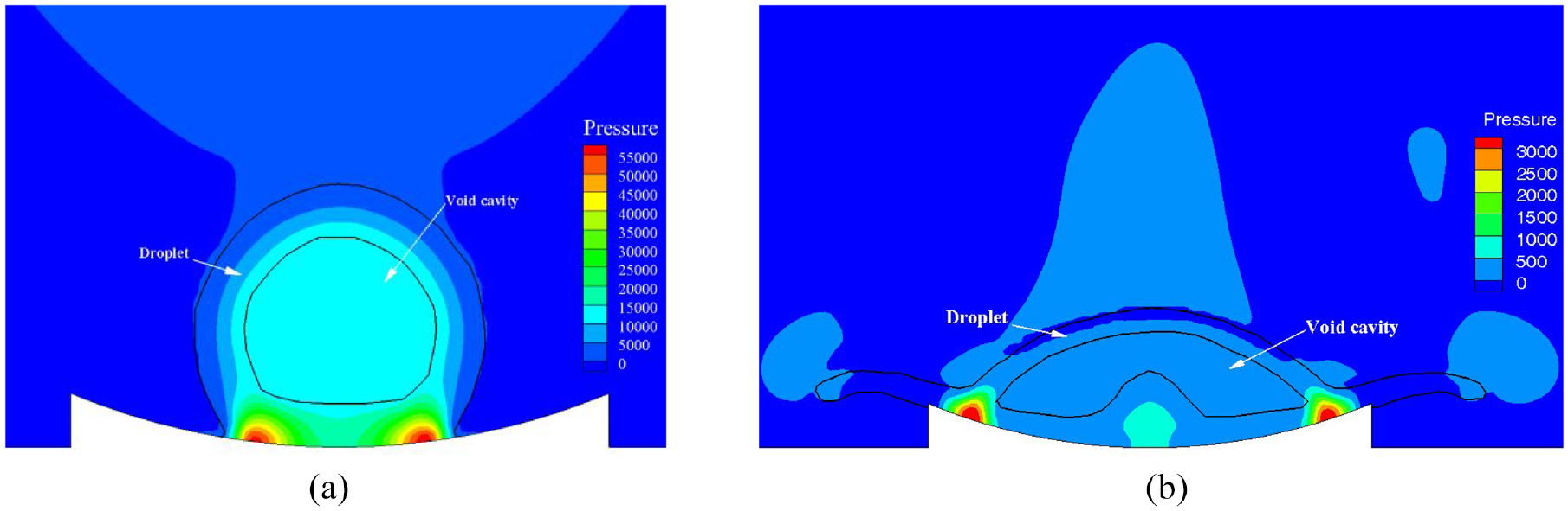
Pressure distribution case 1 in times after impact (a) 0 ms and (b) 1 ms.
Morphology of impacting hollow droplets
The shape of hollow droplet impact on a concave obstacle with a 1 mm edge wall height is depicted in Figure 6. Case 1, case 4, and case 7 each collided at a distinct impact velocity of 5, 10, and 15 m/s. At various times of 0.3, 2, and 4 ms, dynamic behavior was explored, and several points were noticed that we will analyze. In case 1, the jet fluid was produced on the concave surface and reached the end of the surface at 0.3 ms, but when the height of the wall increased, the jet had to travel a longer distance and couldn’t reach the end in case 7. With increasing edge wall height, the jet fluid may be more resistant to gravity. Cases 4 and 7 experienced the rupture phenomena at 2 ms. The rupture occurred sooner when the edge wall height was increased, and the reason for this was that the counter jet is rose quicker. Jet fluid spilled on the air expanded and thinned at 4 ms, producing jet fragmentation and, in case 7, disappearance.

Morphology of hollow droplet impact on the concave surface at the same impact velocity 5 m/s at different edge wall heights of the concave surface.
Figure 7 depicts the hydrodynamic behavior of a hollow droplet impacting on a concave mounted obstacle with varying edge wall heights at a 10 m/s impact velocity. In cases 2 and 5, the fluid jet spreads over the concave surface and splashes on the air at 0.3 ms. Because the space around a hollow droplet shrinks as the curvature increases, the top hemispherical shell deforms as the height of the outer wall rises. Case 2 had the rupture phenomena at 1 ms, while instances 5 and 8 had the rupture phenomenon before 1 ms. In all of the situations in Figure 7, the jet fluid splashed out of the concave surface. The jet fluid in case 2 separates at 2 ms, and it has happened several times in case 8. Case 5 has been extended, and a jet fluid separation is on the horizon. As the impact velocity rises from 5 to 10 m/s, the rupture time increases and the jet fluid develops.
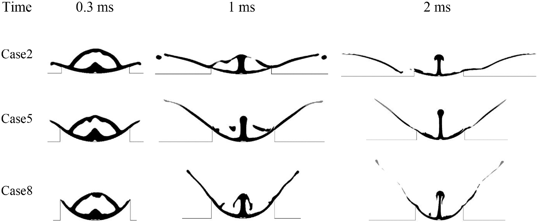
At different edge wall heights of the concave surface, the morphology of hollow droplet impact on the concave surface at the same impact velocity of 10 m/s.
Figure 8 shows the hydrodynamic behavior of a hollow droplet impacting on a concave obstacle with varying edge wall heights at a 15 m/s impact velocity. The hollow droplet collided with the concave surface after 0.3 ms. In cases 3, 6, and 9, the counter jet was elevated after impact. The rapid speed of the hit caused the counter jet to rise and the air cavity high pressure to burst the upper shell. In case 3, the counter jet collided with the upper hemispherical shell and burst it in 1 ms. In case 9, the counter jet comes into touch with shell and is linked to a component of the top shell, therefore don’t let the jet rise too rapidly and damage it under all cases. In case 3, the jet fluid splashed and separated about 2 ms toward the edge wall. In case 6, the jet fluid stretched and virtually split. The vertical direction of the force in the jet fluid cannot overcome gravity since it has a curved form with a 1 mm edge wall height.

At different edge wall heights of the concave surface, the morphology of hollow droplet impact on the concave surface at the same impact velocity of 15 m/s.
Effects of height edge wall on flow characteristics
Length of the counter jet diagrammed at same impact velocity in different height of edge wall in Figure 9. Counter jet length increased during the time in all cases. At impact velocity 5 m/s in Figure 9(a), jet length increased but during the time rate of rising decreased. Also, the gradient of counter jet length has changed in t = 2.2 ms for cases 1 and t = 1.6 ms for cases 4 and 7 because of the rupture phenomenon in the upper shell. In Figure 9(a), counter jet length increased with increasing the height of the edge wall. Counter jet length compared between case 2, case 5, and case 8 in the diagram illustrated in Figure 9(b). Results are shown case 2 has less amount of length than the other cases and case 5 has more amount length rather than case 8, unlike the Figure 9(a). At an impact velocity of 10 m/s counter jet contact sooner with the upper shell than the V = 5 m/s, so observed time of change in gradient of length happened before t = 1 ms. In Figure 9(b) length of counter jet for case 5 and 8 increased linearly with an increase of the impact velocity from 5 to 10 m/s, the maximum amount of length obtained during the t = 3 ms at 10 m/s is more than double from 5 m/s. Figure 9(c) is shown the length of the counter jet with different heights of the edge wall at an impact velocity of 15 m/s. Amount of length in cases 6 and 9 is less than case 3 in the initial time after impact, this reason for the rupture phenomenon occurred at the beginning. After t = 0.6 ms, the length of the counter jet increased linearly in cases 6 and 9, so have more amount about a case 3. Also results show the increasing impact velocity increased the length of the counter jet.

Length of the counter jet in different heights of the edge wall at impact velocity: (a) at impact velocity 5 m/s, b) at impact velocity 10 m/s, and (c) at impact velocity 15 m/s
In the schematic Figure 10, the height (

Schematic diagram of the height (
The jet fluid crossed the concave surface and splashed into the air as it reached the end of the concave surface. As a result, the length of the splashed jet fluid is estimated and shown in Figure 11. In all cases, the length of the jet increased with the passage of time, however there were minor differences in the length of the jet fluid in certain circumstances. At an impact velocity of 5 m/s, the jet fluid splashed length in different heights on the edge wall is depicted in Figure 11(a). The jet length rose until t = 1.6 ms, when a portion of jet fluid separated and the jet length varied, before continuing to rise. This happened in case 4, when the top of the jet fluid vanished into the air, causing the length to drop at t = 2.2 ms and then increase. In comparison to the other instance in Figure 11(a), case 7 grew slowly and had a shorter length of jet fluid splashed. Because the angle between the end of the concave surface and the horizon is shorter in case 1, the velocity horizontally is greater than the vertically in case 1, and inversely in case 3. At a 10 m/s impact velocity, the jet fluid splashed in case 2 loses a chunk of the jet at t = 0.6 ms, and the length is increased. Case 2 also has the most jet fluid length compared to cases 5 and 8. Because the jet fluid is separated at the commencement of the jet after t = 2 ms, and it is no longer the jet fluid, the length computed is less than in Figure 11(a). In case 5, the jet fluid vanishes and the slope of the chart lowers, causing the jet length to grow linearly in case 8. The length of jet fluid splattered in cases 3, 6, and 9 during the period following impact is shown in Figure 11(c). Because case 9 has a larger surface area on the concave, it is started later than the previous instances. At an impact velocity of 15 m/s, it seems that case 3 with h = 1 mm had the longest length while case 9 with h = 3 mm had the shortest length. The length of the jet rose when the impact velocity was raised from 5 to 10 m/s, but it did not change when the velocity was increased from 10 to 15 m/s because the high-velocity impact created a lot of force and speed in the jet and evaporated the jet fluid in the air.

Length of jet fluid splashed in various heights of edge wall at impact velocity: (a) at impact velocity 5 m/s, (b) at impact velocity 10 m/s, and (c) at impact velocity 15 m/s.
At the same impact velocity, the height of the jet fluid splashed on the air in varied edge wall heights is shown in Figure 12. Case 1 started at t = 0.2 ms and grew until t = 3 ms, resulting in a maximum amount height of 1.5 mm at a 5 m/s impact velocity. In case 4, with an edge wall height of h = 2 mm, the jet fluid is computed at t = 0.2 ms and increased until t = 2 ms (h = 3 mm), when the portion of the jet fluid separated and the height reduced to h = 2.38 mm, before rising to 3.19 mm. The height jet fluid is determined at t = 0.6 ms and raised to the maximum quantity of h = 1.98 mm at t = 3 ms in case 7. At a 10 m/s impact velocity, the height of the jet fluid spilled increased over time, reaching its maximum level at t = 2 ms. The least amount in this velocity was 3.65 mm in case 2, the highest was 8.54 mm in case 5, and the minimum was 9.57 mm in case 8. In case 5, the jet fluid separated in t = 1 ms. At a 15 m/s impact velocity, the jet height grew over time, but the higher the velocity, the more the jet fluid splattered on the air was evaporated. The height of the jet grew when the impact velocity was raised from 5 to 10 m/s, but when the velocity was increased from 10 to 15 m/s, the length did not change or decrease because the high-velocity impact created a lot of force and speed in the jet and evaporated the jet fluid in the air.
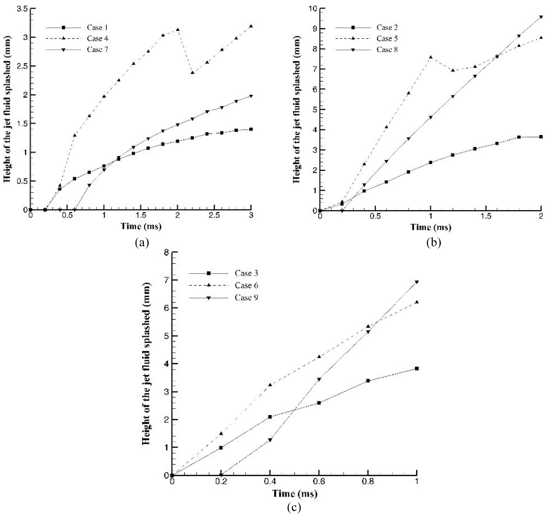
Height of jet fluid splashed in different heights of edge wall at impact velocity: (a) at impact velocity 5 m/s, (b) at impact velocity 10 m/s, and (c) at impact velocity 15 m/s.
Conclusion
The impact of a hollow droplet on a solid concave mounted obstacle is studied in this research at various heights of the edge wall and impact velocity. In this work, the dynamic behavior and jet characteristics were studied. The findings are obtained using the Volume Of Fluid (VOF) technique in OpenFoam software. The modeling of hollow droplet impact was examined, and the following are some key points:
In all cases, the collision of a hollow droplet on a concave solid obstacle resulted in the production of a counter jet. The length of the counter jet is determined by the impact velocity and the size of the edge wall.
With increased impact velocity and wall edge height, the height of the counter jet rose. In case 6, the counter jet reached a maximum length of 13.9 mm, while the minimum length of 2.81 mm occurred in case 1. When the impact velocity rose from 5 to 10 m/s, the length of the counter jet grew 135%, and when the impact velocity climbed from 5 to 15 m/s, the length of the jet increased 215%.
When the height of the edge wall was reduced, the length of the jet fluid splattered on the air increased. When the impact velocity was increased from 5 to 10 m/s, the length of the jet increased, but it did not alter when the velocity was increased from 10 to 15 m/s. The largest amount of length that occurred in case 3 is 19.74 mm, while the least amount of length that occurred in case 7 is 2.73 mm.
As the height of the edge wall became taller, the height of the jet fluid splattered on the air grew taller. When the impact velocity was increased from 5 to 10 m/s, the height of the jet increased, but when it was increased from 10 to 15 m/s, the height of the jet decreased. Case 8 had the most quantity of jet fluid splashed height at 9.75 mm, while case 1 had the lowest at 1.4 mm.
Footnotes
Appendix
Handling Editor: Chenhui Liang
Declaration of conflicting interests
The author(s) declared no potential conflicts of interest with respect to the research, authorship, and/or publication of this article.
Funding
The author(s) received no financial support for the research, authorship, and/or publication of this article.